
Related Manuals for CAME G6000


Summary of Contents for CAME G6000
- Page 1 Automatic road barriers FA01625-EN G6000 G6001 G6001-316 G6000X G6000Y G6010 G6010X English INSTALLATION MANUAL...
-
Page 2: Manual Release
MANUAL RELEASE Releasing the device may be dangerous for the user, if the boom fastening has been damaged or if the boom is no longer intact, as the result of an accident or installation error. In these cases, the tensioned springs no longer guarantee that the boom is balanced. The boom may suddenly rotate when being released. Manual release may cause the operator to move in an uncontrolled manner due to a mechanical fault or an imbalance. - Page 3 • The manufacture date is provided in the production batch printed on the product label. If necessary, contact us at https://www.came.com/global/en/contact-us. • The general conditions of sale are given in the official CAME price lists.
-
Page 4: Dismantling And Disposal
DISMANTLING AND DISPOSAL CAME S.p.A. employs an Environmental Management System at its premises. This system is certified and compliant with the UNI EN ISO 14001 standard to ensure that the environment is respected and safeguarded. Please continue safeguarding the environment. At CAME we consider it one of the fundamentals of our operating and market strategies. - Page 5 (**) The average product life specified should be understood purely as an indicative estimate. It applies to normal usage conditions and where the product has been installed and maintained in compliance with the instructions provided in the CAME technical manual. The average product life is also affected, including significantly, by other variables such as, but not limited to, climatic and environmental conditions.
-
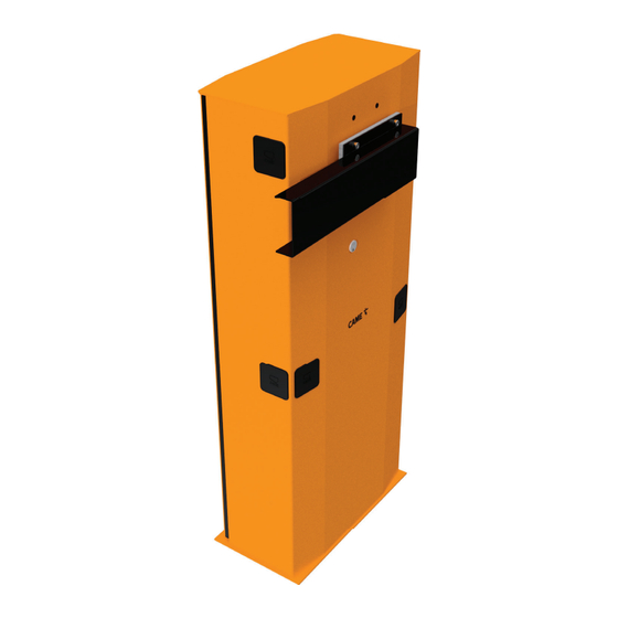
Page 6: Description Of Parts
Description of parts Barrier Boom attachment Mechanical stops Boom anchoring plate Balance springs Lock for release Control panel Cabinet Anchoring plate Inspection hatch Anchoring brackets Microswitch support plate... - Page 7 Control board ZL39B Terminal board for connecting control and safety devices Terminal board for limit-switch micro-switches Terminal board associated with the RSE connector for paired, alternate or CRP Terminal board for connecting the antenna connection Connector for plug-in radio frequency card (AF) Terminal board for connecting the keypad selector RSE card connector Terminal board for connecting the transponder selector switch...
- Page 8 Cable types and minimum thicknesses Cable length (m) up to 20 from 20 to 30 Power supply 230 V AC 3G x 1.5 mm² 3G x 2.5 mm² Power supply 120 V AC 3G x 1.5 mm² 3G x 2.5 mm² 24 V AC/DC flashing beacon 2 x 1 mm²...
-
Page 9: Installation
INSTALLATION The following illustrations are examples only. The space available for fitting the operator and accessories varies depending on the area where it is installed. It is up to the installer to find the most suitable solution. In case of manual handling, have one person for every 20 kg that needs hoisting; for non-manual handling, use proper hoisting equipment in safe conditions. When the operator is being fixed in place, it may be unstable and overturn. - Page 10 Fill the hole with soil around the concrete block. Remove the nuts from the screws. Insert the electrical cables into the tubes until they protrude by about 600 mm. Preparing the barrier Fastening the barrier...
- Page 11 Changing the boom opening direction The barrier is set up for installation on the left. If the boom has already been assembled, lift it up to a vertical position and remove it. Release the gearmotor using the key to run the procedure for changing the boom opening direction.
- Page 12 Remove the cover on the micro limit switches and remove the microswitch activation block. Unscrew the boom anchoring plate. Unscrew the upper mechanical stop and hex screw. Remove the lower mechanical stop, unscrewing the relevant screws. Loosen both balance springs and unhook them from the anchoring bracket. Release the transmission lever from the lever arm, unscrewing the screw.
-
Page 13: Boom Installation
Boom installation Insert the boom between the boom attachment and the boom anchoring plate and fasten using screws. First install the LED strip (where applicable), ONLY THEN fix the flange and the intermediate plate. Choosing the hole for fixing the balance spring The barrier is supplied as standard with springs (Ø... - Page 14 Balancing the boom Position the boom vertically. Release the gearmotor. Lock the gearmotor Loosen the clamping nut on the rod. Manually turn the spring to increase or reduce the traction. The boom should Check the proper working state of the spring. When the boom is vertical, the stabilise at 45°.
- Page 15 Determining the travel end points with mechanical limit switches Check that the boom is parallel to the road surface when it is in the closed position and at about 89° when it is in the open position. Correct the boom’s horizontal position Release the gearmotor.
- Page 16 Correct the boom’s vertical position Release the gearmotor. Open the inspection hatch. Turn the transmission lever until the boom is in the desired position. Tighten the nuts to block the transmission lever. Lock the gearmotor ~1° ~89°...
-
Page 17: Electrical Connections
ELECTRICAL CONNECTIONS Passing the electrical cables The electrical cables must not touch any parts that may overheat during use (such as the motor and transformer). Make sure that the moving mechanical parts are suitably far away from the wiring. Power supply Make sure the mains power supply is disconnected during all installation procedures. - Page 18 Maximum capacity of contacts The total power of the outputs listed below must not exceed the maximum output power [Accessories] Device Output Power supply (V) Power (W) Accessories 10 - 11 24 AC Additional light 10 - E1 24 AC Flashing beacon 10 - E1 24 AC...
-
Page 19: Signalling Devices
Signalling devices Additional light It increases the light in the manoeuvring area. Additional flashing beacon It flashes when the operator opens and closes. Operator status warning light It notifies the user of the operator status. Rope light It flashes when the operator opens and closes. 10 11 E1 E6 Rx Tx 3P 4 Safety devices... - Page 20 Connection with Sleep Mode Multiple photocell pairs can be connected. 10 11 E1 E6 Rx Tx 3P 4 See function F60, Sleep Mode. 11 NO C NC DIR / DELTA-S photocells Standard connection Connection with safety test Multiple photocell pairs can be connected. Multiple photocell pairs can be connected.
- Page 21 DXR/DLX photocells DXR/DLX photocells Standard connection Connection with safety test Multiple photocell pairs can be connected. Multiple photocell pairs can be connected. See function [F5] Safety devices test. 10 11 E1 E6 Rx Tx 3P 4 10 11 E1 E6 Rx Tx 3P 4 10 11 OUT 10 11 SY...
-
Page 22: Getting Started
PROGRAMMING Programming button functions ESC button The ESC button is used to perform the operations described below. Exit the menu Delete the changes Go back to the previous screen < > buttons The <> buttons are used to perform the operations described below. Navigate the menu Increase or decrease values ENTER button... - Page 23 Safety devices test Check that the photocells connected to the inputs are operating correctly, after each opening and closing command. Safety devices test 0 =Deactivated (Default) 1 = CX 2 = CY 3 = CX+CY Hold-to-run With the function active, the operator stops moving (opening or closing) when the control device is released. When the function is active, it excludes all other control devices.
- Page 24 Automatic closure Set the time before automatic closure is activated, once the opening travel end point has been reached. The function does not work if any of the safety devices are triggered when an obstacle is detected, after a complete stop, during a power outage or if there is an error.
- Page 25 Configure the function to be performed by the card inserted in the RSE1 connector. 0 =Deactivated (Default) 1 = Paired 2 = Compass 3 = CRP/CAME KEY Save data Save user data, timings and configurations to the memory device (memory roll or USB key). Save data...
- Page 26 RSE speed Set the remote connection system communication speed on the RSE port. 0 = 1200 bps 1 = 2400 bps 2 = 4800 bps 3 = 9600 bps 4 = 14400 bps 5 = 19200 bps 6 = 38400 bps (default) 7 = 57600 bps 8 = 115200 bps New user...
-
Page 27: Import/Export Data
Parameter reset Restore factory settings except for the functions: [Radio decoding], [Boom length] and the settings related to travel calibration. Parameter reset 0 =Deactivated (Default) 1 = Activated Manoeuvre counter View the number of manoeuvres performed by the operator (1 = 1000 manoeuvres). Manoeuvre counter 1 = 1000 maneuvers FW version... -
Page 28: Final Operations
FINAL OPERATIONS PAIRED OPERATION Two connected operators are controlled with one command. Electrical connections Connect the two electronic boards with a UTP CAT 5 cable. Fit an RSE card on both control boards using the RSE connector. Connect up the electrics for the devices and accessories. For information on connecting the electrics for the devices and accessories, please see the “ELECTRICAL CONNECTIONS”... -
Page 29: Operating Modes
Saving users All save user operations must be performed only on the control board set as the MASTER. For user storage operations, see function U1. Operating modes STEP-BY-STEP or OPEN ONLY command PARTIAL OPENING command (2-3P) MASTER MASTER SLAVE SLAVE ALTERNATE OPERATION The first barrier opens, the vehicle passes, the first barrier closes, the second barrier opens, the vehicle passes and the second barrier closes. - Page 30 Programming All programming operations described below must be performed only on the control board set as the MASTER. Select function F49. Press ENTER to confirm. Select 2. Select function F52. Select 1. Saving users All save user operations must be performed only on the control board set as the MASTER. For user storage operations, see function U1.
-
Page 31: Error Messages
STEP-BY-STEP command (2-7) on barrier A or B for emergency opening ERROR MESSAGES Service test failure error Maximum number of detected obstructions Transformer overheating Release mechanism activated Open contact on thermal terminal Both limit switches are open Incompatible transmitter error MCBF Before carrying out any cleaning or maintenance, or replacing any parts, disconnect the device from the power supply. - Page 32 CAME S.p.A. Via Martiri della Libertà, 15 31030 Dosson di Casier Treviso – Italy Tel. (+39) 0422 4940 Fax (+39) 0422 4941...
Need help?
Do you have a question about the G6000 and is the answer not in the manual?
Questions and answers