Table of Contents
Advertisement
Quick Links
Download this manual
See also:
Instruction Manual
SERVICE MANUAL
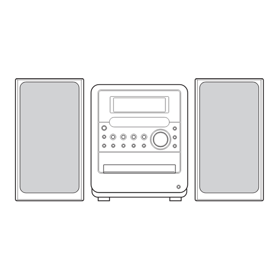
MICRO COMPONENT SYSTEM
12
2004
MB338
1
PRECAUTION. . . . . . . . . . . . . . . . . . . . . . . . . . . . . . . . . . . . . . . . . . . . . . . . . . . . . . . . . . . . . . . . . . . . . . . . . 1-3
2
SPECIFIC SERVICE INSTRUCTIONS . . . . . . . . . . . . . . . . . . . . . . . . . . . . . . . . . . . . . . . . . . . . . . . . . . . . . . 1-6
3
DISASSEMBLY . . . . . . . . . . . . . . . . . . . . . . . . . . . . . . . . . . . . . . . . . . . . . . . . . . . . . . . . . . . . . . . . . . . . . . . 1-7
4
ADJUSTMENT . . . . . . . . . . . . . . . . . . . . . . . . . . . . . . . . . . . . . . . . . . . . . . . . . . . . . . . . . . . . . . . . . . . . . . . 1-28
5
TROUBLESHOOTING . . . . . . . . . . . . . . . . . . . . . . . . . . . . . . . . . . . . . . . . . . . . . . . . . . . . . . . . . . . . . . . . . 1-32
UX-QD9S
(SP-UXQD9S)
(CA-UXQD9S)
TABLE OF CONTENTS
COPYRIGHT © 2004 Victor Company of Japan, Limited
Area suffix
A ------------------------ Australia
US ------------------------ Singapore
UN ----------------------------- Asean
(SP-UXQD9S)
No.MB338
2004/12
Advertisement
Chapters
Table of Contents

Related Manuals for JVC UX-QD9S


Summary of Contents for JVC UX-QD9S
-
Page 1: Table Of Contents
SERVICE MANUAL MICRO COMPONENT SYSTEM MB338 2004 UX-QD9S Area suffix A ------------------------ Australia US ------------------------ Singapore UN ----------------------------- Asean (SP-UXQD9S) (CA-UXQD9S) (SP-UXQD9S) TABLE OF CONTENTS PRECAUTION............... . . 1-3 SPECIFIC SERVICE INSTRUCTIONS . - Page 2 85 dB/W·m 140 mm (W) × 231 mm (H) × 204.5 mm (D) Dimensions Mass (approx.) 2.2 kg (1 unit) Micro component system (UX-QD9S) 445 mm (W) × 231 mm (H) × 355 mm (D) General Dimensions Mass (approx.) 9.0 kg •...
-
Page 3: Precaution
SECTION 1 PRECAUTION Safety Precautions (1) This design of this product contains special hardware and voltmeter. many circuits and components specially for safety purpos- Move the resistor connection to each exposed metal es. For continued protection, no changes should be made part, particularly any exposed metal part having a return to the original design unless authorized in writing by the path to the chassis, and measure the AC voltage across... - Page 4 Preventing static electricity Electrostatic discharge (ESD), which occurs when static electricity stored in the body, fabric, etc. is discharged, can destroy the laser diode in the traverse unit (optical pickup). Take care to prevent this when performing repairs. 1.5.1 Grounding to prevent damage by static electricity Static electricity in the work area can destroy the optical pickup (laser diode) in devices such as laser products.
-
Page 5: Important For Laser Products
Important for laser products 5.CAUTION : If safety switches malfunction, the laser is able 1.CLASS 1 LASER PRODUCT to function. 2.DANGER : Invisible laser radiation when open and inter 6.CAUTION : Use of controls, adjustments or performance of lock failed or defeated. Avoid direct exposure to beam. procedures other than those specified here in may result in 3.CAUTION : There are no serviceable parts inside the hazardous radiation exposure. -
Page 6: Specific Service Instructions
SECTION 2 SPECIFIC SERVICE INSTRUCTIONS This service manual does not describe SPECIFIC SERVICE INSTRUCTIONS. 1-6 (No.MB338) -
Page 7: Disassembly
SECTION 3 DISASSEMBLY Main body section 3.1.1 Removing the rear cover (See Figs.1 and 2) (1) From the back side of the main body, remove the eleven screws A attaching the rear cover. (See Fig.1.) (2) From the bottom side of the main body, remove the three screws B attaching the rear cover. - Page 8 3.1.2 Removing the side panels (L)/(R) (See Fig.3) • Remove the rear cover. (1) From the bottom side of the main body, remove the two Side panel(R) screws C attaching the side panels (L)/(R). (2) Slide the side panels (L)/(R) in the direction of the arrow and remove the side panels (L)/(R).
- Page 9 3.1.4 Removing the front panel assembly (See Figs.6 to 8) • Remove the rear cover, side panels(L)/(R) and top cover as- sembly. Front panel assembly (1) From the left side of the main body, disconnect the card wires from the connectors (CN702, CN710) on the micon board.
-
Page 10: No.mb338)1
3.1.5 Removing the fan motor (See Figs.9 and 10) • Remove the rear cover, side panels(L)/(R) and top cover as- sembly. Tuner bracket (1) From the back side of the top cover assembly, remove the Fan motor screw G attaching the fan motor. (See Fig.9.) Reference: When attaching the screw G, attach the spacer with it. - Page 11 3.1.8 Removing the heat sink (See Fig.11) • Remove the rear cover, side panels(L)/(R) and top cover as- sembly. Heat sink (1) From the back side of the main body, remove the eight screws N attaching the heat sink. (2) Remove the heat sink from the main board and regulator board.
-
Page 12: No.mb338)1
3.1.10 Removing the regulator board (See Fig.14) • Remove the rear cover, side panels(L)/(R), top cover assem- bly, heat sink and main board. Regulator board (1) From the top side of the main body, disconnect the wire Transformer CN202 from the connector CN902 on the transformer board. - Page 13 3.1.12 Removing the power transformer (See Fig.16) • Remove the rear cover, side panels(L)/(R), top cover assem- bly, heat sink, main board, regulator board and transformer board. (1) From the reverse side of the transformer board, remove the solders from the sections f on the transformer board. (2) Remove the power transformer from the transformer board.
- Page 14 3.1.14 Removing the joint board (See Fig.18) • Remove the rear cover, side panels(L)/(R), top cover assem- bly, heat sink, main board, regulator board and transformer CN805 board. Micon board Reference: Remove the jack board as required. (1) From the back side of the main body, remove the two screws X attaching the joint board.
- Page 15 3.1.16 Removing the DVD mechanism assembly (See Figs.21 and 22) • Remove the rear cover, side panels(L)/(R), top cover assem- bly, heat sink, main board, regulator board, transformer board CN711 CN705 and joint board. (1) From the top side of the main body, disconnect the card Card Card wires from the connectors...
- Page 16 3.1.17 Removing the headphone board (See Fig.23) • Remove the rear cover, side panels(L)/(R), top cover assem- bly, heat sink, main board, regulator board, transformer board, Headphone board joint board and DVD mechanism assembly. Spacer (1) From the right side of the main body, remove the screw AC attaching the headphone board.
- Page 17 DVD mechanism assembly section • Remove the DVD mechanism assembly from the main body. (See "3.1.16 Removing the DVD mechanism assembly".) 3.2.1 Removing the DVD cover (See Fig.1) (1) From the top side of the DVD mechanism assembly, re- Double-stick tape move the two screws A attaching the DVD cover.
- Page 18 3.2.3 Removing the tray assembly (See Figs.3 and 4) • Remove the DVD cover. Tray assembly DVD mechanism assembly (1) From the right side of the DVD mechanism assembly, push the slide cam and pull the tray assembly out of the DVD mechanism assembly in the direction of the arrow.
- Page 19 3.2.5 Removing the traverse mechanism assembly (See Figs.6) • Remove the DVD cover. DVD mechanism assembly (1) From the bottom side of the DVD mechanism assembly, re- move the four screws D attaching the traverse mechanism DVD module board assembly. (2) Take out the traverse mechanism assembly with the DVD module board.
-
Page 20: See Figs.7, 9 To
3.2.7 Removing the pickup (See Figs.7, 9 to 11) • Remove the DVD cover and traverse mechanism assembly. (1) From the side of the traverse mechanism assembly, solder Plate Thrust spring the short land sections e of the pickup. (See Fig.7.) (2) Release the lock of the connector of the pickup in the direc- tion of the arrow and disconnect the card wire. - Page 21 3.2.8 Attaching the pickup (See Figs.7, 9 to 12) • See "3.2.7 Removing the pickup". Feed gear M (1) Attach the shaft, SW actuator and LEAD spring to the pick- up. (See Fig.11.) (2) Align the pickup to the section m of the traverse mecha- nism assembly first, and set the both ends of the shaft of the pickup in the sections (j, k) of the traverse mechanism assembly.
-
Page 22: No.mb338)1
3.2.9 Removing the feed motor (See Figs.13 to 15) • Remove the DVD cover and traverse mechanism assembly. Thrust spring (1) From the top side of the traverse mechanism assembly, re- Traverse mechanism assembly move the screw H attaching the plate and thrust spring. (See Fig.13.) Plate (2) Remove the plate from the joint n of the feed holder and... - Page 23 3.2.11 Removing the DVD loading switch board (See Fig.17) (1) From the bottom side of the DVD mechanism assembly, re- DVD loading switch board move the screw M attaching the DVD loading switch board. Wires Motor (2) Remove the wires from the soldered sections r on the DVD loading switch board.
- Page 24 Cassette mechanism assembly 3.3.1 Removing the Play/Record & Clear head Cassette mechanism assembly Fly wheelR (See Fig.1~3) (1) While moving the trigger arm on the right side of the head mount in the direction of the arrow, turn the flywheel R counterclockwise until the head mount comes ahead and clicks.
- Page 25 3.3.2 Removing the head amplifier & mechanism control board (See Fig.4) (1) Turn over the cassette mechanism assembly and remove Main motor assembly the three screws A attaching the head amplifier & mecha- nism control board. Capstan belt (2) Disconnect the flexible wire from connector CN31 on the head amplifier &...
- Page 26 3.3.4 Removing the flywheel (See Fig.8, 9) • Prior to performing the following procedure, remove the head amplifier & mechanism control board and the main motor as- sembly. (1) From the front side of the cassette mechanism, remove the slit washers attaching the capstan shaft L and R. Pull out the flywheels backward.
- Page 27 3.3.6 Reattaching the Play/ Record & Clear head (See Fig.11~13) (1) Reattaching the head mount assembly. a) Change front of the direction cover of the head mount assembly to the left (Turn the head forward). b) Fit the bosses O', P', Q', U' and V' on the head mount assembly to the holes P and V, the slots O, U and Q of the mechanism sub assembly (See Fig.11 to 13).
-
Page 28: Adjustment
SECTION 4 ADJUSTMENT Adjustment method for DVD section 4.1.2 Adjustment and check items (1) EEPROM initialization 4.1.1 Jigs and test instruments (2) Upgrade of back-end firm (1) Upgrade disc (3) Upgrade of system microcomputer (ROM correction) (2) Remote controller (4) Confirm of region code and system control version (5) DVD IOP check 4.1.3 Adjustment and check method 1. - Page 29 2. Upgrade of back-end firm 3. Upgrade of system microcomputer (ROM correction) This set can do upgrade of a back-end firm with an upgrade disc. This set can do upgrade of a microcomputer with a ROM correction disc. LCD indication Source : DVD NO DISC LCD indication...
- Page 30 4. Confirmation of region code and system control version (1) Insert the AC power cord in an outlet while pressing both the [STOP] key and [DVD PLAY] key on the main unit and put the main unit in a test mode. (2) Indication of LCD changes sequentially as follows by pushing a [MENU] key of a remote controller.
- Page 31 5. DVD IOP check Confirm that a disc is not in a tray. (1) Insert the AC power cord in an outlet while pressing both the [STOP] key and [DVD PLAY] key on the main unit and put the main unit in a test mode. (2) Turn indication of LCD into CHECK by pushing a [MENU] key of a remote controller.
-
Page 32: Troubleshooting
SECTION 5 TROUBLESHOOTING This service manual does not describe TROUBLESHOOTING. 1-32 (No.MB338) - Page 33 (No.MB338)1-33...
- Page 34 Victor Company of Japan, Limited AV & MULTIMEDIA COMPANY AUDIO/VIDEO SYSTEMS CATEGORY 10-1,1chome,Ohwatari-machi,Maebashi-city,371-8543,Japan (No.MB338) Printed in Japan...
- Page 35 SCHEMATIC DIAGRAMS MICRO COMPONENT SYSTEM UX-QD9S CD-ROM No.SML200412 Area suffix A ------------------------ Australia US ------------------------ Singapore UN ----------------------------- Asean (SP-UXQD9S) (CA-UXQD9S) (SP-UXQD9S) Contents Block diagram Standard schematic diagrams 2-10 to 13 Printed circuit boards No.MB338SCH COPYRIGHT 2004 Victor Company of Japan, Limited.
- Page 36 In regard with component parts appearing on the silk-screen printed side (parts side) of the PWB diagrams, the parts that are printed over with black such as the resistor ( ), diode ( ) and ICP ( ) or identified by the " " mark nearby are critical for safety.
-
Page 37: Block Diagram
Block diagram Jack section Main section Cassette mechanism section HEAD SWITCH L+, L– PBL,PBR IC32 COMPONENT R+, R– RECL,RECR PB/REC MECHA VIDEO OUT COMPLINK HEAD S6301 CYOUT PAL / NTSC IC33 CBOUT SWITCH SERIAL TO PARALLEL CROUT SW1,SW2 COMPO PORT EXTENSION SW5,SW6 YOUT FREC... - Page 38 Standard schematic diagrams Transformer section LVA10524-A2 LVA10524-A3 CN201 QGB2510K2-09 T9001 S1GND B9601 19.3V 9.2V R2402 FANUP CN902 B9902 QGA2501F1-05 FT922 FT921 S2GND WR201 REGGND UX-QD7 MD5.4V 5.2V B9903 UX-QD9 R2401 DVD5V 9.2V 3.8V POUTMD 0.1V Q2401 9.5V B9904 FT932 FT931 2SD601A/RS/-X QNG0003-001Z QNG0003-001Z...
- Page 39 Main section LVA10523-A1 2SD601A/RS/-X Q3101 R3111 IC101 R3193 AUXL LA4628 0.1V AUX-L MTZJ4.7C-T2 R3102 C3192 9.1K AUX-R R3304 C3292 R3293 AUXR C3117 R3108 R3309 1.8K 1/4W 0.082 SILMIC R3101 C3118 C1109 10/35 R1111 9.3V 220K R3302 9.3V SILMIC 10/35 9.3V 2.2k 9.3V WR116...
- Page 40 System control section (SHEET 8) (SHEET 1) (SHEET 7) SLC-S302 CN33 TO LVA10524-A3 TO DVD MECHA QAU0348-001 (Dom)/QAU0346-001(Others) TO TAPE CN903 FTU-JZ1-11 TO TUNER CN1 CN711 WR701 CN703 QGF1036F1-05 CN709 QGF1205C1-09 QGF1205C1-11 SIGL IC751 LB1641 C7504 AGND SIGR C7355 RF10V 9.3V C7356 LEDGND...
- Page 41 SHEET 4...
- Page 42 DVD servo control section (1/2) D3.3V IC302 D3.3V LM1117MP-ADJ-X P3.3V P3.3V D1.2V C373 C374 K304 C372 C375 C376 R310 NQR0502-001X 0.47 C306 C359 K305 0.1/16 0.1/16 DGND MDQ9 EXDAT8 MDQ5 MDQ10 TP325 MDQ4 DGND TP324 TP323 MDQ11 TP322 MDQ3 TP321 TP320 R307 S3.3V...
- Page 43 DVD servo control section (2/2) R716 PCMCLK R719 C715 C713 IC704 IC705 R717 R720 P3.3V S3.3V D3.3V C712 C714 R701 R702 K501 NQR0129-002X IC505 K4S641632H-UC75 C553 22/6.3 C704 220/6.3 DGND C502 TP54 C551 0.1/16 IC701 AK4384VT-X MDQ0 MDQ15 K710 NQR0129-002X IC501 C558 C503...
- Page 44 LED & DVD loading section UDZS7.5B-X UDZS7.5B-X NSTM515AS QGF1006F2-07W QGF1006F1-07W QGF1037F2-07W TO CN705 (SHEET 3) UDZS7.5B-X UDZS7.5B-X NSTM515AS QSW1074-001 TO CN711 (SHEET 3) QGF1016F3-05 SHEET 7...
- Page 45 R108 RECL R106 R302 R110 2.2K C214 150P CN42 Q342 QGF1205F1-09 KRA111M-T C104 VR37 C102 QVP0077-103Z 0.01 220p R306 Q343 2SC3576-JVC-T 4.7K R336 R344 Q344 C340 2SC3576-JVC-T 47/50V CN32 4.7K QGF1205F1-09 R339 C341 Q345 R345 100K C304 1/50V 2SC3576-JVC-T 10/16V R304 4.7K...
-
Page 46: Printed Circuit Boards
Printed circuit boards Main board (Headphone board) (FL board) (Main board) C5611 R6094 R2806 WR101 CN110 R5016 R5015 C6071 IC601 K6001 R6070 R6079 R6071 R6076 C6072 L5603 C6002 C6008 R6012 C1111 R5602 R1105 C6073 R5601 R5603 R5604 C1211 R6072 R6073 WC561 R2804 WR115... - Page 47 (Transformer board) Micon board (Micon board) D9002 R9901 CN706 C9003 Q7301 R7301 R7302 TP701 Q7302 CN707 Q7903 Q7902 R7904 R7902 Q9001 D7902 R7303 CN701 R7601 R7304 Q7601 Q7901 Q7503 R7901 R7186 R7905 R7305 D7601 B7902 K7451 D7301 R7314 R7311 R7018 R7312 R7019 C7451...
- Page 48 DVD module board DVD loading switch board Forward side C508 C510 R558 K567 K565 C509 K566 C559 C558 K564 K501 C511 TP71 C555 C552 TP53 TP64 K555 TP77 TP52 TP63 TP73 R724 R502 TP55 R748 TP51 K721 IC703 R720 R712 R340 C547 R719...
- Page 49 Cassette switch board VR37 R371 FW100 Head amplifier board CN33 C374 PP300 R310 CN34 R105 R313 CN32 R342 C105 C107 C205 Q302 Q375 R372 C310 Q376 R205 Q372 R338 C314 C371 C313 R376 R375 R337 R335 L301 R305 C331 R353 C300 C304 R327...
- Page 50 Victor Company of Japan, Limited AV & MULTIMEDIA COMPANY AUDIO/VIDEO SYSTEMS CATEGORY 10-1,1chome,Ohwatari-machi,Maebashi-city,371-8543,Japan Printed in Japan (No.MB338SCH)
-
Page 51: Parts List
PARTS LIST [ UX-QD9S ] * All printed circuit boards and its assemblies are not available as service parts. Area suffix A ------------------------- Australia US ---------------------- Singapore UN ----------------------------Asean - Contents - 3- 2 Exploded view of general assembly and parts list (Block No.M1) 3- 6 Speaker assembly and parts list (Block No.M2) - Page 52 Exploded view of general assembly and parts list Block No. 13 12 FL board Key board Head...
- Page 53 Joint board Micon board 106 106 66 62 Trans board Regulator board Component board Jack board Main board Headphone board...
- Page 54 General Assembly Block No. [M][1][M][M] Symbol No. Part No. Part Name Description Local LV10934-019A FRONT PANEL LV40301-002A FELT SPACER (x2) LV21750-013A FRONT LENS LV21751-010A CD LENS LV35099-001A ORNAMENT QYSDSF2608ZA TAP SCREW M2.6 x 8mm(x2) GV30527-001A VOLUME ORNAMENT LV21752-002A MAIN BUTTON QYSDSF2608ZA TAP SCREW M2.6 x 8mm(x6)
- Page 55 Symbol No. Part No. Part Name Description Local QYSBSG3008ZA TAP SCREW M3 x 8mm VYSH101-009 SPACER (x2) LV30225-079A SPACER LV34035-001A SHIELD LV30225-0J1A SPACER LV30225-0M5A SPACER QYSBSF3010ZA TAP SCREW M3 x 10mm(x4) E65923-009 TAPPING SCREW GV40034-001A DAMPER ASSY. GV40220-001A LACH LV43579-001A DOOR SPRING QAU0346-001...
-
Page 56: Speaker Assembly And Parts List (Block No.m2)
Speaker assembly and parts list Block No. The parts without symbol number are not service. Speaker Block No. [M][2][M][M] Symbol No. Part No. Part Name Description Local LV21811-001A NET ASSY (x2) 5600008011 HOLDER (x8) 9000007941 FOOT (x8) LV43473-002A JVC MARK (x2) -
Page 57: Dvd Mechanism Assembly And Parts List (Block No.mj)
DVD mechanism assembly and parts list Block No. Grease FTU-JZ1-11M =JVG-31N =CFD-4007ZY2 =PG-641 =1401C < Back side > < Back side > 63.3mm 0.1mm DVD module board 10.5mm 0.1mm The parts without symbol number are not service. - Page 58 DVD mechanism Block No. [M][J][M][M] Symbol No. Part No. Part Name Description Local LV21814-001A MECHA BASE LE20731-001A SPINDLE BASE QYSDST2605M TAP SCREW M2.6 x 5mm(x2) LE40931-001A SHAFT LE40995-001A BAR SPRING QYSPSTU2080M TAP SCREW M2 x 8mm LE20730-002A FEED HOLDER QAR0165-001 FEED MOTOR LV41510-201A...
-
Page 59: Dvd Loading Base Assembly And Parts List (Block No.mn)
DVD loading base assembly and parts list Block No. FMU-JZ1-11M Grease JVG-31N FL-7750E Joint board LED board Backside Switch board The parts without symbol number are not service. - Page 60 DVD loading base Block No. [M][N][M][M] Symbol No. Part No. Part Name Description Local LV10932-003A LOADING BASE LV35052-001A PULLEY GEAR LV35053-001A MIDDLE GEAR LV35054-001A IDLE GEAR E407140-001SS C.D ROLLER E407149-001SS RUBBER TUBE LV35055-003A SLIDE CAM ASSY LV21749-002A ELEVATOR LV10933-003A TRAY NSTM515AS NSTM515AS...
-
Page 61: Cassette Mechanism Assembly And Parts List (Block No.mp)
Cassette mechanism assembly and parts list Block No. SLC-S302M Grease = EM-30L =UD-24 =LEN-320M =MOBIL-1 The lower side Switch board Head amplifier board The parts without symbol number are not service. 3-11... - Page 62 Cassette mechanism Block No. [M][P][M][M] Symbol No. Part No. Part Name Description Local VKS1165-00N CHASSIS B. ASSY VKS2274-002 REEL GEAR (x2) VKW5286-002 B.T. SPRING (x2) VKS5559-001 PLAY IDLE GEAR VKS5595-002 BLIND VKS5560-003 FR IDLE GEAR LV42013-001A EARTH SPRING SLC-RP4SVM HEAD MOUNT ASSY VKY3149-002 CASSETTE SP.
-
Page 63: Electrical Parts List (Block No.01~07)
DIGI TRANSISTOR C3111 QFVF1HJ-104Z MF CAPACITOR 0.1uF 50V J Q1102 UN211E-X DIGI TRANSISTOR C3112 QFVF1HJ-184Z MF CAPACITOR 0.18uF 50V J Q1103 2SC3576-JVC-T TRANSISTOR C3113 QFVF1HJ-184Z MF CAPACITOR 0.18uF 50V J Q1201 UN211E-X DIGI TRANSISTOR C3114 QFVF1HJ-823Z MF CAPACITOR 0.082uF 50V J... - Page 64 Symbol No. Part No. Part Name Description Local Symbol No. Part No. Part Name Description Local R1201 NRSA63J-562X MG RESISTOR 5.6kΩ 1/16W J R5024 NRSA63J-682X MG RESISTOR 6.8kΩ 1/16W J R1202 NRSA63J-562X MG RESISTOR 5.6kΩ 1/16W J R5025 NRSA63J-123X MG RESISTOR 12kΩ...
- Page 65 Micon board Symbol No. Part No. Part Name Description Local Block No. [0][2] C2401 QETM1EM-828 E CAPACITOR 8200uF 25V M Symbol No. Part No. Part Name Description Local C2402 QFVF1HJ-104Z MF CAPACITOR 0.1uF 50V J C2403 QFVF1HJ-104Z MF CAPACITOR 0.1uF 50V J...
- Page 66 Symbol No. Part No. Part Name Description Local Symbol No. Part No. Part Name Description Local R2505 NRSA63J-912X MG RESISTOR 9.1kΩ 1/16W J R7083 NRSA63J-222X MG RESISTOR 2.2kΩ 1/16W J R2506 QRE141J-131Y C RESISTOR 130Ω 1/4W J R7084 NRSA63J-222X MG RESISTOR 2.2kΩ...
- Page 67 Symbol No. Part No. Part Name Description Local Symbol No. Part No. Part Name Description Local R7815 NRSA63J-101X MG RESISTOR 100Ω 1/16W J Q104 2SC4617/R/-X TRANSISTOR R7816 NRSA63J-101X MG RESISTOR 100Ω 1/16W J Q105 UN2119-X TRANSISTOR R7817 NRSA63J-101X MG RESISTOR 100Ω...
- Page 68 Symbol No. Part No. Part Name Description Local Symbol No. Part No. Part Name Description Local C374 NCB31CK-104X C CAPACITOR 0.1uF 16V K R310 NRS125J-R47X MG RESISTOR 0.47Ω 1/2W J C391 NCB31CK-104X C CAPACITOR 0.1uF 16V K R312 NRSA63J-0R0X MG RESISTOR 0Ω...
- Page 69 K564 NQR0129-002X FERRITE BEADS Q305 2SC2001/K/-T TRANSISTOR K565 NQR0129-002X FERRITE BEADS Q342 KRA111M-T DIGI TRANSISTOR K566 NQR0129-002X FERRITE BEADS Q343 2SC3576-JVC-T TRANSISTOR K567 NQR0129-002X FERRITE BEADS Q344 2SC3576-JVC-T TRANSISTOR K710 NQR0129-002X FERRITE BEADS Q345 2SC3576-JVC-T TRANSISTOR K721 NQR0251-004X FERRITE BEADS...
- Page 70 Symbol No. Part No. Part Name Description Local R102 QRE141J-512Y C RESISTOR 5.1kΩ 1/4W J R104 QRE141J-222Y C RESISTOR 2.2kΩ 1/4W J R105 QRE141J-104Y C RESISTOR 100kΩ 1/4W J R106 QRE141J-113Y C RESISTOR 11kΩ 1/4W J R107 QRE141J-912Y C RESISTOR 9.1kΩ...
- Page 71 < MEMO > 3-21...
-
Page 72: Packing Materials And Accessories Parts List
Packing materials and accessories parts list Block No. No additional / supplemental order of WARRANTY CARDs are available A6, A7, 3-22... - Page 73 Packing and Accessories Block No. [M][3][M][M] Symbol No. Part No. Part Name Description Local LVT1220-005A INST BOOK LVT1220-004A INST BOOK ENG CHI(PEKIN) LVT1220-006A INST BOOK ENG CHI(PEKIN) RM-SUXQD9U REMOCON ------------------- BATTERY (x2) QAM0216-001 SIGNAL CORD QAM0112-002 PLUG ADAPTOR UN,US ...