Table of Contents
Advertisement
Advertisement
Table of Contents

Related Manuals for Emerson Rosemount 3200HP


Summary of Contents for Emerson Rosemount 3200HP
- Page 1 Instruction Manual LIQ-MAN-3200HP Rev. G April 2017 Rosemount 3200HP ™ pH Sensors...
- Page 2 hasgkas...
- Page 3 Essential Instructions Read this page before proceeding! Emerson designs, manufactures and tests its products to meet many national and international stan- dards. Because these sensors are sophisticated technical products, you MUST properly install, use, and maintain them to ensure they continue to operate within their normal specifications. The following instructions MUST be adhered to and integrated into your safety program when installing, using, and maintaining Rosemount products.
- Page 4 About This Document This manual contains instructions for installation and operation of the Rosemount 3200HP pH Sensors. The following list provides concerning all revisions of this document. Rev. Level Date Notes 04/17 Reformatted to reflect the latest Emerson documentation style...
-
Page 5: Table Of Contents
Section 1: Specifications Specifications ......................1 Product Certifications ..................2 Section 2: Installation Unpacking and Inspection ...................3 Mechanical Installation ..................3 Putting the Rosemount 3200HP Sensor in Service..........4 Section 3: Wiring Wiring for Rosemount 3200HP ................7 Section 4: Calibration Calibration......................11 Section 5: Maintenance Replacing the Electrolyte Solution (PN 9210391) ..........13... - Page 6 Table of Contents Instruction Manual April 2017 LIQ-MAN-3200HP Table of Contents...
-
Page 7: Section 1: Specifications
Instruction Manual Specifications LIQ-MAN-3200HP April 2017 Section 1: Specifications Specifications Table 1-1: Rosemount 3200HP sensor specifications Conductivity Range > 0.4 S/cm Sample Temperature 0 °C to 70 °C (32 °F to 160 °F) Sample Inlet Pressure 5 to 10 psig (134-170 kPa abs); no back pressure allowed; sample must drain to open atmosphere Accuracy ±... -
Page 8: Product Certifications
Specifications Instruction Manual April 2017 LIQ-MAN-3200HP Product Certifications Please see online certificates for further details. IECEx Ex ia IIC T4 Ga (-20 °C ≤ Ta ≤ +60 °C) Per standards IEC60079-0 : 2011, IEC 60079-11 : 2011 ATEX II 1 G Ex ia IIC T4 Ga (-20˚C ≤ Ta ≤ +60 °C) Per standards EN 60079-0: 2012+A11:2013, EN 60079-11:2012 Intrinsically Safe for use in Class I, II, and III, Division 1, Groups A, B, C, D, E, F, and G;... -
Page 9: Section 2: Installation
Connect the sample and drain lines to the flow cell. Process connections are ¼ inch FNPT. Note: The flow cell must drain immediately to open atmosphere. Do not use a long or convoluted drain line. Figure 2-1: Dimensional Drawing for Rosemount 3200HP Installation... -
Page 10: Putting The Rosemount 3200Hp Sensor In Service
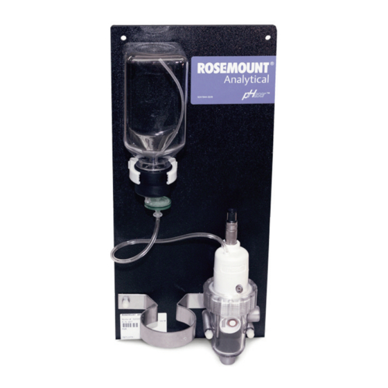
April 2017 LIQ-MAN-3200HP Figure 2-2: Rosemount 3200HP Putting the Rosemount 3200HP Sensor in Service Wire the cable to the transmitter. See the wiring diagrams in the wiring section. Start the sample flow to fill the flow cell with water. Unscrew the plastic nut on the flow cell and slip the nut over the sensor. See Figure 2-1. - Page 11 60° from vertical. Watch for bubbles leaving the port. Bleed an additional 2 mL of solution after the last bubble has escaped. Tighten the bleed screw. Figure 2-4: Rosemount 3200HP Figure 2-3: Rosemount 3200HP Figure 2-5: Rosemount 3200HP...
- Page 12 April 2017 LIQ-MAN-3200HP Connect the VP cable to the sensor. The sensor Figure 2-7: Rosemount 3200HP connector is keyed to ensure proper mating with the cable receptacle. Once the key has slid into the mating slot, hand tighten the connection by turning the knurled ring clockwise.
-
Page 13: Section 3: Wiring
LIQ-MAN-3200HP April 2017 Section 3: Wiring Wiring for Rosemount 3200HP The Rosemount 3200HP sensor is available with Variopol (VP) quick disconnect cable only. For other wiring diagrams not shown below, please refer to the Liquid Transmitter Wiring Diagrams. Table 3-1: VP6 and VP8 Cable Cable Length 10 ft. - Page 14 Wiring Instruction Manual April 2017 LIQ-MAN-3200HP Figure 3-2: Rosemount 3200HP Sensor Wiring to Rosemount 1057 Transmitter Installation...
- Page 15 Instruction Manual Wiring LIQ-MAN-3200HP April 2017 Figure 3-3: Rosemount 3200HP Sensor Wiring to Rosemount 1066 Transmitter Figure 3-4: Rosemount 3200HP Sensor Wiring to Rosemount 5081 Transmitter Installation...
- Page 16 Wiring Instruction Manual April 2017 LIQ-MAN-3200HP Installation...
-
Page 17: Section 4: Calibration
Instruction Manual Calibration LIQ-MAN-3200HP April 2017 Section 4: Calibration Calibration Select two stable buffer solutions. Ideally, the calibration buffers should bracket the expected pH of the sample and be at least two pH units apart. Use the ring at the bottom of the back plate to hold the beaker containing the buffer. - Page 18 Calibration Instruction Manual April 2017 LIQ-MAN-3200HP Calibration...
-
Page 19: Section 5: Maintenance
Instruction Manual Maintenance LIQ-MAN-3200HP April 2017 Section 5: Maintenance Replacing the Electrolyte Solution (PN 9210391) The reference electrolyte solution should last two to three months. To replace the electrolyte solution: Remove the reservoir bottle from the clip on the back plate. Turn the bottle upright. Unscrew the cap without disconnecting the filter or electrolyte tube. - Page 20 Maintenance Instruction Manual April 2017 LIQ-MAN-3200HP Fill the reference junction port with electrolyte solution or deionized water until the level slightly overflows the port. Place the new capillary disc with the sealing O-ring facing down in the port. Use your finger tips –...
-
Page 21: Section 6: Troubleshooting
1. Remove air bubbles. Refer to step 11 in the Putting the error blocking flow or the inside membrane on Rosemount 3200HP Sensor in Service (Section 2.3). the capillary disc is fouled with biological 2. Discard the fill solution in the reservoir and sensor. Rinse the growth. - Page 22 Troubleshooting Instruction Manual April 2017 LIQ-MAN-3200HP Troubleshooting...
-
Page 23: Section 7: Accessories
Instruction Manual Accessories LIQ-MAN-3200HP April 2017 Section 7: Accessories Accessories Table 7-1: Accessories for Rosemount 3200HP sensor Part Number Description 24281-00 15 ft. cable with mating VP8 connector 24281-01 25 ft. cable with mating VP8 connector 24281-02 2.5 ft. cable with mating VP8 connector 24281-03 50 ft. - Page 24 Accessories Instruction Manual April 2017 LIQ-MAN-3200HP Accessories...
-
Page 25: Ec Declaration Of Conformity
Instruction Manual EC Declaration of Conformity LIQ-MAN-3200HP April 2017 EC Declaration of Conformity Note: Please see website for most recent Declaration. EC Declaration of Conformity... - Page 26 EC Declaration of Conformity Instruction Manual April 2017 LIQ-MAN-3200HP EC Declaration of Conformity...
-
Page 27: Intrisicallly Safe Sensor Installation Drawing - Fm
Instruction Manual FM Installation LIQ-MAN-3200HP April 2017 Intrisicallly Safe Sensor Installation Drawing - FM FM Installation... - Page 28 ©2017 Emerson. All rights reserved. Emerson The Emerson logo is a trademark and service mark of Emerson Electric Co. Rosemount is a mark of 8200 Market Blvd. one of the Emerson family of companies. All other marks are the property of their respective Chanhassen, MN 55317, owners.
Need help?
Do you have a question about the Rosemount 3200HP and is the answer not in the manual?
Questions and answers