
Related Manuals for Emerson Rosemount 385+ -02


Summary of Contents for Emerson Rosemount 385+ -02
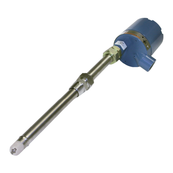
- Page 1 Reference Manual 00809-0100-3386 Rev. AA February 2019 ™ Rosemount 385+ pH/ORP Sensors...
- Page 2 hasgkas...
- Page 3 Essential Instructions Read this page before proceeding! Emerson designs, manufactures and tests its products to meet many national and international stan- dards. Because these sensors are sophisticated technical products, you MUST properly install, use, and maintain them to ensure they continue to operate within their normal specifications. The following instructions MUST be adhered to and integrated into your safety program when installing, using, and maintaining Rosemount products.
-
Page 5: Table Of Contents
Reference Manual Table of Contents 00809-0100-3386 February 2019 Contents Section 1: Description and Specifications Features and Applications ..................1 Performance and Specifications ................2 Ordering Information...................3 Product Certifications ..................4 Section 2: Installation Unpacking and Inspection ...................5 Mechanical Installation ..................5 Electrical Installation..................10 Section 3: Startup and Calibration Startup ......................17 pH Calibration Using Buffer Solutions or Grab Samples ........17 ORP Calibration ....................17... - Page 6 Table of Contents Reference Manual February 2019 00809-0100-3386 Table of Contents...
-
Page 7: Section 1: Description And Specifications
Reference Manual Description and Specifications 00809-0100-3386 February 2019 Section 1: Description and Specifications • SMART enabled • Retractable version allows removal and replacement under pressure without process shut- down. • Long-life, triple junction reference electrode provides longer service life in applications where poisoning ions are present. -
Page 8: Performance And Specifications
Description and Specifications Reference Manual February 2019 00809-0100-3386 Performance and Specifications Table 1-1: Percent linearity over pH pH Range Option 10 Option 11 0-2 pH 2-12 pH 12-13 pH 13-14 pH Table 1-2: Rosemount 385+ sensor specifications Measured Range pH range 0 to 14 pH, GPHT ACCUGLASS ORP range -1500 mV to 1500 mV... -
Page 9: Ordering Information
Reference Manual Description and Specifications 00809-0100-3386 February 2019 Ordering Information Table 1-3: Rosemount 385+ ordering information Model Sensor type 385+ pH/ORP Sensor Body Configuration Retractable with Sensor Head Junction Box, Preamplifier, and Process Connector (1) (2) Insertion/Submersion with Integral Preamplifier and 25 ft. (7.6m) Cable Insertion/Submersion for use with Remote Preamplifier and 15 ft. -
Page 10: Product Certifications
Description and Specifications Reference Manual February 2019 00809-0100-3386 Product Certifications Please see online certificates for further details. IECEx Sensors without preamp (pH and ORP) – Ex ia IIC T4 Ga (-20°C ≤ Ta ≤ +60°C) Sensors with preamp (pH only) – Ex ia IIC T4 Ga (-20°C ≤ Ta ≤ +60°C) Sensors with standard preamp (ORP only) –... -
Page 11: Section 2: Installation
Reference Manual Installation 00809-0100-3386 February 2019 Section 2: Installation Unpacking and Inspection Inspect the outside of the carton for any damage. If damage is detected, contact the carrier immediately. Inspect the instrument and hardware. Make sure all items in the packing list are present and in good condition. - Page 12 Installation Reference Manual February 2019 00809-0100-3386 With the male connector on the sensor’s body, insert the sensor into the ball valve until it gently touches the closed valve. The molded electrode guard will protect the glass bulb from breakage. Thread the male connector body tightly into the ball valve assembly. DO NOT tighten the hex nut on the male connector body;...
- Page 13 Reference Manual Installation 00809-0100-3386 February 2019 Figure 2-1: Typical Mounting Details-Retraction Version Figure 2-2: Dimensional Drawing Retraction Version (Code 02) Installation...
- Page 14 Installation Reference Manual February 2019 00809-0100-3386 Figure 2-3: Dimensional Drawing Submersion/Insertion Version (Code -03, -04) Figure 2-4: Submersion Accessory (Code 03, 04) Installation...
- Page 15 Reference Manual Installation 00809-0100-3386 February 2019 Figure 2-5: Submersion Installations, Handrail Mounting Assembly (P/N 11275-01) Installations...
-
Page 16: Electrical Installation
Installation Reference Manual February 2019 00809-0100-3386 Electrical Installation Make electrical connections as shown on Figures 2-6 through 2-14 using the following guidelines: Pay particular attention to the analyzer or transmitter model number when following details on the wiring diagrams to ensure that the connections are made to the proper terminals. - Page 17 Reference Manual Installation 00809-0100-3386 February 2019 Figure 2-7: Rosemount 385+-03 Sensor Wiring to Rosemount 5081 Transmitter Figure 2-8: Rosemount 385+-04 Sensor Wiring to Rosemount 5081 Transmitter Installation...
- Page 18 Installation Reference Manual February 2019 00809-0100-3386 Figure 2-9: Rosemount 385+-02 sensor Wiring to Rosemount 1056/56/1057 Transmitters Figure 2-10: Rosemount 385+-03 Sensor Wiring to Rosemount 1056/56/1057 Transmitters Installation...
- Page 19 Reference Manual Installation 00809-0100-3386 February 2019 Figure 2-11: Rosemount 385+-04 Sensor Wiring to Rosemount 1056/56/1057 Transmitters Figure 2-12: Wiring Details - Submersion/Insertion (Code 03 & 04) Installation...
- Page 20 Installation Reference Manual February 2019 00809-0100-3386 Figure 2-13: Wiring Rosemount 385+-02 Sensor to Rosemount 1055-11-22-32 through Remote Junction Box Figure 2-14: Wiring Retraction Version (Code-02) Installation...
- Page 21 Reference Manual Installation 00809-0100-3386 February 2019 Figure 2-15: Wiring Details - Remote J-Box for Extension Cable Installation...
- Page 22 Installation Reference Manual February 2019 00809-0100-3386 Figure 2-16: Wiring Details - Remote J-Box with Preamp Installation...
-
Page 23: Section 3: Startup And Calibration
Reference Manual Startup and Calibration 00809-0100-3386 February 2019 Section 3: Startup and Calibration Startup To obtain best accuracy, the sensor must be calibrated as a loop with the transmitter. Please refer to the transmitter manual for proper calibration and setup procedures. Example of 1056 start-up shown below. - Page 24 Startup and Calibration Reference Manual February 2019 00809-0100-3386 3.3.2 Ferric-Ferrous Ammonium Sulfate Solution Although this solution is not as easy to prepare as the quinhydrone solution in Section 3.3.1, it offers a much more stable solution which will maintain its millivolt value for approximately one year when stored in a glass container.
-
Page 25: Section 4: Maintenance
Reference Manual Maintenance 00809-0100-3386 February 2019 Section 4: Maintenance Maintenance The Rosemount 385+ Sensor is a disposal type sensor and therefore requires only periodic cleaning and calibration. If the sensor has failed, it should be discarded and replaced. Sensor Removal Please refer to the appropriate paragraph for instructions regarding removal of the sensor for periodic maintenance. -
Page 26: Ph Electrode Cleaning
Maintenance Reference Manual February 2019 00809-0100-3386 4.2.2 Insertion/Submersion Version (Code -03 and -04 ) WARNING Before removing the sensor, be absolutely certain that the process pressure is reduced to 0 psig and the process temperature is lowered to a safe level! Remove the sensor from process for cleaning, calibration or replacement. -
Page 27: Sensor Tube Replacement (Code -02)
Reference Manual Maintenance 00809-0100-3386 February 2019 Sensor Tube Replacement (Code -02) Replacement of the retraction versions sensor tube assembly involves the removal and installation of two sets of male connectors; one at the process end of the sensor, and the other at the junction box end. - Page 28 Maintenance Reference Manual February 2019 00809-0100-3386 Connect the sensor wires to the terminals on the printed circuit board in the junction box in the manner recommended on the junction box cover, or see Figure 2-4. Reattach the BNC connector to the preamp. Screw on the cover of the junction box. Insert the sensor in the process fitting.
- Page 29 Reference Manual Maintenance 00809-0100-3386 February 2019 Figure 4-2: Male Connector Tightening Diagram Maintenance...
- Page 30 Maintenance Reference Manual February 2019 00809-0100-3386 Maintenance...
-
Page 31: Section 5: Diagnostics And Troubleshooting
Reference Manual Diagnostics and Troubleshooting 00809-0100-3386 February 2019 Section 5: Diagnostics and Troubleshooting Model 54/3081 pH Diagnostics The Models 54 and 54e Transmitters and Models 3081, 4081, and 5081 pH Transmitters automaically search for fault conditions that would cause an error in the measured pH value. Refer to the respective manual for a complete description of the transmitter’s fault conditions. -
Page 32: Rosemount 1056/1057 Smart Ph Diagnostics
Diagnostics and Troubleshooting Reference Manual February 2019 00809-0100-3386 Rosemount 1056/1057 SMART pH Diagnostics Rosemount 1056 and 1057 transmitters automatically search for SMART sensors. Once the SMART sensor is detected, 385+ (-03), and communication is established the start-up, screen will appear, figure 5-1. - Page 33 Reference Manual Diagnostics and Troubleshooting 00809-0100-3386 February 2019 Please refer to the corresponding installment manual for detailed description. The factory calibration data can be found on the bottom of Calibration History menu figure 5-2. Use key-pad to scroll down to the bottom, find Factory Cal. line and press enter.
- Page 34 Diagnostics and Troubleshooting Reference Manual February 2019 00809-0100-3386 Diagnostics and Troubleshooting...
-
Page 35: Section 6: Accessories
Reference Manual Accessories 00809-0100-3386 February 2019 Section 6: Accessories Accessories Table 6-1: Accessories for Rosemount 385+ sensor Part Number Description 11275-01 Handrail mounting assembly (Code 03, 04 only) 23550-00 Remote J-Box without preamplifier (Code 02, 03 only) 23555-00 Remote J-Box with preamplifier, (Code 04 only) 23166-00 Process connector, 316SS, insertion/submersion 1 in. - Page 36 Accessories Reference Manual February 2019 00809-0100-3386 Accessories...
-
Page 37: Ec Declaration Of Conformity
Reference Manual EU Declaration of Conformity 00809-0100-3386 February 2019 EU Declaration of Conformity Note: Please see website for most recent Declaration. EU Declaration of Conformity... - Page 38 EU Declaration of Conformity Reference Manual February 2019 00809-0100-3386 EU Declaration of Conformity...
- Page 39 Reference Manual EU Declaration of Conformity 00809-0100-3386 February 2019 EU Declaration of Conformity...
- Page 40 China RoHS Table Reference Manual February 2019 00809-0100-3386 China RoHS Table...
-
Page 41: Intrisicallly Safe Sensor Installation Drawing - Fm
Reference Manual FM Installation 00809-0100-3386 February 2019 Intrinsically Safe Sensor Installation Drawing - FM FM Installation... - Page 42 ©2019 Emerson. All rights reserved. Emerson The Emerson logo is a trademark and service mark of Emerson Electric Co. Rosemount is a mark of 8200 Market Blvd. one of the Emerson family of companies. All other marks are the property of their respective Chanhassen, MN 55317, owners.
Need help?
Do you have a question about the Rosemount 385+ -02 and is the answer not in the manual?
Questions and answers