Table of Contents
Advertisement
Quick Links
Advertisement
Table of Contents

Related Manuals for Supero X9DRL-EF


Summary of Contents for Supero X9DRL-EF
- Page 1 X9DRL-7F X9DRL-EF USER’S MANUAL Revision 1.0...
- Page 2 The information in this User’s Manual has been carefully reviewed and is believed to be accurate. The vendor assumes no responsibility for any inaccuracies that may be contained in this document, and makes no commitment to update or to keep current the information in this manual, or to notify any person or organization of the updates.
-
Page 3: About This Motherboard
PC users. It provides information for the installation and use of the X9DRL-7F/X9DRL-EF motherboard. About This Motherboard The Super X9DRL-7F/X9DRL-EF motherboard supports dual Intel E5-2600 Series Processors (Socket R) that offer QPI (Intel QuickPath Interface) Technology (V.1.1), providing point-to-point connection with a transfer speed of up to 8.0 GT/s. With the PCH C602J built in, the X9DRL-7F/EF motherboard supports Intel®... -
Page 4: Conventions Used In The Manual
X9DRL-7F/X9DRL-EF Motherboard User’s Manual Conventions Used in the Manual Pay special attention to the following symbols for proper system installation: Warning: Important information given to ensure proper system installation or to prevent damage to the components or injury to yourself;... -
Page 5: Contacting Supermicro
Preface Contacting Supermicro Headquarters Address: Super Micro Computer, Inc. 980 Rock Ave. San Jose, CA 95131 U.S.A. Tel: +1 (408) 503-8000 Fax: +1 (408) 503-8008 Email: marketing@supermicro.com (General Information) support@supermicro.com (Technical Support) Web Site: www.supermicro.com Europe Address: Super Micro Computer B.V. Het Sterrenbeeld 28, 5215 ML 's-Hertogenbosch, The Netherlands Tel:... -
Page 6: Table Of Contents
X9DRL-7F/X9DRL-EF Motherboard User’s Manual Table of Contents Preface Chapter 1 Overview Overview ......................1-1 Processor and Chipset Overview..............1-11 Special Features ................... 1-12 PC Health Monitoring ..................1-12 ACPI Features ....................1-13 Power Supply ....................1-13 Advanced Power Management ..............1-14... - Page 7 Table of Contents Front Control Panel Pin Definitions............... 2-23 NMI Button ....................2-23 Power LED ....................2-23 HDD LED ....................2-24 NIC1/NIC2 LED Indicators ............... 2-24 Overheat (OH)/Fan Fail/PWR Fail/UID LED ..........2-25 Power Fail LED ..................2-25 Reset Button ................... 2-26 Power Button ...................
- Page 8 X9DRL-7F/X9DRL-EF Motherboard User’s Manual 2-10 I-SATA/L-SAS Connections ................2-41 I-SATA (SATA) Ports ................. 2-41 L-SAS Ports (X9DRL-7F Only)..............2-41 Chapter 3 Troubleshooting Troubleshooting Procedures ................3-1 Technical Support Procedures ................ 3-4 Battery Removal and Installation ..............3-6 Battery Removal ....................3-6 Proper Battery Disposal ..................
-
Page 9: Chapter 1 Overview
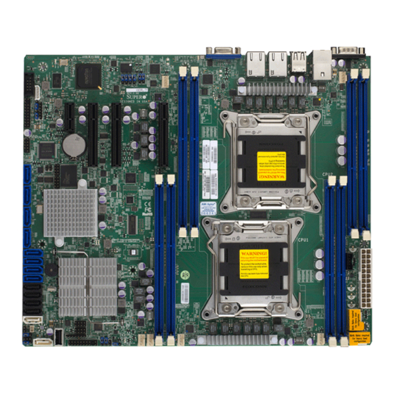
If anything listed here is damaged or missing, contact your retailer. The following items are included in the retail box. • One (1) Supermicro Mainboard • Six (6) Serial ATA cables (CBL-0044Lx6) (for X9DRL-EF) • Eight (8) Serial ATA cables (CBL-0044Lx8) (for X9DRL-7F) • One (1) I/O Shield (MCP-260-00042-0N) •... - Page 10 X9DRL-7F/X9DRL-EF Motherboard User’s Manual Motherboard Image Note: All graphics shown in this manual were based upon the latest PCB Revision available at the time of publishing of the manual. The motherboard you've received may or may not look exactly the same as the graphics...
-
Page 11: Motherboard Layout
Chapter 1: Overview Motherboard Layout USB6/7 USB8/9 COM1 JCOM2 CTRL CTRL LAN2 LAN1 IPMI_LAN JSTBY1 CPU2 Battery 6-SGPIO2 X9DRL-7F/EF Rev.1.01 6-SGPIO1 LSI 2208 CTRL JMLED1 L-SAS4 L-SAS5 BIOS L-SAS6 L-SAS7 Intel PCH I-SATA5 FAN1 I-SATA4 I-SATA3 JBT1 I-SATA2 JSD1 T-SGPIO1 USB4 CPU1 T-SGPIO2... - Page 12 X9DRL-7F/X9DRL-EF Motherboard User’s Manual X9DRL-7F/X9DRL-EF Quick Reference USB6/7 USB8/9 COM1 JCOM2 CTRL CTRL LAN2 LAN1 IPMI_LAN JSTBY1 CPU2 Battery 6-SGPIO2 X9DRL-7F/EF Rev.1.01 6-SGPIO1 LSI 2208 CTRL JMLED1 L-SAS4 L-SAS5 BIOS L-SAS6 L-SAS7 Intel PCH I-SATA5 FAN1 I-SATA4 I-SATA3 JBT1 I-SATA2...
- Page 13 Chapter 1: Overview X9DRL-7F/X9DRL-EF Jumpers Jumper Description Default Setting JBT1 Clear CMOS See Chapter 3 C1/JI SMB to PCI-E Slots Off (Disabled) JPB1 BMC Enable Pins 1-2 (Enabled) JPG1 VGA Enable Pins 1-2 (Enabled) JPL1/JPL2 GLAN1/GLAN2 Enable Pins 1-2 (Enabled)
- Page 14 X9DRL-7F/X9DRL-EF Motherboard User’s Manual (T-)SGPIO1/2 Seria_Link General Purpose I/O Headers 1/2 (for SATA ports) Internal Speaker/Buzzer (FP) USB 4 Front Panel Type A USB Connector 4 (FP) USB 0/1 FP-Accessible USB Connectors 0/1 (BP) USB 6/7, 8/9 Backpanel USB Ports 6/7, 8/9...
-
Page 15: Motherboard Features
Chapter 1: Overview Motherboard Features • Dual Intel E5-2600 Series Processors (Socket R- ® LGA 2011); each processor supports two full-width Intel QuickPath Interconnect (QPI) links (8.0 GT/s one direction per QPI) up to 130W • Memory Integrated memory controller supports: 1. - Page 16 X9DRL-7F/X9DRL-EF Motherboard User’s Manual IPMI 2.0 • IPMI 2.0 supported by the WPCM450 BMC Serial (COM) Port • Two (2) Fast UART 16550 Connections: 9-pin RS- 232 port Peripheral USB Devices Devices • Four (4) USB ports on the rear I/O panel (USB 6/7, USB 8/9), •...
- Page 17 Chapter 1: Overview • SuperDoctor® III, Watch Dog, NMI • Chassis Intrusion Header and Detection • Dimensions 10.00" (L) x 12.00" (W) (254.00 mm x 304.80 mm) Note 1: CPU Maximum Thermal Design Power (TDP) is subject to chassis and heatsink cooling restrictions. For proper thermal management, please check the chassis and heatsink specifications for proper CPU TDP sizing.
-
Page 18: System Block Diagram
X9DRL-7F/X9DRL-EF Motherboard User’s Manual 2208 CPU1 CPU0 Socket 01 Socket 00 E5-2600 E5-2600 Fan x6 NCT7904D PCI-E 2.0 x1 PEG[7] SATA GEN 3 PEG[1:4] PCI-E 2.0 x4(in x8) PCH C602J PCIE 2.0 x1 RJ45 PEG[5] i210 SATA GEN 2 PCIE 2.0 x1... -
Page 19: Processor And Chipset Overview
Processor and Chipset Overview Built upon the functionality and the capability of the Intel E5-2600 Series Proces- sors (Socket R) and the PCH C602J chipset, the X9DRL-7F/X9DRL-EF mother- board provides the performance and feature sets required for dual processor- based high-end servers. -
Page 20: Special Features
X9DRL-7F/X9DRL-EF Motherboard User’s Manual Special Features Recovery from AC Power Loss The Basic I/O System (BIOS) provides a setting that determines how the system will respond when AC power is lost and then restored to the system. You can choose for the system to remain powered off (in which case you must press the power switch to turn it back on), or for it to automatically return to the power-on state. -
Page 21: Acpi Features
It is even more important for processors that have high CPU clock rates. The X9DRL-7F/X9DRL-EF motherboard accommodates 24-pin ATX power supplies. Although most power supplies generally meet the specifications required by the CPU, some are inadequate. In addition, two 12V 8-pin power connections are also required to ensure adequate power supply to the system. -
Page 22: Advanced Power Management
X9DRL-7F/X9DRL-EF Motherboard User’s Manual It is strongly recommended that you use a high quality power supply that meets ATX power supply Specification 2.02 or above. It must also be SSI compliant. (For more information, please refer to the website at http://www.ssiforum.org/). Additionally, in areas where noisy power transmission is present, you may choose to install a line filter to shield the computer from noise. -
Page 23: Other Features Supported By The Wpcm450 Bmc Controller
Chapter 1: Overview The WPCM450 communicates with onboard components via six SMBus interfaces, PECI (Platform Environment Control Interface) buses, and General Purpose I/O ports. Other Features Supported by the WPCM450 BMC Controller The WPCM450 supports the following features: • IPMI 2.0 •... - Page 24 X9DRL-7F/X9DRL-EF Motherboard User’s Manual Notes 1-16...
-
Page 25: Chapter 2 Installation
Chapter 2: Installation Chapter 2 Installation Standardized Warning Statements The following statements are industry-standard warnings, provided to warn the user of situations which have the potential for bodily injury. Should you have questions or experience difficulty, contact Supermicro's Technical Support department for assis- tance. - Page 26 X9DRL-7F/X9DRL-EF Motherboard User’s Manual Attention Danger d'explosion si la pile n'est pas remplacée correctement. Ne la remplacer que par une pile de type semblable ou équivalent, recommandée par le fabricant. Jeter les piles usagées conformément aux instructions du fabricant. ¡Advertencia! Existe peligro de explosión si la batería se reemplaza de manera incorrecta.
-
Page 27: Product Disposal
Chapter 2: Installation Product Disposal Warning! Ultimate disposal of this product should be handled according to all national laws and regulations. 製品の廃棄 この製品を廃棄処分する場合、 国の関係する全ての法律 ・ 条例に従い処理する必要が あります。 警告 本产品的废弃处理应根据所有国家的法律和规章进行。 警告 本產品的廢棄處理應根據所有國家的法律和規章進行。 Warnung Die Entsorgung dieses Produkts sollte gemäß allen Bestimmungen und Gesetzen des Landes erfolgen. -
Page 28: Static-Sensitive Devices
X9DRL-7F/X9DRL-EF Motherboard User’s Manual القىانين واللىائح الىطنية جميع وفقا ل ينبغي التعامل معه هذا المنتج من التخلص النهائي عند 경고! 이 제품은 해당 국가의 관련 법규 및 규정에 따라 폐기되어야 합니다. Waarschuwing De uiteindelijke verwijdering van dit product dient te geschieden in overeenstemming met alle nationale wetten en reglementen. -
Page 29: Processor And Heatsink Installation
Chapter 2: Installation Processor and Heatsink Installation Warning: When handling the processor package, avoid placing direct pressure on the label area. Notes: Always connect the power cord last, and always remove it before adding, removing or changing any hardware components. Make sure that you in- stall the processor into the CPU socket before you install the CPU heatsink. - Page 30 X9DRL-7F/X9DRL-EF Motherboard User’s Manual 2. Press the second load lever labeled 'Close 1st' to release the load plate that covers the CPU socket from its locking position. Pull lever away from Press down on Load the socket Lever 'Close 1st' 3.
- Page 31 Chapter 2: Installation 1. Use your thumb and the index finger to loosen the lever and open the load plate. 2. Using your thumb and index finger, hold the CPU on its edges. Align the CPU keys, which are semi-circle cutouts, against the socket keys. Socket Keys CPU Keys 3.
- Page 32 X9DRL-7F/X9DRL-EF Motherboard User’s Manual 4. With the CPU inside the socket, inspect the four corners of the CPU to make sure that the CPU is properly installed. 5. Close the load plate with the CPU inside the socket. Lock the lever labelled 'Close 1st' first, then lock the lever labelled 'Open 1st' second.
-
Page 33: Installing A Passive Cpu Heatsink
Chapter 2: Installation Installing a Passive CPU Heatsink 1. Do not apply any thermal grease to the heatsink or the CPU die -- the re- quired amount has already been applied. 2. Place the heatsink on top of the CPU so that the four mounting holes are aligned with those on the Motherboard and the Heatsink Bracket underneath. -
Page 34: Removing The Heatsink
X9DRL-7F/X9DRL-EF Motherboard User’s Manual Removing the Heatsink Warning: We do not recommend that the CPU or the heatsink be removed. However, if you do need to uninstall the heatsink, please follow the instructions below to uninstall the heatsink to prevent damage done to the CPU or the CPU socket. -
Page 35: Installing And Removing The Memory Modules
Chapter 2: Installation Installing and Removing the Memory Modules Note: Check Supermicro's website for recommended memory modules. CAUTION Exercise extreme care when installing or removing DIMM modules to prevent any possible damage. Installing & Removing DIMMs 1. Insert the desired number of DIMMs into the memory slots, starting with DIMM A1. -
Page 36: Memory Modules
X9DRL-7F/X9DRL-EF Motherboard User’s Manual Memory Support for the X9DRL-7F/X9DRL-EF Motherboard The X9DRL-7F/X9DRL-EF Motherboard supports up to 256 GB of DDR3 Regis- tered/Load Reduced ECC or Unbuffered ECC/Non-ECC 1600/1333/1066/800 MHz memory modules in eight DIMM slots. For the latest memory updates, please refer to our website a at http://www.supermicro.com/products/motherboard. - Page 37 Chapter 2: Installation Populating UDIMM ECC-Non ECC Memory Modules Intel E5-2600 Series Processor UDIMM Memory Support Ranks Per Memory Capacity 1 Slot per Channel DIMM & Per DIMM 1DPC Data Width (See the Note below) 1.35V 1.5V SRx8 1066, 1333, 1600 Non-ECC DRx8 1066, 1333, 1600...
- Page 38 X9DRL-7F/X9DRL-EF Motherboard User’s Manual Populating LRDIMM ECC Memory Modules Intel E5-2600 Series Processor LRDIMM Memory Support Ranks Per Memory Capacity 1 Slot Per Channel DIMM & Data Per DIMM 1DPC Width (See the Note Below) 1.35V 1.5V QRx4 (DDP) 16GB...
-
Page 39: Motherboard Installation
Chapter 2: Installation Motherboard Installation All motherboards have standard mounting holes to fit different types of chassis. Make sure that the locations of all the mounting holes for both motherboard and chassis match. Although a chassis may have both plastic and metal mounting fas- teners, metal ones are highly recommended because they ground the motherboard to the chassis. -
Page 40: Installing The Motherboard
X9DRL-7F/X9DRL-EF Motherboard User’s Manual Installing the Motherboard 1. Install the I/O shield into the chassis. 2. Locate the mounting holes on the motherboard. 3. Locate the matching mounting holes on the chassis. Align the mounting holes on the motherboard against the mounting holes on the chassis. -
Page 41: Control Panel Connectors And I/O Ports
Chapter 2: Installation Control Panel Connectors and I/O Ports The I/O ports are color coded in conformance with the PC 99 specification. See the picture below for the colors and locations of the various I/O ports. Back Panel Connectors and I/O Ports X9DRL-7F/EF Rev.1.01 Back Panel I/O Port Locations and Definitions... -
Page 42: Serial Ports
X9DRL-7F/X9DRL-EF Motherboard User’s Manual Serial Ports Serial COM) Ports Pin Definitions Two COM connections (COM1 & Pin # Definition Pin # Definition COM2) are located on the mother- board. COM1 is located on the Back- plane I/O panel. COM2, located close to TPM/Port 80 connector (JTPM1), provides front access support. -
Page 43: Universal Serial Bus (Usb)
Chapter 2: Installation Universal Serial Bus (USB) FP USB (0/1 USB 4) Backplane Pin Definitions USB (6/7, 8/9) Two front accessible Universal Serial Pin Definitions USB 0, 4 USB 1 Bus ports (USB 0/1) and a Type A Pin # Definition Pin # Definition Pin# Definition USB connector (USB3) are located on the motherboard to provide front... -
Page 44: Ethernet Ports
X9DRL-7F/X9DRL-EF Motherboard User’s Manual Ethernet Ports LAN Ports Pin Definition Two Gigabit Ethernet ports (LAN1, Pin# Definition LAN2) are located on the I/O back- P2V5SB SGND plane on the motherboard. In addition, TD0+ Act LED an IPMI_Dedicated LAN is located TD0-... -
Page 45: Unit Identifier Switch/Uid Led Indicators
Chapter 2: Installation Unit Identifier Switch/UID LED UID Button Indicators Pin# Definition A Unit Identifier button (JUIDB), a Ground backplane LED indicator, and a Front Ground Panel UID header are located on the Ground motherboard. The UID button is located Button In next to the VGA port on the backplane. The Rear UID LED indicator (LED1) UID LED Status... -
Page 46: Front Control Panel
X9DRL-7F/X9DRL-EF Motherboard User’s Manual Front Control Panel JF1 contains header pins for various buttons and indicators that are normally lo- cated on a control panel at the front of the chassis. These connectors are designed specifically for use with Supermicro's server chassis. See the figure below for the descriptions of the various control panel buttons and LED indicators. -
Page 47: Front Control Panel Pin Definitions
Chapter 2: Installation Front Control Panel Pin Definitions NMI Button NMI Button Pin Definitions (JF1) The non-maskable interrupt button Pin# Definition header is located on pins 19 and 20 Control of JF1. Refer to the table on the right Ground for pin definitions. Power LED Power LED Pin Definitions (JF1) The Power LED connection is located Pin#... -
Page 48: Hdd Led
X9DRL-7F/X9DRL-EF Motherboard User’s Manual HDD LED HDD LED Pin Definitions (JF1) The HDD LED connection is located Pin# Definition on pins 13 and 14 of JF1. Attach a 3.3V Standby cable here to indicate HDD activ- HD Active ity. See the table on the right for pin definitions. -
Page 49: Overheat (Oh)/Fan Fail/Pwr Fail/Uid Led
Chapter 2: Installation Overheat (OH)/Fan Fail/PWR Fail/ OH/Fan Fail/ PWR Fail/Blue_UID UID LED LED Pin Definitions (JF1) Pin# Definition Connect an LED cable to pins 7 and Red_LED-Cathode/OH/Fan Fail/ 8 of Front Control Panel to use the Power Fail5.5V.SB Overheat/Fan Fail/Power Fail and Blue_UID LED UID LED connections. -
Page 50: Reset Button
X9DRL-7F/X9DRL-EF Motherboard User’s Manual Reset Button Reset Button Pin Definitions (JF1) The Reset Button connection is located Pin# Definition on pins 3 and 4 of JF1. Attach it to a Reset hardware reset switch on the computer Ground case. Refer to the table on the right for pin definitions. -
Page 51: Connecting Cables
Chapter 2: Installation Connecting Cables ATX Power 24-pin Connector Pin Definitions Pin# Definition Pin # Definition Power Connectors +3.3V +3.3V -12V +3.3V A 24-pin main power supply connector(JPW4), and two 8-pin CPU power connectors (JPW1/2) PS_ON are located on the motherboard. These power connectors meet the SSI EPS 12V specification and must be connected to your power supply to provide adequate power to the system. -
Page 52: Fan Headers
X9DRL-7F/X9DRL-EF Motherboard User’s Manual Fan Headers Fan Header Pin Definitions This motherboard has eight system/ Pin# Definition CPU fan headers (Fan 1-Fan 5 and Fan Ground A) on the motherboard. All these 4-pin +12V fans headers are backward compatible Tachometer with the traditional 3-pin fans. However,... -
Page 53: Internal Speaker
Chapter 2: Installation Internal Speaker Internal Buzzer Pin Definition The Internal Speaker (Buzzer) can be Pin# Definitions used to provide audible indications for Pin 1 Pos. (+) Beep In various beep codes. See the table on Pin 2 Neg. (-) Alarm the right for pin definitions. -
Page 54: Tpm/Port 80 Header
X9DRL-7F/X9DRL-EF Motherboard User’s Manual TPM/Port 80 Header TPM/Port 80 Header Pin Definitions A Trusted Platform Module/Port 80 Pin # Definition Pin # Definition header is located at JTPM1 to provide LCLK TPM support and Port 80 connection. LFRAME# <(KEY)> Use this header to enhance system... -
Page 55: Power Smb (I 2 C) Connector
Chapter 2: Installation Power SMB (I C) Connector PWR SMB Pin Definitions Power System Management Bus (I Pin# Definition Connector (JPI C1) monitors power Clock supply, fan and system temperatures. Data See the table on the right for pin PMBUS_Alert definitions. Ground +3.3V IPMB... -
Page 56: T-Sgpio/6-Sgpio Headers
X9DRL-7F/X9DRL-EF Motherboard User’s Manual T-SGPIO/6-SGPIO Headers T-SGPIO/6-SGPIO Headers Pin Definitions Four SGPIO (Serial Link General Pin# Definition Definition Purpose Input/Output) headers are located on the motherboard. T-SGPIO Ground Data 1/2 support onboard SATA connec- Load Ground tions on the motherboard. 6-SGPIO... -
Page 57: Jumper Settings
Chapter 2: Installation Jumper Settings Explanation of Jumpers Connector Pins To modify the operation of the mother- board, jumpers can be used to choose between optional settings. Jumpers create Jumper shorts between two pins to change the function of the connector. Pin 1 is identified with a square solder pad on the printed circuit board. -
Page 58: Cmos Clear
X9DRL-7F/X9DRL-EF Motherboard User’s Manual CMOS Clear JBT1 is used to clear CMOS. Instead of pins, this "jumper" consists of contact pads to prevent accidental clearing of CMOS. To clear CMOS, use a metal object such as a small screwdriver to touch both pads at the same time to short the connection. -
Page 59: Vga Enable
Chapter 2: Installation VGA Enable VGA Enable Jumper Settings Jumper JPG1 allows the user to enable Jumper Setting Definition the onboard VGA connector. The default Enabled (Default) setting is 1-2 to enable the connection. Disabled See the table on the right for jumper settings. -
Page 60: I 2 C Bus To Pci-Exp. Slots
X9DRL-7F/X9DRL-EF Motherboard User’s Manual C Bus to PCI-Exp. Slots C for PCI-E slots Jumper Settings Use Jumpers JI C1 and JI C2 to connect Jumper Setting Definition the System Management Bus (I C) to Closed Enabled (Default) PCI-Express slots to improve PCI per-... -
Page 61: Onboard Led Indicators
Chapter 2: Installation Onboard LED Indicators Link LED Activity LED GLAN LEDs There are two GLAN ports on the moth- Rear View (when facing the erboard. Each Gigabit Ethernet LAN port rear side of the chassis) has two LEDs. The Yellow LED on the GLAN Activity Indicator (Right) LED Settings right indicates activity. -
Page 62: Onboard Power Led
X9DRL-7F/X9DRL-EF Motherboard User’s Manual Onboard Power LED Onboard PWR LED Indicator LED States An Onboard Power LED is located at LED Color Definition LED2 on the motherboard. When this System Off (PWR cable not connected) LED is on, the system is on. Be sure to... -
Page 63: L-Sas Activity Led (X9Drl-7F Only)
Chapter 2: Installation L-SAS Activity LED (X9DRL-7F Only) L-SAS Activity LED Status A L-SAS Activity LED is located at Color/State Definition JMLED1 on the motherboard. When Green: Blinking L-SAS: Active JMLED1 is blinking, L-SAS is working L-SAS: Disabled or Failed properly. -
Page 64: Sata Activity Led
X9DRL-7F/X9DRL-EF Motherboard User’s Manual SATA Activity LED SATA Activity LED Status A SATA Activity LED is located at JLED1 Color/State Definition on the motherboard. When JLED1 is Green: Blinking SATA: Active blinking, SATA is working properly. SATA: Disabled or Failed Note: Refer to Page 2-25 for information on the rear UID LED (LED1). -
Page 65: 2-10 I-Sata/L-Sas Connections
Chapter 2: Installation 2-10 I-SATA/L-SAS Connections I-SATA (SATA) Ports I-SATA/L-SAS Pin Definitions There are two SATA 3.0 (I-SATA 0/1) and four SATA 2.0 Pin# Definition ports (I-SATA2-I-SATA5 located on the motherboard. Ground These SATA ports, supported by Intel PCH, provide TX_P serial-link signal connections, which are faster than the TX_N connections of Parallel ATA. - Page 66 X9DRL-7F/X9DRL-EF Motherboard User’s Manual Notes 2-42...
-
Page 67: Chapter 3 Troubleshooting
Chapter 3: Troubleshooting Chapter 3 Troubleshooting Troubleshooting Procedures Use the following procedures to troubleshoot your system. If you have followed all of the procedures below and still need assistance, refer to the ‘Technical Support Procedures’ and/or ‘Returning Merchandise for Service’ section(s) in this chapter. Note: Always disconnect the power cord before adding, changing or installing any hardware components. -
Page 68: System Boot Failure
X9DRL-7F/X9DRL-EF Motherboard User’s Manual No Video 1. If the power is on, but you have no video, remove all the add-on cards and cables. 2. Use the speaker to determine if any beep codes exist. Refer to Appendix A for details on beep codes. -
Page 69: Memory Errors
Chapter 3: Troubleshooting Memory Errors When a No-Memory Beep Code is issued by the system, check the following: 1. Make sure that the memory modules are compatible with the system and that the DIMM modules are properly and fully installed. (For memory compatibility, refer to the Memory Compatibility Chart posted on our website @ http://www. -
Page 70: Technical Support Procedures
X9DRL-7F/X9DRL-EF Motherboard User’s Manual tings in the BIOS to make sure that the CPU and System temperatures are within the normal range. Also check the front panel Overheat LED, and make sure that the Overheat LED is not on. 5. Adequate power supply: Make sure that the power supply provides adequate power to the system. - Page 71 Chapter 3: Troubleshooting through its channels, so it is best to first check with your distributor or reseller for troubleshooting services. They should know of any possible problem(s) with the specific system configuration that was sold to you. 1. Please go through the ‘Troubleshooting Procedures’ and 'Frequently Asked Question' (FAQ) sections in this chapter or see the FAQs on our website (http://www.supermicro.com/) before contacting Technical Support.
-
Page 72: Battery Removal And Installation
X9DRL-7F/X9DRL-EF Motherboard User’s Manual Battery Removal and Installation Battery Removal To remove the onboard battery, follow the steps below: 1. Power off your system and unplug your power cable. 2. Locate the onboard battery as shown below. 3. Using a tool such as a pen or a small screwdriver, push the battery lock out- wards to unlock it. -
Page 73: Frequently Asked Questions
Chapter 3: Troubleshooting Frequently Asked Questions Question: What are the various types of memory that my motherboard can support? Answer: The motherboard supports Registered/Load Reduced ECC or Unbuffered ECC/Non-ECC DDR3 DIMM modules. To enhance memory performance, do not mix memory modules of different speeds and sizes. Please follow all memory installation instructions given on Section 2-4 in Chapter 2. -
Page 74: Returning Merchandise For Service
X9DRL-7F/X9DRL-EF Motherboard User’s Manual Returning Merchandise for Service A receipt or copy of your invoice marked with the date of purchase is required before any warranty service will be rendered. You can obtain service by calling your ven- dor for a Returned Merchandise Authorization (RMA) number. When returning the... -
Page 75: Chapter 4 Bios
BIOS Introduction This chapter describes the AMI BIOS Setup utility for the X9DRL-7F/X9DRL-EF. It also provides the instructions on how to navigate the AMI BIOS Setup utility screens. The AMI ROM BIOS is stored in a Flash EEPROM and can be easily updated. -
Page 76: Starting The Setup Utility
X9DRL-7F/X9DRL-EF Motherboard User’s Manual Note: For AMI UEFI BIOS Recovery, please refer to the UEFI BIOS Re- covery User Guide posted @http://www.supermicro.com/support/manuals/. Starting the Setup Utility Normally, the only visible Power-On Self-Test (POST) routine is the memory test. As the memory is being tested, press the <Del> key to enter the main menu of the AMI BIOS Setup utility. -
Page 77: 4-3 Advanced Setup Configurations
Chapter 4: AMI BIOS The AMI BIOS main menu displays the following information: System Time/System Date Use this option to change the system time and date. Highlight System Time or System Date using the arrow keys. Enter new values through the keyboard and press <Enter>. -
Page 78: Boot Feature
X9DRL-7F/X9DRL-EF Motherboard User’s Manual Boot Feature Quiet Boot Use this feature to select the bootup screen display between POST messages or the OEM logo. Select Disabled to display the POST messages. Select Enabled to display the OEM logo. The default setting is Enabled. - Page 79 Chapter 4: AMI BIOS to power off when the user presses the power button for 4 seconds or longer. The options are Instant Off and 4 Seconds Override. Restore on AC Power Loss Use this feature to set the power state after a power outage. Select Stay Off for the system power to remain off after a power loss.
- Page 80 X9DRL-7F/X9DRL-EF Motherboard User’s Manual • L2 Cache • L3 Cache CPU Speed This item displays the speed of the CPU installed in a socket specified. 64-bit This item indicates if the CPU installed in the socket specified by the user sup- ports 64-bit technology.
- Page 81 Chapter 4: AMI BIOS Intel® AES-NI Select Enable to use the Intel Advanced Encryption Standard (AES) New In- structions (NI) to ensure data security. The options are Enabled and Disabled. MLC Streamer Prefetcher (Available when supported by the CPU) If set to Enabled, the MLC (mid-level cache) streamer prefetcher will prefetch streams of data and instructions from the main memory to the L2 cache to im- prove CPU performance.
- Page 82 X9DRL-7F/X9DRL-EF Motherboard User’s Manual EIST (Available when Power Technology is set to Custom) EIST (Enhanced Intel SpeedStep Technology) allows the system to automatically adjust processor voltage and core frequency to reduce power consumption and heat dissipation. The options are Disabled (GV3 Disabled), and Enabled (GV3 Enabled).
- Page 83 Chapter 4: AMI BIOS Factory Long Duration Power Limit This item displays the power limit (in watts) set by the manufacturer during which long duration power is maintained. Long Duration Power Limit This item displays the power limit (in watts) set by the user during which long dura- tion power is maintained.
- Page 84 X9DRL-7F/X9DRL-EF Motherboard User’s Manual Ageing Timer Rollover Select Disabled to allow the BIOS to determine how long the system should wait before reallocating resources to PCI-E devices for data transferring when a deadlock occurs. Select 32 us for the BIOS to wait for 32 us second before reallocating system resources for use of PCI-E data transferring when a deadlock occurs.
- Page 85 Chapter 4: AMI BIOS Current QPI Frequency This item displays the current frequency of the QPI Link. Isoc Select Enabled to enable Ischronous support to meet QoS (Quality of Service) requirements. This feature is especially important for virtualization technology. The options are Disabled and Enabled. QPI (Quick Path Interconnect) Link Speed Mode Use this feature to select data transfer speed for QPI Link connections.
- Page 86 X9DRL-7F/X9DRL-EF Motherboard User’s Manual DRAM RAPL Mode RAPL (Running Average Power Limit) provides mechanisms to enforce power consumption limits on supported processors. The options are DRAM RAPL MODE0 , DRAM RAPL MODE1, and Disabled. DDR Speed Use this feature to force a DDR3 memory module to run at a frequency other than what is specified by the manufacturer.
-
Page 87: South Bridge
Chapter 4: AMI BIOS Thermal Throttling Throttling improves reliability and reduces power consumption in the proces- sor via automatic voltage control during processor idle states. The options are Disabled and CLTT (Closed Loop Thermal Throttling). South Bridge This feature allows the user to configure the settings for the Intel PCH chip. PCH Information This feature displays the following PCH information. - Page 88 X9DRL-7F/X9DRL-EF Motherboard User’s Manual SATA Configuration When this submenu is selected, the AMI BIOS automatically detects the presence of IDE or SATA devices and displays the following items. SATA Port0~SATA Port5: The AMI BIOS displays the status of each SATA port as detected by the BIOS.
- Page 89 Chapter 4: AMI BIOS RAID Mode The following items are displayed when RAID Mode is selected: SATA RAID Option ROM/UEFI Driver Select Enabled to boot the system from a SATA RAID device or a UEFI (Unified Extensible Firmware Interface) device. The options are Enabled or Disabled.
- Page 90 X9DRL-7F/X9DRL-EF Motherboard User’s Manual Maximum Read Request Select Auto to allow the system BIOS to automatically set the maximum read request size for a PCI-E device to enhance system performance. The options are Auto, 128 Bytes, 256 Bytes, 512 Bytes, 1024 Bytes, 2048 Bytes, and 4096 Bytes.
- Page 91 Chapter 4: AMI BIOS Network Stack When this featurer is set to Enabled, both PXE (Preboot Execution Environment) and UEFI (Unified Extensible Firmware Interface) will be enabled for network stack support. The options are Enabled and Disabled. Super IO Configuration Super IO Chip Displays the Super IO chip type.
-
Page 92: Serial Port Console Redirection
X9DRL-7F/X9DRL-EF Motherboard User’s Manual SOL (Serial_Over_LAN) Change Settings This option specifies the base I/O port address and the Interrupt Request address of Serial Port 2. The options are Auto, IO=3F8h; IRQ=4; IO=3F8h; IRQ=3; IO=2F8h; IRQ=3; IO=3E8h; IRQ=5; IO=2E8h; IRQ=7; IO=3F8h; IRQ=3, 4, 5, 6, 7, 10, 11, 12;... - Page 93 Chapter 4: AMI BIOS Bits Per Second This item sets the transmission speed for a serial port used in Console Redirec- tion. Make sure that the same speed is used in the host computer and the client computer. A lower transmission speed may be required for long and busy lines. The options are 9600, 19200, 38400, 57600, and 115200 (bits per second).
- Page 94 X9DRL-7F/X9DRL-EF Motherboard User’s Manual Legacy OS Redirection Use this feature to select the number of rows and columns used in Console Redirection for legacy OS support. The options are 80x24 and 80x25. Putty Keypad Use this feature to select function key and keypad setting on Putty. The options are VT100, LINUX, XTERMR6, SCO, ESCN, and VT400.
-
Page 95: Acpi Settings
Chapter 4: AMI BIOS Flow Control This feature allows the user to set the flow control for Console Redirection to prevent data loss caused by buffer overflow. Send a "Stop" signal to stop send- ing data when the receiving buffer is full. Send a "Start" signal to start sending data when the receiving buffer is empty. - Page 96 X9DRL-7F/X9DRL-EF Motherboard User’s Manual High Precision Event Timer Select Enabled to activate the High Precision Event Timer (HPET) that produces periodic interrupts at a much higher frequency than a Real-time Clock (RTC) does in synchronizing multimedia streams, providing smooth playback, reducing the de- pendency on other timestamp calculation devices, such as an x86 RDTSC Instruc- tion embedded in the CPU.
- Page 97 Chapter 4: AMI BIOS Intel TXT(LT-SX) Configuration This feature indicates if the following hardware components support the Intel TXT (Trusted Execution Technology), which helps protect against software-based attacks and ensures protection, confidentiality and integrity of data stored or created on the system. •...
-
Page 98: Event Logs
X9DRL-7F/X9DRL-EF Motherboard User’s Manual Event Logs Use this menu to configure Event Log settings. Change SmBIOS Event Log Settings Enabling/Disabling Options Smbios Event Log Change this item to enable or disable all features of the Smbios Event Logging during boot. The options are Enabled and Disabled. -
Page 99: Ipmi
Chapter 4: AMI BIOS This option erases all logged events. The options are No, Yes, Next reset, and Yes, Every reset. When Log is Full This option automatically clears the Event Log memory of all messages when it is full. The options are Do Nothing and Erase Immediately. Log System Boot Event This option toggles the System Boot Event logging to enabled or disabled. -
Page 100: System Event Log
X9DRL-7F/X9DRL-EF Motherboard User’s Manual System Event Log Enabling/Disabling Options SEL Components Select Enabled for all system event logging at bootup. The options are Enabled and Disabled. Erasing Settings Erase SEL Select 'Yes, On next reset' to erase all system event logs upon next system reboot. - Page 101 Chapter 4: AMI BIOS Subnet Mask This item displays the sub-network that this computer belongs to. The value of each three-digit number separated by dots should not exceed 255. Station MAC Address This item displays the Station Mac address for this computer. Mac addresses are 6 two-digit hexadecimal numbers.
-
Page 102: Boot
X9DRL-7F/X9DRL-EF Motherboard User’s Manual Boot This menu allows the user to configure the following boot settings for the system. Set Boot Priorities 1st Boot Device/2nd Boot Device/3rd Boot Device/4th Boot Device/5th Boot Device/6th Boot Device Use this feature to specify the sequence of boot priority for a device specified by the user. -
Page 103: Security
Chapter 4: AMI BIOS Network Device BBS Priorities This submenu allows the user to specify the boot priority sequence of a network device. 1st Device UEFI Boot Device BBS Priorities This submenu allows the user to specify the boot priority sequence of a UEFI bootable device. -
Page 104: Save & Exit
X9DRL-7F/X9DRL-EF Motherboard User’s Manual Save & Exit This submenu allows the user to configure the Save and Exit settings for the system. Discard Changes and Exit Select this option to quit the BIOS Setup without making any permanent changes to the system configuration, and reboot the computer. Select Discard Changes and Exit, and press <Enter>. - Page 105 Chapter 4: AMI BIOS Discard Changes Select this feature and press <Enter> to discard all the changes and return to the BIOS setup. When the dialog box appears, asking you if you want to load previ- ous values, select Yes to load the values previous saved, or select No to keep the changes you've made so far.
- Page 106 X9DRL-7F/X9DRL-EF Motherboard User’s Manual Notes 4-32...
-
Page 107: Appendix A Bios Error Beep Codes
Appendix A: BIOS POST Error Codes Appendix A BIOS Error Beep Codes During the POST (Power-On Self-Test) routines, which are performed at each system boot, errors may occur. Non-fatal errors are those which, in most cases, allow the system to continue to boot. - Page 108 X9DRL-7F/X9DRL-EF Motherboard User’s Manual Notes...
-
Page 109: Appendix B Software Installation Instructions
Appendix B: Software Installation Instructions Appendix B Software Installation Instructions B-1 Installing Software Programs The Supermicro ftp site contains drivers and utilities for your system at ftp://ftp. supermicro.com. Some of these must be installed, such as the chipset driver. After accessing the ftp site, go into the CDR_Images directory and locate the ISO file for your motherboard. -
Page 110: Configuring Superdoctor Iii
X9DRL-7F/X9DRL-EF Motherboard User’s Manual B-2 Configuring SuperDoctor III The SuperDoctor® III program is a web-based management tool that supports remote management capability. It includes Remote and Local Management tools. The local management is called SD III Client. The SuperDoctor III program allows you to monitor the environment and operations of your system. - Page 111 Appendix B: Software Installation Instructions SuperDoctor® III Interface Display Screen (Remote Control) Note: The SuperDoctor III program and User’s Manual can be downloaded from the Supermicro web site at http://www.supermicro.com/products/ac- cessories/software/SuperDoctorIII.cfm. For Linux, we recommend that you use the SuperDoctor II application instead.
- Page 112 X9DRL-7F/X9DRL-EF Motherboard User’s Manual Notes...
- Page 113 (Disclaimer Continued) The products sold by Supermicro are not intended for and will not be used in life support systems, medical equipment, nuclear facilities or systems, aircraft, aircraft devices, aircraft/emergency communication devices or other critical systems whose failure to perform be reasonably expected to result in significant injury or loss of life or catastrophic property damage.
Need help?
Do you have a question about the X9DRL-EF and is the answer not in the manual?
Questions and answers