Table of Contents
Advertisement
Advertisement
Table of Contents

Related Manuals for Supero X9DRH-7F


Summary of Contents for Supero X9DRH-7F
- Page 1 X9DRH-7F X9DRH-iF X9DRH-7TF X9DRH-iTF USER’S MANUAL Revision 1.0...
- Page 2 The information in this User’s Manual has been carefully reviewed and is believed to be accurate. The vendor assumes no responsibility for any inaccuracies that may be contained in this document, and makes no commitment to update or to keep current the information in this manual, or to notify any person or organization of the updates.
-
Page 3: About This Motherboard
PC users. It provides information for the installation and use of the X9DRH-7F/-iF/-7TF/-iTF motherboard. About This Motherboard The Super X9DRH-7F/-iF/-7TF/-iTF motherboard supports dual Intel E5-2600 Se- ries (Socket R) processors and Intel QPI (QuickPath Interface) Technology (V.1.1), providing point-to-point connections with transfer speeds of up to 8.0 TG/s. With the C602 PCH built in, the X9DRH series motherboard supports Intel®... -
Page 4: Conventions Used In The Manual
X9DRH-7F/-iF/-7TF/-iTF Motherboard User’s Manual Conventions Used in the Manual Pay special attention to the following symbols for proper system installation and to prevent damage to the system or injury to yourself: Danger/Caution: Instructions to be strictly followed to prevent catastrophic... -
Page 5: Contacting Supermicro
Preface Contacting Supermicro Headquarters Address: Super Micro Computer, Inc. 980 Rock Ave. San Jose, CA 95131 U.S.A. Tel: +1 (408) 503-8000 Fax: +1 (408) 503-8008 Email: marketing@supermicro.com (General Information) support@supermicro.com (Technical Support) Website: www.supermicro.com Europe Address: Super Micro Computer B.V. Het Sterrenbeeld 28, 5215 ML 's-Hertogenbosch, The Netherlands Tel:... -
Page 6: Table Of Contents
X9DRH-7F/-iF/-7TF/-iTF Motherboard User’s Manual Table of Contents Preface Chapter 1 Overview Overview ......................1-1 Processor and Chipset Overview..............1-11 Special Features ................... 1-12 PC Health Monitoring ..................1-12 ACPI Features ....................1-13 Power Supply ....................1-13 Super I/O ....................... 1-14 Advanced Power Management ..............1-14 Overview of the Nuvoton WPCM450 Controller ........... - Page 7 C) Connector ..............2-27 IPMB ......................2-27 T-SGPIO1/2/T-SGPIO-S Headers ............2-28 SATA DOM Power Connector ..............2-28 RAID Backup Battery Header (For X9DRH-7F/7TF) ....... 2-29 SAS Battery ....................2-29 Jumper Settings ................... 2-30 Explanation of Jumpers ................2-30 LAN1/LAN2 Enable/Disable ..............2-30 CMOS Clear .....................
- Page 8 X9DRH-7F/-iF/-7TF/-iTF Motherboard User’s Manual System Boot Failure ..................3-2 Losing the System’s Setup Configuration ............3-2 Memory Errors ....................3-3 When the System Becomes Unstable ............3-3 Technical Support Procedures ................ 3-4 Frequently Asked Questions ................3-5 Returning Merchandise for Service..............3-6 Chapter 4 BIOS Introduction ......................
-
Page 9: Chapter 1 Overview
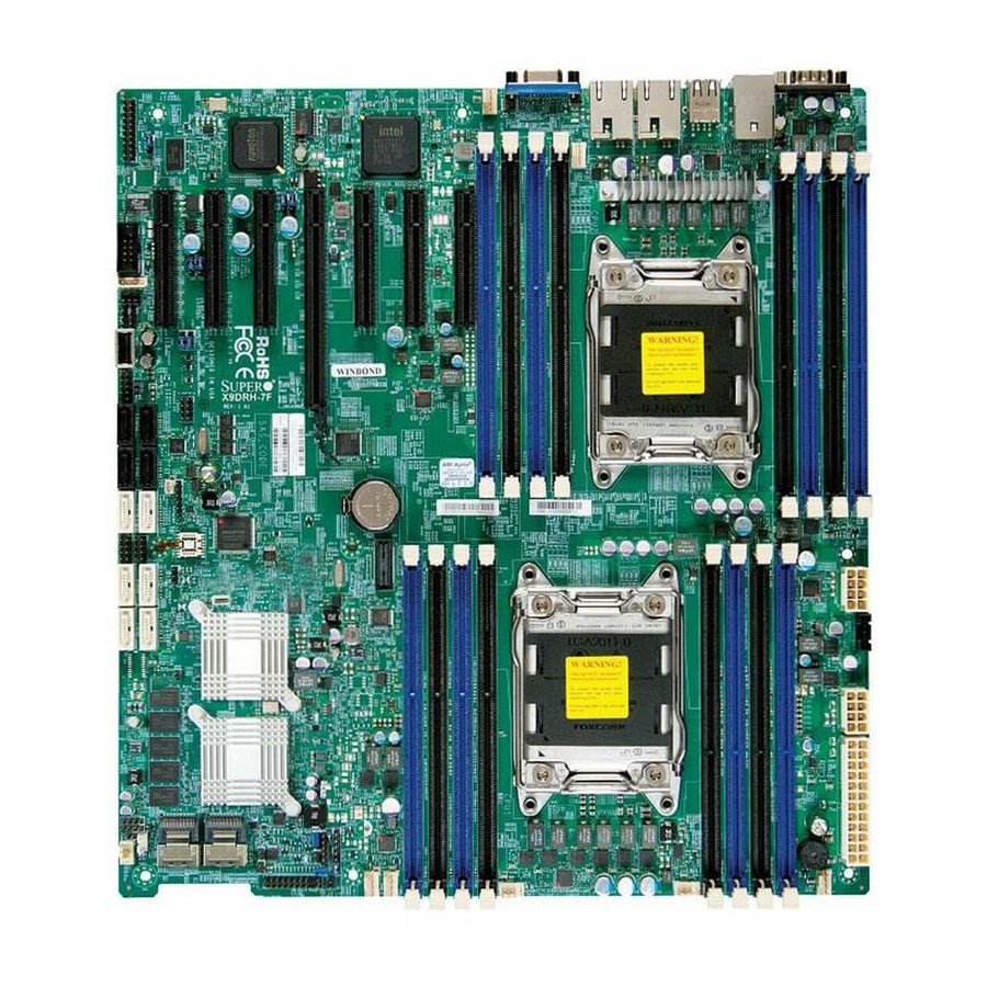
Six (6) Serial ATA cables (CBL-0044Lx6) (for X9DRH-iF/iTF) • Two (2) Serial ATA cables (CBL-0044Lx2) (for X9DRH-7F/7TF) • Two (2) I-Pass to Serial ATA cables (CBL-097L-03) (for X9DRH-7F/7TF) • One (1) I/O Shield Bracket (MCP-260-00042-0N) • One (1) Supermicro CD containing drivers and utilities •... - Page 10 X9DRH-7F/-iF/-7TF/-iTF Motherboard User’s Manual Motherboard Image Note: All graphics shown in this manual were based upon the latest PCB Revision available at the time of publishing of the manual. The motherboard you've received may or may not look exactly the same as the graphics...
-
Page 11: Motherboard Layout
Note 1: LAN1/LAN2 ports support 1G LAN connections on the X9DRH- 7F/-iF, but support 10G connections on the 7TF/iTF models. Note 2: SAS 0~3/SAS 4~7 are available on the X9DRH-7F/-7TF only. Note 3: For the latest CPU/Memory updates, please refer to our website... - Page 12 X9DRH-7F/-iF/-7TF/-iTF Motherboard User’s Manual X9DRH-7F/-iF/-7TF/-iTF Quick Reference USB2/3 USB0/1 COM1 LAN CTRL BMC CTRL FAN5 KB/MS IPMI_LAN LAN1 LAN2 COM2 CLOSE 1st CPU2 OPEN 1st Battery T-SGPIO1 BIOS X9DRH-7F/iF/7TF/iF Rev. 1.01 JITP0 JBT1 Intel IO Hub LEDS1 CLOSE 1st CPU1...
- Page 13 Chapter 1: Overview X9DRH-7F/-iF/-7TF/-iTF Jumpers Jumper Description Default Setting JBT1 Clear CMOS See Chapter 3 C1/JI SMB to PCI-E Slots Pins 2-3 (Normal) JPB1 BMC Enable Pins 1-2 (Enabled) JPG1 VGA Enable Pins 1-2 (Enabled) JPLAN1 LAN1/LAN2 Enable Pins 1-2 (Enabled)
- Page 14 SATA 2.0 Connectors 0~3 from SCU (Storage Control Unit) (Available for RAID 0, 1, 5, 10 when used in conjunction with T-SPGIO-S) SAS 0~3, 4~7 Serial_Attached_SCSI Connectors 0~3, 4~7 (X9DRH-7F/- 7TF) Onboard Buzzer (Internal Speaker) T-SGPIO1 Serial Link General_Purpose IO Headers (used in conjunc-...
-
Page 15: Motherboard Features
Chapter 1: Overview Motherboard Features • Dual Intel E5-2600 Series (Socket R) processors; ® each processor supports two full-width Intel Quick- Path Interconnect (QPI) links (with support of up to 8.0 GT/s per QPI link) • Memory Integrated memory controller supports: •... -
Page 16: Peripheral Devices
X9DRH-7F/-iF/-7TF/-iTF Motherboard User’s Manual SAS Connections (X9DRH-7F/-7TF) • LSI SAS 2208 Controller (w/hardware RAID support) • SAS Ports 0~3, 4~7 • RAID Support RAID 0, 1, 5, 6, 10, 50, 60 (Hardware RAID) IPMI 2.0 • IPMI 2.0 supported by the Novuton BMC (WPCM450) Serial (COM) Port •... - Page 17 Chapter 1: Overview • Thermal Monitor 2 (TM2) support Fan Control • Fan status monitoring with firmware 4-pin (Pulse Width Modulation) fan speed control • Low noise fan speed control LED Indicators • System/CPU Overheat LED • Suspend-state LED • UID/Remote UID LED •...
-
Page 18: System Block Diagram
X9DRH-7F/-iF/-7TF/-iTF Motherboard User’s Manual #H-2 #H-1 #D-2 #G-2 #C-2 #G-1 #C-1 #F-2 #B-2 #F-1 #B-1 #E-2 #A-2 #E-1 E5-2600 E5-2600 #A-1 8 SNB CORE 8 SNB CORE DDR-III DDR-III (CPU1) (CPU2) #3A #3C DMI2 DMI2 PCI-E X16 G3 PCI-E X8 G3... -
Page 19: Processor And Chipset Overview
Chapter 1: Overview Processor and Chipset Overview Built upon the functionality and the capabilities of the Intel E5-2600 Series (Socket R) processor and the C602 PCH, the X9DRH-7F/-iF/-7TF/-iTF motherboard pro- vides the performance and feature sets required for dual_processor-based HPC/ Cluster/Database servers. -
Page 20: Special Features
X9DRH-7F/-iF/-7TF/-iTF Motherboard User’s Manual Special Features Recovery from AC Power Loss Basic I/O System (BIOS) provides a setting that determines how the system will respond when AC power is lost and then restored to the system. You can choose for the system to remain powered off (in which case you must press the power switch to turn it back on), or for it to automatically return to the power-on state. -
Page 21: Acpi Features
Chapter 1: Overview to provide you with warnings when the system temperature, CPU temperatures, voltages and fan speeds go beyond a predefined range. ACPI Features ACPI stands for Advanced Configuration and Power Interface. The ACPI specifica- tion defines a flexible and abstract hardware interface that provides a standard way to integrate power management features throughout a PC system, including its hardware, operating system and application software. -
Page 22: Super I/O
X9DRH-7F/-iF/-7TF/-iTF Motherboard User’s Manual It is strongly recommended that you use a high quality power supply that meets ATX power supply Specification 2.02 or above. It must also be SSI compliant. (For more information, please refer to the website at http://www.ssiforum.org/). Additionally, in areas where noisy power transmission is present, you may choose to install a line filter to shield the computer from noise. -
Page 23: Overview Of The Nuvoton Wpcm450 Controller
Chapter 1: Overview Manageability Engine (ME) The Manageability Engine, which is an ARC controller embedded in the PCH, provides Server Platform Services (SPS) to your system. The services provided by SPS are different from those provided by the ME on client platforms. Overview of the Nuvoton WPCM450 Controller The Nuvoton WPCM450R Controller, a Baseboard Management Controller (BMC), supports 2D/VGA-compatible Graphic Cores with PCI interface, creating multi-media... - Page 24 X9DRH-7F/-iF/-7TF/-iTF Motherboard User’s Manual • Provides remote Hardware Health Monitoring via IPMI. Key features • Provides Network Management Security via remote access/console redirection. • Supports the following Management tools: IPMIView, CLI (Command Line Interface) • RMCP+ protocol supported Note 1: For more information on IPMI configuration, please refer to the IPMI User's Guide posted on our website at http://www.supermicro.com/...
-
Page 25: Chapter 2 Installation
Chapter 2: Installation Chapter 2 Installation Static-Sensitive Devices Electrostatic Discharge (ESD) can damage electronic com ponents. To avoid dam- aging your system board, it is important to handle it very carefully. The following measures are generally sufficient to protect your equipment from ESD. Precautions •... -
Page 26: Processor And Heatsink Installation
X9DRH-7F/-iF/-7TF/-iTF Motherboard User’s Manual Processor and Heatsink Installation Warning: When handling the processor package, avoid placing direct pressure on the label area. Notes: 1. Always connect the power cord last, and always remove it before adding, removing or changing any hardware components. Make sure that you in- stall the processor into the CPU socket before you install the CPU heatsink. - Page 27 Chapter 2: Installation 2. Press the second load lever labeled 'Close 1st' to release the load plate that covers the CPU socket from its locking position. Pull lever away from Press down on Load the the socket Lever labeled 'Close 1st' 3.
- Page 28 X9DRH-7F/-iF/-7TF/-iTF Motherboard User’s Manual 1. Use your index fingers to loosen the lever and open the load plate. 2. Use your thumb and index finger to hold the CPU on its edges. Align the CPU keys, which are semi-circle cutouts, against the socket keys.
- Page 29 Chapter 2: Installation 4. With the CPU inside the socket, inspect the four corners of the CPU to make sure that the CPU is properly installed. 5. Close the load plate with the CPU inside the socket. Lock the lever labeled 'Close 1st' first, then lock the lever labeled 'Open 1st' second.
-
Page 30: Installing A Passive Cpu Heatsink
X9DRH-7F/-iF/-7TF/-iTF Motherboard User’s Manual Installing a Passive CPU Heatsink 1. Do not apply any thermal grease to the heatsink or the CPU die -- the re- quired amount has already been applied. 2. Place the heatsink on top of the CPU so that the four mounting holes are aligned with those on the Motherboard's and the Heatsink Bracket under- neath. -
Page 31: Removing The Heatsink
Chapter 2: Installation Removing the Heatsink Warning: We do not recommend that the CPU or the heatsink be removed. However, if you do need to uninstall the heatsink, please follow the instruc- tions below to uninstall the heatsink to prevent damage done to the CPU or the CPU socket. -
Page 32: Installing And Removing The Memory Modules
X9DRH-7F/-iF/-7TF/-iTF Motherboard User’s Manual Installing and Removing the Memory Modules Note: Check Supermicro's Website for recommended memory modules. CAUTION Exercise extreme care when installing or removing DIMM modules to prevent any possible damage. Installing & Removing DIMMs 1. Insert the desired number of DIMMs into the memory slots, starting with P1- DIMM #A1. - Page 33 Chapter 2: Installation Memory Support for the X9DRH-7F/-iF/-7TF/-iTF Motherboard The X9DRH-7F/-iF/-7TF/-iTF Motherboard supports up to 512 GB of 240-pin Reg- istered (RDIMM)/Load Reduced (LRDIMM) ECC or Unbuffered (UDIMM) ECC/ Non-ECC DDR3 1600/1333/1066/800 MHz memory in 16 slots For the latest memory updates, please refer to our website a at http://www.supermicro.com/...
- Page 34 X9DRH-7F/-iF/-7TF/-iTF Motherboard User’s Manual Populating UDIMM (ECC/Non-ECC) Memory Modules Intel E5-2600 Series Processor UDIMM Memory Support Ranks Per Memory Capacity Speed (MT/s) and Voltage Validated by Slot per Channel DIMM & Per DIMM (SPC) and DIMM Per Channel (DPC) Data Width...
- Page 35 Chapter 2: Installation Populating LRDIMM (ECC) Memory Modules Intel E5-2600 Series Processor LRDIMM Memory Support Ranks Per Memory Capacity Speed (MT/s) and Voltage Validated DIMM & Data Per DIMM by Slot per Channel (SPC) and Width DIMM Per Channel (DPC) 1 Slot Per 2 Slots Per (See the Note...
-
Page 36: Motherboard Installation
X9DRH-7F/-iF/-7TF/-iTF Motherboard User’s Manual Motherboard Installation All motherboards have standard mounting holes to fit different types of chassis. Make sure that the locations of all the mounting holes for both motherboard and chassis match. Although a chassis may have both plastic and metal mounting fas- teners, metal ones are highly recommended because they ground the motherboard to the chassis. -
Page 37: Installing The Motherboard
Chapter 2: Installation Installing the Motherboard 1. Install the I/O shield into the chassis. 2. Locate the mounting holes on the motherboard. 3. Locate the matching mounting holes on the chassis. Align the mounting holes on the motherboard with the mounting holes on the chassis. 4. -
Page 38: Control Panel Connectors And I/O Ports
X9DRH-7F/-iF/-7TF/-iTF Motherboard User’s Manual Control Panel Connectors and I/O Ports The I/O ports are color coded in conformance with the PC 99 specification. See the picture below for the colors and locations of the various I/O ports. Back Panel Connectors and I/O Ports X9DRH-7F/iF/7TF/iF Rev. -
Page 39: Universal Serial Bus (Usb)
USB connections. (Cables are not included). See the tables on the right for pin definitions. 1. Backpanel USB 0 2. Backpanel USB 1 3. Backpanel USB 2 4. Backpanel USB 3 5. Front Accessible USB 4/5 6. FP USB 6 X9DRH-7F/iF/7TF/iF Rev. 1.01 2-15... -
Page 40: Serial Ports
X9DRH-7F/-iF/-7TF/-iTF Motherboard User’s Manual Serial Ports Serial COM) Ports Pin Definitions Two COM connections (COM1 & Pin # Definition Pin # Definition COM2) are located on the mother- board. COM1 is located on the Back- plane I/O panel. COM2, located next to the IPMB header, is used to provide front access support. -
Page 41: Ethernet Ports
Act LED net connections. LAN1/LAN2 ports TD0- P3V3SB support 1GLAN connections on the TD1+ Link 100 LED (Yel- X9DRH-7F/iF models, and support low, +3V3SB) 10 GLAN connections on the X9DRH- TD1- Link 1000 LED 7TF/iTF models. In addition, an (Yellow, +3V3SB) -
Page 42: Front Control Panel
X9DRH-7F/-iF/-7TF/-iTF Motherboard User’s Manual Front Control Panel JF1 contains header pins for various buttons and indicators that are normally lo- cated on a control panel at the front of the chassis. These connectors are designed specifically for use with Supermicro's server chassis. See the figure below for the descriptions of the various control panel buttons and LED indicators. -
Page 43: Front Control Panel Pin Definitions
15 and 16 of JF1. Refer to the 3.3V table on the right for pin definitions. PWR LED A. NMI B. PWR LED Ground Power LED HDD LED X9DRH-7F/iF/7TF/iF Rev. 1.01 NIC1 LED NIC2 LED OH/Fan Fail LED PWR Fail LED Reset Reset Button Ground... -
Page 44: Hdd Led
X9DRH-7F/-iF/-7TF/-iTF Motherboard User’s Manual HDD LED HDD LED Pin Definitions (JF1) The HDD LED connection is located Pin# Definition on pins 13 and 14 of JF1. Attach a 3.3V Standby cable here to indicate HDD activ- HD Active ity. See the table on the right for pin definitions. -
Page 45: Overheat (Oh)/Fan Fail Led
PWR Supply Fail A. OH/Fail/PWR Fail LED B. PWR Supply Fail Ground Power LED HDD LED X9DRH-7F/iF/7TF/iF Rev. 1.01 NIC1 LED NIC2 LED OH/Fan Fail LED PWR Fail LED Reset Reset Button... -
Page 46: Reset Button
X9DRH-7F/-iF/-7TF/-iTF Motherboard User’s Manual Reset Button Reset Button Pin Definitions (JF1) The Reset Button connection is located Pin# Definition on pins 3 and 4 of JF1. Attach it to a Reset hardware reset switch on the computer Ground case. Refer to the table on the right for pin definitions. -
Page 47: Connecting Cables
KB/MS IPMI_LAN B. JPWR1: 8-pin (Req'd) LAN1 LAN2 C. JPWR2 8-pin (Req'd) COM2 CLOSE 1st CPU2 OPEN 1st Battery T-SGPIO1 BIOS X9DRH-7F/iF/7TF/iF Rev. 1.01 JITP0 JBT1 Intel IO Hub LEDS1 CLOSE 1st CPU1 LSI SAS CTRL OPEN 1st JOH1 SAS4-7... -
Page 48: Fan Headers
X9DRH-7F/-iF/-7TF/-iTF Motherboard User’s Manual Fan Headers Fan Header Pin Definitions This motherboard has six system/CPU Pin# Definition fan headers (Fan 1~Fan 6, Fan A/Fan B) Ground on the motherboard. All these 4-pin fans +12V headers are backward compatible with Tachometer the traditional 3-pin fans. However, fan... -
Page 49: Internal Speaker
B. OH/Fan Fail LED LAN CTRL BMC CTRL FAN5 KB/MS IPMI_LAN LAN1 LAN2 COM2 CLOSE 1st CPU2 OPEN 1st Battery T-SGPIO1 BIOS X9DRH-7F/iF/7TF/iF Rev. 1.01 JITP0 JBT1 Intel IO Hub LEDS1 CLOSE 1st CPU1 LSI SAS CTRL OPEN 1st JOH1 SAS4-7 SAS0-3 FAN3... -
Page 50: Tpm Header/Port 80 Header
X9DRH-7F/-iF/-7TF/-iTF Motherboard User’s Manual TPM Header/Port 80 Header TPM/Port 80 Header Pin Definitions A Trusted Platform Module/Port 80 Pin # Definition Pin # Definition header is located at JTPM1 to provide LCLK TPM support and Port 80 connection. LFRAME# <(KEY)> Use this header to enhance system... -
Page 51: Power Smb
B. IPMB LAN CTRL BMC CTRL FAN5 KB/MS IPMI_LAN LAN1 LAN2 COM2 CLOSE 1st CPU2 OPEN 1st Battery T-SGPIO1 BIOS X9DRH-7F/iF/7TF/iF Rev. 1.01 JITP0 JBT1 Intel IO Hub LEDS1 CLOSE 1st CPU1 LSI SAS CTRL OPEN 1st JOH1 SAS4-7 SAS0-3 FAN3... -
Page 52: T-Sgpio1/2/T-Sgpio-S Headers
X9DRH-7F/-iF/-7TF/-iTF Motherboard User’s Manual T-SGPIO1/2/T-SGPIO-S Headers T-SGPIO Pin Definitions Two SGPIO (Serial Link General Pin# Definition Definition Purpose Input/Output) headers are located at T-SGPIO1/2 on the moth- Ground Data erboard to support I-SATA 0~5 ports. Load Ground Additionally, T-SGPIO-S supports S- Clock SATA 0~3 ports. -
Page 53: Raid Backup Battery Header (For X9Drh-7F/7Tf)
Chapter 2: Installation RAID Backup Battery Header (For X9DRH-7F/7TF) A RAID backup battery header is located next to the P1 DIMMC1 memory module slot. Do not install the optional backup battery upside down to avoid possible ex- posing. Also, follow the proper hazardous materials disposal guidelines to dispose of battery. -
Page 54: Jumper Settings
X9DRH-7F/-iF/-7TF/-iTF Motherboard User’s Manual Jumper Settings Explanation of Jumpers Connector Pins To modify the operation of the motherboard, jumpers can be used to choose between optional settings. Jumpers create shorts be- Jumper tween two pins to change the function of the connector. -
Page 55: Cmos Clear
B. Watch Dog Enable LAN CTRL BMC CTRL FAN5 KB/MS IPMI_LAN LAN1 LAN2 COM2 CLOSE 1st CPU2 OPEN 1st Battery T-SGPIO1 BIOS X9DRH-7F/iF/7TF/iF Rev. 1.01 JITP0 JBT1 Intel IO Hub LEDS1 CLOSE 1st CPU1 LSI SAS CTRL OPEN 1st JOH1 SAS4-7 SAS0-3 FAN3... -
Page 56: Vga Enable
X9DRH-7F/-iF/-7TF/-iTF Motherboard User’s Manual VGA Enable VGA Enable Jumper Settings Jumper JPG1 allows the user to en- Jumper Setting Definition able the onboard VGA connectors. The Enabled (Default) default setting is 1-2 to enable the con- Disabled nection. See the table on the right for jumper settings. -
Page 57: Sas Enable
COM1 LAN CTRL BMC CTRL FAN5 KB/MS IPMI_LAN LAN1 LAN2 COM2 CLOSE 1st CPU2 OPEN 1st Battery T-SGPIO1 BIOS X9DRH-7F/iF/7TF/iF Rev. 1.01 JITP0 JBT1 Intel IO Hub LEDS1 CLOSE 1st CPU1 LSI SAS CTRL OPEN 1st JOH1 SAS4-7 SAS0-3 FAN3... - Page 58 X9DRH-7F/-iF/-7TF/-iTF Motherboard User’s Manual C Bus to PCI-Exp. Slots C to PCI-Exp Jumper Settings Jumpers JI C1 and JI C2 allow you Jumper Setting Definition to connect the System Management Closed Enabled Bus (I C) to PCI-Express slots. The Open...
-
Page 59: Onboard Led Indicators
COM1 LAN CTRL BMC CTRL FAN5 KB/MS IPMI_LAN LAN2 LAN1 COM2 CLOSE 1st CPU2 OPEN 1st Battery T-SGPIO1 BIOS X9DRH-7F/iF/7TF/iF Rev. 1.01 JITP0 JBT1 Intel IO Hub LEDS1 CLOSE 1st CPU1 LSI SAS CTRL OPEN 1st JOH1 SAS4-7 SAS0-3 FAN3... -
Page 60: Onboard Power Led
X9DRH-7F/-iF/-7TF/-iTF Motherboard User’s Manual Onboard Power LED Onboard PWR LED Indicator (LE1) LED Settings An Onboard Power LED is located at LE1 LED Color Status on the motherboard. When this LED is on, System Off (PWR cable not connected) the system is on. Be sure to turn off the... -
Page 61: Sas Led
COM1 LAN CTRL BMC CTRL FAN5 KB/MS IPMI_LAN LAN1 LAN2 COM2 CLOSE 1st CPU2 OPEN 1st Battery T-SGPIO1 BIOS X9DRH-7F/iF/7TF/iF Rev. 1.01 JITP0 JBT1 Intel IO Hub LEDS1 CLOSE 1st CPU1 LSI SAS CTRL OPEN 1st JOH1 SAS4-7 SAS0-3 FAN3... -
Page 62: Serial Ata Connections
RX_P Ground SAS2 Ports (X9DRH-7F Only) Eight Serial_Attached_SCSI Ports (SAS 0~3, 4~7) located on the X9DRH-7F to provide serial link connections. These ports are sup- ported by the Intel C602 PCH. See the table on the right for pin definitions. -
Page 63: Chapter 3 Troubleshooting
Chapter 3: Troubleshooting Chapter 3 Troubleshooting Troubleshooting Procedures Use the following procedures to troubleshoot your system. If you have followed all of the procedures below and still need assistance, refer to the ‘Technical Support Procedures’ and/or ‘Returning Merchandise for Service’ section(s) in this chapter. Note: Always disconnect the power cord before adding, changing or installing any hardware components. -
Page 64: No Video
X9DRH-7F/-iF/-7TF/-iTF Motherboard User's Manual No Video 1. If the power is on, but you have no video, remove all the add-on cards and cables. 2. Use the speaker to determine if any beep codes exist. Refer to Appendix A for details on beep codes. -
Page 65: Memory Errors
Chapter 3: Troubleshooting Memory Errors When a No_Memory_Beep_Code is issued by the system, check the following: 1. Make sure that the memory modules are compatible with the system and that the DIMM modules are properly and fully installed. (For memory compatibility, refer to the Memory Compatibility Chart posted on our Website @ http://www. -
Page 66: Technical Support Procedures
X9DRH-7F/-iF/-7TF/-iTF Motherboard User's Manual range. Also check the front panel Overheat LED, and make sure that the Overheat LED is not on. 5. Adequate power supply: Make sure that the power supply provides adequate power to the system. Make sure that all power connectors are connected. -
Page 67: Frequently Asked Questions
Chapter 3: Troubleshooting troubleshooting services. They should know of any possible problem(s) with the specific system configuration that was sold to you. 1. Please go through the ‘Troubleshooting Procedures’ and 'Frequently Asked Question' (FAQ) sections in this chapter or see the FAQs on our website (http://www.supermicro.com/) before contacting Technical Support. -
Page 68: Returning Merchandise For Service
X9DRH-7F/-iF/-7TF/-iTF Motherboard User's Manual choose from the zip file and the .exe file. If you choose the zip BIOS file, please unzip the BIOS file onto a bootable USB device. Run the batch file using the format AMI.bat filename.rom from your bootable USB device to flash the BIOS. Then, your system will automatically reboot. -
Page 69: Chapter 4 Bios
BIOS Introduction This chapter describes the AMI BIOS Setup utility for the X9DRH-7F/-iF/-7TF/-iTF. It also provides the instructions on how to navigate the AMI BIOS Setup utility screens. The AMI ROM BIOS is stored in a Flash EEPROM and can be easily updated. -
Page 70: How To Change The Configuration Data
X9DRH-7F/-iF/-7TF/-iTF Motherboard User’s Manual How To Change the Configuration Data The configuration data that determines the system parameters may be changed by entering the AMI BIOS Setup utility. This Setup utility can be accessed by pressing <Delete> at the appropriate time during system boot. Note: For AMI UEFI BIOS Recovery, please refer to the UEFI BIOS Re- covery User Guide posted @http://www.supermicro.com/support/manuals/. - Page 71 Chapter 4: AMI BIOS The AMI BIOS main menu displays the following information: System Time/System Date Use this option to change the system time and date. Highlight System Time or System Date using the arrow keys. Enter new values through the keyboard and press <Enter>.
-
Page 72: 4-3 Advanced Setup Configurations
X9DRH-7F/-iF/-7TF/-iTF Motherboard User’s Manual 4-3 Advanced Setup Configurations Use the arrow keys to select Advanced and press <Enter> to access the following submenu items: Boot Feature Quiet Boot Set this value to allow the bootup screen options to be modified between POST messages or the OEM logo. -
Page 73: Socket 0 Cpu Information
Chapter 4: AMI BIOS Interrupt 19 Capture Interrupt 19 is the software interrupt that handles the boot disk function. When this item is set to Enabled, the ROM BIOS of the host adaptors will "capture" Interrupt 19 at boot and allow the drives that are attached to these host adaptors to function as bootable disks. -
Page 74: Socket 1 Cpu Information
X9DRH-7F/-iF/-7TF/-iTF Motherboard User’s Manual • CPU Stepping • Maximum CPU Speed • Minimum CPU Speed • Processor Cores • Intel HT(Hyper-Threading) Technology • Intel VT-x (Virtualization) Technology • L1 Data Cache • L1 Code Cache • L2 Cache • L3 Cache Socket 1 CPU Information ... - Page 75 Chapter 4: AMI BIOS Execute-Disable Bit Capability (Available if supported by the OS & the CPU) Set to Enabled to enable the Execute Disable Bit, which will allow the processor to designate areas in the system memory where an application code can execute and where it cannot, thus preventing a worm or a virus from flooding illegal codes to overwhelm the processor or damage the system during an attack.
- Page 76 X9DRH-7F/-iF/-7TF/-iTF Motherboard User’s Manual CPU Power Management Configuration This submenu allows the user to configure the following CPU Power Manage- ment settings. Power Technology Select Energy Efficiency to support power-saving mode. Select Custom to cus- tomize system power settings. Select Disabled to disable power-saving settings.
- Page 77 Chapter 4: AMI BIOS Package C State Limit If set to Auto, the AMI BIOS will automatically set the limit on the C-State package register. The options are C0, C2, C6, C7, and No Limit. Energy Performance This setting allows the user to adjust the fan speed based on performance (maxi- mum cooling) or energy efficiency (maximum energy savings).
-
Page 78: North Bridge
X9DRH-7F/-iF/-7TF/-iTF Motherboard User’s Manual Chipset Configuration North Bridge This feature allows the user to configure the settings for the Intel North Bridge. IOH (IO Hub) Configuration Intel VT-d Select Enabled to enable Intel Virtualization Technology support for Direct I/O VT-d by reporting the I/O device assignments to the VWM (Virtual Working Memory) through the DMAR ACPI Tables. - Page 79 Chapter 4: AMI BIOS Port 2A Link Speed Select GEN1 to enable PCI-Exp Generation 1 support for Port 2A. Select GEN2 to enable PCI-Exp Generation 2 support for Port 2A. Select GEN3 to enable PCI-Exp Generation 3 support for Port 2A. The options are GEN1, GEN2, and GEN3.
- Page 80 X9DRH-7F/-iF/-7TF/-iTF Motherboard User’s Manual IOU2 - PCIe Port This feature allows the user to set the PCI-Exp bus speed between IOU2 and PCIe port. The options are x4x4x4x4, x4x4x8, x8x4x4, x8x8, and x16. Port 2A Link Speed Select GEN1 to enable PCI-Exp Generation 1 support for Port 2A. Select GEN2 to enable PCI-Exp Generation 2 support for Port 2A.
- Page 81 Chapter 4: AMI BIOS DIMM Configuration • Total Memory: This item displays the total memory size available in the system. • Current Memory Mode: This item displays the current memory mode. • Current Memory Speed: This item displays the current memory speed. •...
- Page 82 X9DRH-7F/-iF/-7TF/-iTF Motherboard User’s Manual Select Unhide to display the Perfmon and DXF devices installed in the system. The options are HIDE and UNHIDE. DRAM RAPL Mode RAPL which stands for Running Average Power Limit is a feature that provides mechanisms to enforce power consumption limits on supported processors The options are DRAM RAPL MODE0, DRAM RAPL MODE1, and Disabled.
-
Page 83: South Bridge
Chapter 4: AMI BIOS Data Scrambling Select Enabled to enable data scrubbing and ensure data security and integrity. The options are Disabled and Enabled. DRAM RAPL RAPL which stands for Running Average Power Limit is a feature that provides mechanisms to enforce power consumption limits on supported processors The options are Mode 0, MODE1, and Disabled. - Page 84 X9DRH-7F/-iF/-7TF/-iTF Motherboard User’s Manual Legacy USB Support (Available when USB Functions is not Disabled) Select Enabled to support legacy USB devices. Select Auto to disable legacy support if USB devices are not present. Select Disable to have USB devices available for EFI (Extensive Firmware Interface) applications only. The settings are Enabled, Disabled and Auto.
- Page 85 Chapter 4: AMI BIOS AHCI Mode The following items are displayed when the AHCI Mode is selected: Aggressive Link Power Management Select Enabled to enable Aggressive Link Power Management to support Cougar Point B0 stepping and beyond. The options are Enabled and Disabled.
- Page 86 X9DRH-7F/-iF/-7TF/-iTF Motherboard User’s Manual SCU Port 0~3 The SCU devices detected by the BIOS will be displayed. Note: iF models only support SATA drives. PCIe/PCI/PnP Configuration This submenu allows the user to configure the following PCIe/PCI/PnP settings. PCI ROM Priority Use this feature to select the Option ROM to boot up the system when there are multiple Option ROMs available in the system.
- Page 87 Chapter 4: AMI BIOS ASPM Support This feature allows the user to set the Active State Power Management (ASPM) level for a PCI-E device. Select Force L0 to force all PCI-E links to operate at L0 state. Select Auto to allow the system BIOS to automatically set the ASPM level for the system.
-
Page 88: Serial Port Console Redirection
X9DRH-7F/-iF/-7TF/-iTF Motherboard User’s Manual Serial Port Console Redirection These submenus allow the user to configure the following Console Redirection settings for COM Port 0 or COM Port 1 as specified by the user. COM 0/COM 1 Console Redirection Select Enabled to use a COM Port selected by the user for Console Redirection. - Page 89 Chapter 4: AMI BIOS Stop Bits A stop bit indicates the end of a serial data packet. Select 1 Stop Bit for standard serial data communication. Select 2 Stop Bits if slower devices are used. The options are 1 and 2. Flow Control This feature allows the user to set the flow control for Console Redirection to prevent data loss caused by buffer overflow.
-
Page 90: Acpi Settings
X9DRH-7F/-iF/-7TF/-iTF Motherboard User’s Manual Console Redirection Settings This feature allows the user to specify how the host computer will exchange data with the client computer, which is the remote computer used by the user. Out-of-Band-Mgmt Port Use this feature to select the port for out-of-band management. The options are... - Page 91 Chapter 4: AMI BIOS Numa This feature enables the Non-Uniform Memory Access ACPI support. The options are Enabled and Disabled. High Precision Timer Select Enabled to activate the High Precision Event Timer (HPET) that produces periodic interrupts at a much higher frequency than a Real-time Clock (RTC) does in synchronizing multimedia streams, providing smooth playback, reducing the de- pendency on other timestamp calculation devices, such as an x86 RDTSC Instruc- tion embedded in the CPU.
- Page 92 X9DRH-7F/-iF/-7TF/-iTF Motherboard User’s Manual • CPU/Chipset TXT Feature - Displays status of TXT Feature support. • TXT Support - Indicates if TXT support is enabled or disabled. The default setting is Disabled. • Intel TXT Dependencies - Displays a list of features that must be supported (and enabled) before Intel TXT(LT-SX) configuration can be enabled.
- Page 93 Chapter 4: AMI BIOS Apply Changes This allows the user to submit changes made to any of the settings below. Set Factory Defaults This feature allows the user to restore factory default values for all the controller properties. Set Boot Device Use this feature to select the primary bootable device.
- Page 94 X9DRH-7F/-iF/-7TF/-iTF Motherboard User’s Manual Controller BIOS Use this feature to enable or disable the controller BIOS. If the boot device is on the selected RAID controller, the BIOS should be enabled. The options are Enabled and Disabled. Coercion Mode Use this feature to force drives of differing storage capacities to operate at the same capacity so they can be used in a drive group.
- Page 95 Chapter 4: AMI BIOS Persistent Hot Spare Select Enabled to turn system backplane or storage enclosure drive slots into dedicated hot spare slots. If enabled, replacing a hot spare drive in the same slot will automatically configure the drive as a hot spare. The options are Enabled and Disabled.
- Page 96 X9DRH-7F/-iF/-7TF/-iTF Motherboard User’s Manual Select Auto for the patrol read to run continuously on the system based on a schedule. Select Manual to manually start the patrol read. The options are Auto, Manual, and Disabled Patrol Read Rate Use this feature to determine the percentage of system resources dedicated to performing a Patrol Read operation on configured drives.
- Page 97 Chapter 4: AMI BIOS EMERGENCY HOT SPARE PROPERTIES: Global Hot Spare for Emergency Use this feature to commission otherwise incompatible global hot spare drives as emergency hot spare drives. The options are Enabled and Disabled. Unconfigured Good for Emergency Use this feature to commission unconfigured good drives as emergency hot spare drives.
- Page 98 X9DRH-7F/-iF/-7TF/-iTF Motherboard User’s Manual SELECT VIRTUAL DRIVES TO CHECK: Exclude Virtual Drives Use this item to exclude virtual disks from the scheduled consistency check. Apply Changes Use this item to confirm and apply any changes made. Clear Configuration ...
- Page 99 Chapter 4: AMI BIOS Virtual Drive Management This submenu is used to create virtual drives, manage virtual drive properties, and perform operations such as background initializations, consistency checks, and virtual drive reconfiguration. Create Configuration This submenu is used to create a new controller configuration. Manage Virtual Drive Properties ...
- Page 100 X9DRH-7F/-iF/-7TF/-iTF Motherboard User’s Manual Starting Logical Block Addressing This item displays the address of the first logical block of data stored on the computer's storage device (such as the hard disk). Bad Blocks This item indicates whether the virtual drive has bad blocks.
- Page 101 Chapter 4: AMI BIOS Input/Output (I/O) Use this feature to select the I/O policy for the virtual drive. The options are Direct and Cached. View Associated Drives This item displays the drives associated with the virtual drive. ASSOCIATED DRIVES: The associated drives are displayed and can be enabled or disabled.
- Page 102 X9DRH-7F/-iF/-7TF/-iTF Motherboard User’s Manual VIRTUAL DRIVE OPERATIONS: Virtual Drive Operation This feature allows the user to select a virtual drive operation. Select Fast Ini- tialization to overwrite the first and last 8 MB of the virtual drive, clearing any boot records or partition information. The options are Fast Initialization, Slow Initialization, Check Consistency, and Virtual Drive Erase.
- Page 103 Chapter 4: AMI BIOS Start Operation Use this feature to start reconstructing the selected virtual drive. Once this opera- tion is in progress, it cannot be cancelled. Drive Management This submenu allows the user to view drive properties and perform operations such as assign/unassign a hot spare, locate drives, force drives offline/online, and rebuild drives after a drive failure.
-
Page 104: Event Logs
X9DRH-7F/-iF/-7TF/-iTF Motherboard User’s Manual Select Enclosure Use this item to select any attached enclosures detected by the Controller. Enclosure ID Displays the ID of the selected enclosure (read only). Vendor ID Displays the Vendor ID of the selected enclosure (read only). - Page 105 Chapter 4: AMI BIOS Memory Correction Error Threshold Change this item to define the system's memory correction error threshold. Directly enter a numeric value, default is 10. PCI Error Logging Support Change this item to enable or disable runtime error logging. The options are En- abled and Disabled.
-
Page 106: Ipmi
X9DRH-7F/-iF/-7TF/-iTF Motherboard User’s Manual IPMI Use this menu to configure Intelligent Platform Management Interface (IPMI) set- tings. System Event Log Enabling/Disabling Options SEL Components Select Enabled for all system event logging at bootup. The options are Enabled and Disabled. - Page 107 Chapter 4: AMI BIOS Log EFI Status Codes Select Enabled to log EFI (Extensible Firmware Interface) Status Codes, Error Codes or Progress Codes. The options are disabled an Enabled. Note: After making changes on a setting, be sure to reboot the system for the changes to take effect.
-
Page 108: Boot
X9DRH-7F/-iF/-7TF/-iTF Motherboard User’s Manual Boot This menu allows the user to configure the following boot settings for the system. Boot Option Priorities Boot Option #1/ Boot Option #2/ Boot Option #3 Use this feature to specify the sequence of boot device priority. -
Page 109: Security
Chapter 4: AMI BIOS Security This menu allows the user to configure the following security settings for the system. Administrator Password Use this feature to set the Administrator Password which is required to enter the BIOS setup utility. The length of the password should be from 3 characters to 20 characters long. -
Page 110: Save & Exit
X9DRH-7F/-iF/-7TF/-iTF Motherboard User’s Manual Save & Exit This menu allows the user to configure the Save and Exit settings for the system. Discard Changes and Exit Select this option to quit the BIOS Setup without making any permanent changes to the system configuration, and reboot the computer. Select Discard Changes and Exit, and press <Enter>. - Page 111 Chapter 4: AMI BIOS Discard Changes Select this feature and press <Enter> to discard all the changes and return to the BIOS setup. When the dialog box appears, asking you if you want to load previ- ous values, click Yes to load the values previous saved, or click No to keep the changes you've made so far.
- Page 112 X9DRH-7F/-iF/-7TF/-iTF Motherboard User’s Manual Notes 4-44...
-
Page 113: Appendix A Bios Error Beep Codes
Appendix A: BIOS POST Error Codes Appendix A BIOS Error Beep Codes During the POST (Power-On Self-Test) routines, which are performed at each system boot, errors may occur. Non-fatal errors are those which, in most cases, allow the system to continue to boot. - Page 114 X9DRH-7F/-iF/-7TF/-iTF User's Manual Notes...
-
Page 115: Appendix B Software Installation Instructions
Appendix B: Software Installation Instructions Appendix B Software Installation Instructions B-1 Installing Software Programs After you've installed the operating system, a screen as shown below will appear. You are ready to install software programs and drivers that have not yet been in- stalled. -
Page 116: Configuring Superdoctor Iii
X9DRH-7F/-iF/-7TF/-iTF Motherboard User's Manual B-2 Configuring SuperDoctor III The SuperDoctor III program is a Web-based management tool that supports remote management capability. It includes Remote and Local Management tools. The local management is called the SD III Client. The SuperDoctor III program included on the CDROM that came with your motherboard allows you to monitor the environment and operations of your system. - Page 117 Appendix B: Software Installation Instructions SuperDoctor III Interface Display Screen-II (Remote Control) Note: The SDIII utility and the user guide can be downloaded from our website at: http://www.supermicro.com/products/accessories/software/ SuperDoctorIII.cfm. For Linux, we will still recommend that you use SuperDoctor II.
- Page 118 X9DRH-7F/-iF/-7TF/-iTF Motherboard User's Manual Notes...
- Page 119 (Disclaimer Continued) The products sold by Supermicro are not intended for and will not be used in life support systems, medical equipment, nuclear facilities or systems, aircraft, aircraft devices, aircraft/emergency communication devices or other critical systems whose failure to perform be reasonably expected to result in significant injury or loss of life or catastrophic property damage.
Need help?
Do you have a question about the X9DRH-7F and is the answer not in the manual?
Questions and answers