Table of Contents
Advertisement
Quick Links
Advertisement
Table of Contents

Related Manuals for Supero X9DRD-EF


Summary of Contents for Supero X9DRD-EF
- Page 1 X9DRD-EF USER’S MANUAL Revision 1.0...
- Page 2 The information in this User’s Manual has been carefully reviewed and is believed to be accurate. The vendor assumes no responsibility for any inaccuracies that may be contained in this document, and makes no commitment to update or to keep current the information in this manual, or to notify any person or organization of the updates.
- Page 3 X9DRD-EF motherboard. About This Motherboard The Super X9DRD-EF motherboard supports dual Intel E5-2600 (Socket R) Series Processors that offer QPI (Intel QuickPath Interface) Technology (V.1.1), providing point-to-point connection with a transfer speed of up to 8.0 TG/s. With the C602J built in, the X9DRD-EF motherboard supports Intel®...
- Page 4 X9DRD-EF Motherboard User’s Manual Conventions Used in the Manual Pay special attention to the following symbols for proper system installation and to prevent damage to the system or injury to yourself: Danger/Caution: Instructions to be strictly followed to prevent catastrophic...
- Page 5 Preface Contacting Supermicro Headquarters Address: Super Micro Computer, Inc. 980 Rock Ave. San Jose, CA 95131 U.S.A. Tel: +1 (408) 503-8000 Fax: +1 (408) 503-8008 Email: marketing@supermicro.com (General Information) support@supermicro.com (Technical Support) Website: www.supermicro.com Europe Address: Super Micro Computer B.V. Het Sterrenbeeld 28, 5215 ML 's-Hertogenbosch, The Netherlands Tel:...
-
Page 6: Table Of Contents
X9DRD-EF Motherboard User’s Manual Table of Contents Preface Chapter 1 Overview Overview ......................1-1 Processor and Chipset Overview..............1-11 Special Features ................... 1-12 PC Health Monitoring ..................1-12 ACPI Features ....................1-13 Slow Blinking LED for Suspend-State Indicator ........... 1-13 Power Supply ....................1-13 Super I/O ....................... - Page 7 Table of Contents Unit Identifier Switch/UID LED Indicators ..........2-18 Front Control Panel ..................2-19 Front Control Panel Pin Definitions............... 2-20 NMI Button ....................2-20 Power LED ....................2-20 HDD LED ....................2-21 NIC1/NIC2 LED Indicators ............... 2-21 Overheat (OH)/Fan Fail/PWR Fail/UID LED ..........2-22 Power Fail LED ..................
- Page 8 X9DRD-EF Motherboard User’s Manual Serial ATA Ports..................2-38 Chapter 3 Troubleshooting Troubleshooting Procedures ................3-1 Technical Support Procedures ................ 3-5 Battery Removal and Installation ..............3-6 Frequently Asked Questions ................3-7 Returning Merchandise for Service..............3-8 Chapter 4 BIOS Introduction ...................... 4-1 Main Setup ......................
-
Page 9: Chapter 1 Overview
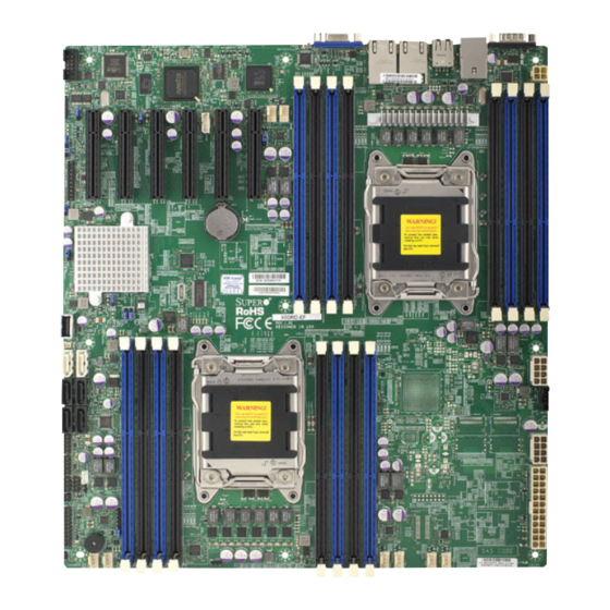
Chapter 1: Overview Chapter 1 Overview Overview Checklist Congratulations on purchasing your computer motherboard from an acknowledged leader in the industry. Supermicro boards are designed with the utmost attention to detail to provide you with the highest standards in quality and performance. Please check that the following items have all been included with your motherboard. - Page 10 X9DRD-EF Motherboard User’s Manual Motherboard Image Note: All graphics shown in this manual were based upon the latest PCB Revision available at the time of publishing of the manual. The motherboard you've received may or may not look exactly the same as the graphics...
- Page 11 USB0/1 JUIDB COM2 COM1 JPW4 CTRL IPMI_LAN FAN8 FAN7 CPU2 CPU2 JBAT1 JBT1 Battery CMOS CLEAR Intel JUSB6 X9DRD-EF BIOS Rev. 1.02 JPW3 CPU1 CPU2 JPW2 BUZZER LED2 JPW1 FAN4 FAN1 FAN3 FAN2 FAN6 JVR1 Note: For the latest CPU/Memory updates, please refer to our website at...
- Page 12 X9DRD-EF Motherboard User’s Manual X9DRD-EF Quick Reference VGA1 LAN2 LAN1 USB2/3 USB0/1 JUIDB COM2 COM1 JPW4 CTRL IPMI_LAN FAN8 FAN7 CPU2 CPU2 JBAT1 JBT1 Battery CMOS CLEAR Intel JUSB6 X9DRD-EF BIOS Rev. 1.02 JPW3 CPU1 CPU2 JPW2 BUZZER LED2 JPW1...
- Page 13 Chapter 1: Overview X9DRD-EF Jumpers Jumper Description Default Setting JBT1 Clear CMOS See Chapter 3 C1/JI SMB to PCI-E Slots Open (Disabled) JPB1 BMC Enabled Pins 1-2 (Enabled) JPG1 VGA Enabled Pins 1-2 (Enabled) JPL1 GLAN1/GLAN2 Enable Pins 1-2 (Enabled)
- Page 14 X9DRD-EF Motherboard User’s Manual (FP) USB 6 Type A USB Embedded Drive Connector Backpanel VGA Port X9DRD-EF LED Indicators Description State Status LED2 Standby PWR LED Green: On Standby PWR On LED3 Rear UID LED Blue: On Unit Identified LEDM1...
- Page 15 Chapter 1: Overview Motherboard Features • Dual Intel E5-2600 Series (Socket R-LGA 2011) pro- ® cessors; each processor supports two full-width Intel QuickPath Interconnect (QPI) links (with support of up to 25.6 GT/s per QPI link and with Data Transfer Rate of up to 8.0 GT/s per direction) •...
- Page 16 X9DRD-EF Motherboard User’s Manual Super I/O • Nuvoton 83527HG Peripheral USB Devices Devices • Four (4) USB ports on the rear I/O panel (USB 0/1, USB 2/3), • Four (4) USB connections for front access (USB 4/5, USB 8/9), •...
- Page 17 Chapter 1: Overview • Dimen- 13.00" (L) x 12.00" (W) (330.20 mm x 340.80 mm) sions Note 1: CPU Maximum Thermal Design Power (TDP) is subject to chassis and heatsink cooling restrictions. For proper thermal management, please check the chassis and heatsink specifications for proper CPU TDP sizing. Note 2: For IPMI Configuration Instructions, please refer to the Embedded IPMI Configuration User's Guide available @ http://www.supermicro.com/ support/manuals/.
- Page 18 X9DRD-EF Motherboard User’s Manual X9DRD-EF Block Diagram (AB) (AB) (CD) CPU REAR Socket 01 PROCESSOR SANDYBRIDGE CPU FRONT Socket 00 PROCESSOR SANDYBRIDGE (AB) (AB) (CD) (AB) (CD) BIOS J21 SLOT#1 SPI FLASH PCIE 3.0 x8 J22 SLOT#2 SATA Gen3 PCIE 3.0 x8...
-
Page 19: Processor And Chipset Overview
Chapter 1: Overview Processor and Chipset Overview Built upon the functionality and the capability of Intel E5-2600 Series (Socket R) processors and the C602J chipset, the X9DRD-EF motherboard provides the performance and feature sets required for dual processor-based HPC/Cluster/ Database servers. -
Page 20: Special Features
X9DRD-EF Motherboard User’s Manual Special Features Recovery from AC Power Loss The Basic I/O System (BIOS) provides a setting that determines how the system will respond when AC power is lost and then restored to the system. You can choose for the system to remain powered off (in which case you must press the power switch to turn it back on), or for it to automatically return to the power-on state. -
Page 21: Acpi Features
It is even more important for processors that have high CPU clock rates. The X9DRD-EF motherboard accommodates 24-pin ATX power supplies. Although most power supplies generally meet the specifications required by the CPU, some are inadequate. In addition, two 12V 8-pin, and the 4-pin power connections are also required to ensure adequate power supply to the system. -
Page 22: Super I/O
X9DRD-EF Motherboard User’s Manual It is strongly recommended that you use a high quality power supply that meets ATX power supply Specification 2.02 or above. It must also be SSI compliant. (For more information, please refer to the website at http://www.ssiforum.org/). Additionally, in areas where noisy power transmission is present, you may choose to install a line filter to shield the computer from noise. -
Page 23: Manageability Engine (Me)
Chapter 1: Overview Manageability Engine (ME) The Manageability Engine, which is an ARC controller embedded in the PCH, provides Server Platform Services (SPS) to your system. The services provided by SPS are different from those provided by the ME on client platforms. Overview of the Nuvoton WPCM450 Controller The Nuvoton WPCM450 Controller, a Baseboard Management Controller (BMC), supports 2D/VGA-compatible Graphic Cores with PCI interface, creating multi-media... - Page 24 X9DRD-EF Motherboard User’s Manual • Provides remote Hardware Health Monitoring via IPMI. Key features • Provides Network Management Security via remote access/console redirection. • Supports the following Management tools: IPMIView, CLI (Command Line Interface) • RMCP+ protocol supported Note 1: For more information on IPMI configuration, please refer to the IPMI User's Guide posted on our website at http://www.supermicro.com/...
-
Page 25: Chapter 2 Installation
Chapter 2: Installation Chapter 2 Installation Static-Sensitive Devices Electrostatic Discharge (ESD) can damage electronic com ponents. To avoid dam- aging your system board, it is important to handle it very carefully. The following measures are generally sufficient to protect your equipment from ESD. Precautions •... -
Page 26: Processor And Heatsink Installation
X9DRD-EF Motherboard User’s Manual Processor and Heatsink Installation Warning: When handling the processor package, avoid placing direct pressure on the label area. Notes: Always connect the power cord last, and always remove it before add- ing, removing or changing any hardware components. Make sure that you install the processor into the CPU socket before you install the CPU heatsink. - Page 27 Chapter 2: Installation 2. Press the second load lever labeled 'Close 1st' to release the load plate that covers the CPU socket from its locking position. Pull lever away from Press down on Load the socket Lever 'Close 1st' 3. With the lever labeled 'Close 1st' fully retracted, gently push down on the lever labelled 'Open 1st' to open the load plate.
- Page 28 X9DRD-EF Motherboard User’s Manual 1. Use your thumb, and index fingers to loosen the lever and open the load plate. 2. Using your thumb and index finger, hold the CPU on its edges. Align the CPU keys, which are semi-circle cutouts, against the socket keys.
- Page 29 Chapter 2: Installation 4. With the CPU inside the socket, inspect the four corners of the CPU to make sure that the CPU is properly installed. 5. Close the load plate with the CPU inside the socket. Lock the lever labelled 'Close 1st' first, then lock the lever labelled 'Open 1st' second.
-
Page 30: Installing A Passive Cpu Heatsink
X9DRD-EF Motherboard User’s Manual Installing a Passive CPU Heatsink 1. Do not apply any thermal grease to the heatsink or the CPU die -- the re- quired amount has already been applied. 2. Place the heatsink on top of the CPU so that the four mounting holes are aligned with those on the Motherboard's and the Heatsink Bracket under- neath. -
Page 31: Removing The Heatsink
Chapter 2: Installation Removing the Heatsink Warning: We do not recommend that the CPU or the heatsink be removed. However, if you do need to uninstall the heatsink, please follow the instruc- tions below to uninstall the heatsink to prevent damage done to the CPU or the CPU socket. -
Page 32: Installing And Removing The Memory Modules
X9DRD-EF Motherboard User’s Manual Installing and Removing the Memory Modules Note: Check Supermicro's website for recommended memory modules. CAUTION Exercise extreme care when installing or removing DIMM modules to prevent any possible damage. Installing & Removing DIMMs 1. Insert the desired number of DIMMs into the memory slots, starting with DIMM# A1. - Page 33 Chapter 2: Installation Memory Support for the X9DRD-EF Motherboard The X9DRD-EF motherboard supports 240-pin Registered (RDIMM)/Load Reduced (LRDIMM) ECC or Unbuffered (UDIMM) ECC/Non-ECC DDR3 800/1066/1333/1600 MHz memory modules of up to 512 GB in 4-channel 16 DIMM modules. Please refer to our website a at http://www.supermicro.com/products/motherboard.
- Page 34 X9DRD-EF Motherboard User’s Manual Populating UDIMM (ECC/Non-ECC) Memory Modules Intel E5-2600 Series Processor UDIMM Memory Support Ranks Per Memory Capacity Speed (MT/s) and Voltage Validated by Slot per Channel DIMM & Per DIMM (SPC) and DIMM Per Channel (DPC) Data Width...
- Page 35 Chapter 2: Installation Populating LRDIMM (ECC) Memory Modules Intel E5-2600 Series Processor LRDIMM Memory Support Ranks Per Memory Capacity Speed (MT/s) and Voltage Validated DIMM & Data Per DIMM by Slot per Channel (SPC) and Width DIMM Per Channel (DPC) 1 Slot Per 2 Slots Per (See the Note...
-
Page 36: Motherboard Installation
X9DRD-EF Motherboard User’s Manual Motherboard Installation All motherboards have standard mounting holes to fit different types of chassis. Make sure that the locations of all the mounting holes for both motherboard and chassis match. Although a chassis may have both plastic and metal mounting fas- teners, metal ones are highly recommended because they ground the motherboard to the chassis. -
Page 37: Installing The Motherboard
Chapter 2: Installation Installing the Motherboard 1. Install the I/O shield into the chassis. 2. Locate the mounting holes on the motherboard. 3. Locate the matching mounting holes on the chassis. Align the mounting holes on the motherboard against the mounting holes on the chassis. 4. -
Page 38: Control Panel Connectors And I/O Ports
X9DRD-EF Motherboard User’s Manual Control Panel Connectors and I/O Ports The I/O ports are color coded in conformance with the PC 99 specification. See the picture below for the colors and locations of the various I/O ports. Back Panel Connectors and I/O Ports... -
Page 39: Serial Ports
LAN1 USB2/3 USB0/1 JUIDB COM2 COM1 3. VGA JPW4 CTRL IPMI_LAN FAN8 FAN7 CPU2 CPU2 JBAT1 JBT1 Battery CMOS CLEAR Intel JUSB6 X9DRD-EF BIOS Rev. 1.02 JPW3 CPU1 CPU2 JPW2 BUZZER LED2 JPW1 FAN4 FAN3 FAN2 FAN1 FAN6 JVR1 2-15... -
Page 40: Universal Serial Bus (Usb)
X9DRD-EF Motherboard User’s Manual Universal Serial Bus (USB) FP USB (4/5, 8/9, USB 6) Backplane Pin Definitions USB (0/1, 2/3) Four Universal Serial Bus ports (USB Pin Definitions USB 4, 8, 6, USB 5, 9 0/1, USB 2/3) are located on the I/O... -
Page 41: Ethernet Ports
USB0/1 JUIDB COM2 COM1 2 GLAN2 JPW4 CTRL IPMI_LAN 3. IPMI_LAN FAN8 FAN7 CPU2 CPU2 JBAT1 JBT1 Battery CMOS CLEAR Intel JUSB6 X9DRD-EF BIOS Rev. 1.02 JPW3 CPU1 CPU2 JPW2 BUZZER LED2 JPW1 FAN4 FAN3 FAN1 FAN6 FAN2 JVR1 2-17... -
Page 42: Unit Identifier Switch/Uid Led Indicators
X9DRD-EF Motherboard User’s Manual Unit Identifier Switch/UID LED Indicators UID Switch A Unit Identifier (UID) Switch and two LED Indi- Pin# Definition cators are located on the motherboard. The UID Ground Switch is located next to the VGA port on the Ground backplane. The Rear UID LED (LED3) is located Button In next to the UID Switch. -
Page 43: Front Control Panel
USB0/1 JUIDB COM2 COM1 JPW4 CTRL IPMI_LAN FAN8 FAN7 CPU2 CPU2 JBAT1 JBT1 Battery CMOS CLEAR Intel JUSB6 BIOS X9DRD-EF Rev. 1.02 JPW3 CPU1 CPU2 JPW2 BUZZER LED2 JPW1 FAN4 FAN3 FAN2 FAN1 FAN6 JVR1 Ground 3.3 V FP PWRLED... -
Page 44: Front Control Panel Pin Definitions
X9DRD-EF Motherboard User’s Manual Front Control Panel Pin Definitions NMI Button NMI Button Pin Definitions (JF1) The non-maskable interrupt button Pin# Definition header is located on pins 19 and 20 Control of JF1. Refer to the table on the right Ground for pin definitions. Power LED... -
Page 45: Hdd Led
FAN8 FAN7 CPU2 CPU2 JBAT1 JBT1 Battery Ground CMOS CLEAR Intel FP PWRLED 3.3 V JUSB6 X9DRD-EF BIOS Rev. 1.02 HDD LED ID_UID_SW/3/3V Stby JPW3 CPU1 CPU2 NIC1 Link LED NIC1 Activity LED NIC2 Activity LED NIC2 Link LED JPW2... -
Page 46: Overheat (Oh)/Fan Fail/Pwr Fail/Uid Led
X9DRD-EF Motherboard User’s Manual Overheat (OH)/Fan Fail/PWR Fail/ OH/Fan Fail/ PWR Fail/Blue_UID UID LED LED Pin Definitions (JF1) Pin# Definition Connect an LED cable to pins 7 and Red_LED-Cathode/OH/Fan Fail/ 8 of Front Control Panel to use the Power Fail5.5V.SB Overheat/Fan Fail/Power Fail and Blue_UID LED UID LED connections. -
Page 47: Reset Button
FAN8 FAN7 CPU2 CPU2 JBAT1 JBT1 Battery CMOS CLEAR Ground Intel FP PWRLED 3.3 V JUSB6 X9DRD-EF BIOS Rev. 1.02 ID_UID_SW/3/3V Stby HDD LED JPW3 CPU1 CPU2 NIC1 Link LED NIC1 Activity LED NIC2 Activity LED NIC2 Link LED JPW2... -
Page 48: Connecting Cables
X9DRD-EF Motherboard User’s Manual Connecting Cables ATX Power 24-pin Connector Pin Definitions Power Connectors Pin# Definition Pin # Definition A 24-pin main power supply connector(JPW1), +3.3V +3.3V two 8-pin CPU power connectors (JPW2/3) and -12V +3.3V a 4-pin power connector (JPW4) are located on the motherboard. -
Page 49: Fan Headers
FAN8 FAN7 E. Fan 5 CPU2 F. Fan 6 CPU2 G. Fan 7 JBAT1 JBT1 H. Fan 8 Battery CMOS CLEAR I. Chassis Intrusion Intel JUSB6 X9DRD-EF BIOS Rev. 1.02 JPW3 CPU1 CPU2 JPW2 BUZZER LED2 JPW1 FAN4 FAN3 FAN2 FAN1... -
Page 50: Internal Speaker
X9DRD-EF Motherboard User’s Manual Internal Speaker Internal Buzzer (SP1) Pin Definition The Internal Speaker, located at SP1, Pin# Definitions can be used to provide audible indica- Pin 1 Pos. (+) Beep In tions for various beep codes. See the Pin 2 Neg. -
Page 51: Overheat Led/Fan Fail
LAN1 USB2/3 USB0/1 JUIDB COM2 COM1 B. JOH1 JPW4 CTRL IPMI_LAN FAN8 FAN7 CPU2 CPU2 JBAT1 JBT1 Battery CMOS CLEAR Intel JUSB6 X9DRD-EF BIOS Rev. 1.02 JPW3 CPU1 CPU2 JPW2 BUZZER LED2 JPW1 FAN4 FAN1 FAN3 FAN2 FAN6 JVR1 2-27... -
Page 52: Power Smb (I 2 C) Connector
X9DRD-EF Motherboard User’s Manual Power SMB (I C) Connector PWR SMB Pin Definitions Power System Management Bus (I Pin# Definition Connector (JPI C1) monitors power Clock supply, fan and system temperatures. Data See the table on the right for pin PWR Fail definitions. -
Page 53: T-Sgpio 1/2 Headers
JUIDB COM2 COM1 B. T-SGPIO2 JPW4 CTRL C. DOM PWR IPMI_LAN FAN8 FAN7 CPU2 CPU2 JBAT1 JBT1 Battery CMOS CLEAR Intel JUSB6 X9DRD-EF BIOS Rev. 1.02 JPW3 CPU1 CPU2 JPW2 BUZZER LED2 JPW1 FAN4 FAN3 FAN1 FAN6 FAN2 JVR1 2-29... -
Page 54: Standby Power Header
X9DRD-EF Motherboard User’s Manual Standby Power Header Standby PWR Pin Definitions The +5V Standby Power header is lo- Pin# Definition cated at JSTBY1 on the motherboard. +5V Standby See the table on the right for pin defini- Ground tions. (You must also have a card with... -
Page 55: Jumper Settings
LAN2 LAN1 USB2/3 USB0/1 JUIDB COM2 COM1 able JPW4 CTRL IPMI_LAN FAN8 FAN7 CPU2 CPU2 JBAT1 JBT1 Battery CMOS CLEAR Intel JUSB6 X9DRD-EF BIOS Rev. 1.02 JPW3 CPU1 CPU2 JPW2 BUZZER LED2 JPW1 FAN4 FAN3 FAN2 FAN1 FAN6 JVR1 2-31... -
Page 56: Cmos Clear
X9DRD-EF Motherboard User’s Manual CMOS Clear JBT1 is used to clear CMOS. Instead of pins, this "jumper" consists of contact pads to prevent accidental clearing of CMOS. To clear CMOS, use a metal object such as a small screwdriver to touch both pads at the same time to short the connection. -
Page 57: Vga Enable
LAN1 USB2/3 USB0/1 JUIDB COM2 COM1 BMC Enabled JPW4 CTRL IPMI_LAN FAN8 FAN7 CPU2 CPU2 JBAT1 JBT1 Battery CMOS CLEAR Intel JUSB6 X9DRD-EF BIOS Rev. 1.02 JPW3 CPU1 CPU2 JPW2 BUZZER LED2 JPW1 FAN4 FAN3 FAN1 FAN6 FAN2 JVR1 2-33... -
Page 58: I 2 C Bus To Pci-Exp. Slots
X9DRD-EF Motherboard User’s Manual C Bus to PCI-Exp. Slots C to PCI-E slots Jumper Settings Use Jumpers JI C1 and JI C2 to connect Jumper Setting Definition the System Management Bus (I C) to Closed Enabled PCI-Express slots in order to improve... -
Page 59: Onboard Led Indicators
COM1 JPW4 B. LAN2 LEDs CTRL IPMI_LAN C. IPMI LAN LEDs FAN8 FAN7 CPU2 CPU2 JBAT1 JBT1 Battery CMOS CLEAR Intel JUSB6 BIOS X9DRD-EF Rev. 1.02 JPW3 CPU1 CPU2 JPW2 BUZZER LED2 JPW1 FAN4 FAN3 FAN2 FAN1 FAN6 JVR1 2-35... -
Page 60: Onboard Power Led
X9DRD-EF Motherboard User’s Manual Onboard Power LED Onboard PWR LED Indicator LED States An Onboard Power LED is located at LED Color Definition LED2 on the motherboard. When this System Off (PWR cable not connected) LED is on, the system is on. Be sure to... -
Page 61: Unit Identification Switch/Led
A. UID LED LAN2 LAN1 USB2/3 USB0/1 JUIDB COM2 COM1 JPW4 CTRL IPMI_LAN FAN8 FAN7 CPU2 CPU2 JBAT1 JBT1 Battery CMOS CLEAR Intel JUSB6 X9DRD-EF BIOS Rev. 1.02 JPW3 CPU1 CPU2 JPW2 BUZZER LED2 JPW1 FAN4 FAN3 FAN1 FAN6 FAN2 JVR1 2-37... -
Page 62: Sata Connections
X9DRD-EF Motherboard User’s Manual SATA Connections Serial ATA Ports SATA Pin Definitions There are six Serial ATA Ports (I-SATA0-I-SATA5) Pin# Definition located on the motherboard, including two SATA Ground 3.0 ports (I-SATA 0/1) and four SATA 2.0 ports TX_P (I-SATA 2-5). These ports provide serial-link signal... -
Page 63: Chapter 3 Troubleshooting
Chapter 3: Troubleshooting Chapter 3 Troubleshooting Troubleshooting Procedures Use the following procedures to troubleshoot your system. If you have followed all of the procedures below and still need assistance, refer to the ‘Technical Support Procedures’ and/or ‘Returning Merchandise for Service’ section(s) in this chapter. Note: Always disconnect the power cord before adding, changing or installing any hardware components. - Page 64 X9DRD-EF Motherboard User’s Manual No Video 1. If the power is on, but you have no video, remove all the add-on cards and cables. 2. Use the speaker to determine if any beep codes exist. Refer to Appendix A for details on beep codes.
- Page 65 Chapter 3: Troubleshooting Memory Errors When a No-Memory Beep Code is issued by the system, check the following: 1. Make sure that the memory modules are compatible with the system and that the DIMM modules are properly and fully installed. (For memory compatibility, refer to the Memory Compatibility Chart posted on our website @ http://www.
- Page 66 X9DRD-EF Motherboard User’s Manual tings in the BIOS to make sure that the CPU and System temperatures are within the normal range. Also check the front panel Overheat LED, and make sure that the Overheat LED is not on. 5. Adequate power supply: Make sure that the power supply provides adequate power to the system.
-
Page 67: Technical Support Procedures
Chapter 3: Troubleshooting Technical Support Procedures Before contacting Technical Support, please take the following steps. Also, please note that as a motherboard manufacturer, Supermicro also sells motherboards through its channels, so it is best to first check with your distributor or reseller for troubleshooting services. -
Page 68: Battery Removal And Installation
X9DRD-EF Motherboard User’s Manual • Distributors: For immediate assistance, please have your account number ready when placing a call to our technical support department. We can be reached by e-mail at support@supermicro.com. Battery Removal and Installation Battery Removal To remove the onboard battery, follow the steps below: 1. -
Page 69: Frequently Asked Questions
Chapter 3: Troubleshooting 3. Insert the battery into the battery holder and push it down until you hear a click to ensure that the battery is securely locked. Warning: When replacing a battery, be sure to only replace it with the same type. -
Page 70: Returning Merchandise For Service
X9DRD-EF Motherboard User’s Manual Question: How do I handle the used battery? Answer: Please handle used batteries carefully. Do not damage the battery in any way; a damaged battery may release hazardous materials into the environment. Do not discard a used battery in the garbage or a public landfill. Please comply with the regulations set up by your local hazardous waste management agency to dispose of your used battery properly. -
Page 71: Chapter 4 Bios
BIOS Introduction This chapter describes the AMI BIOS Setup utility for the X9DRD-EF. It also provides the instructions on how to navigate the AMI BIOS Setup utility screens. The AMI ROM BIOS is stored in a Flash EEPROM and can be easily updated. -
Page 72: Main Setup
X9DRD-EF Motherboard User’s Manual How To Change the Configuration Data The configuration data that determines the system parameters may be changed by entering the AMI BIOS Setup utility. This Setup utility can be accessed by pressing <Delete> at the appropriate time during system boot. Note: For AMI UEFI BIOS Recovery, please refer to the UEFI BIOS Re- covery User Guide posted @http://www.supermicro.com/support/manuals/. - Page 73 Day MM/DD/YY format. The time is entered in HH:MM:SS format. (Note: The time is in the 24-hour format. For example, 5:30 P.M. appears as 17:30:00.). Supermicro X9DRD-EF Version This item displays the SMC version of the BIOS ROM used in this system.
-
Page 74: 4-3 Advanced Setup Configurations
X9DRD-EF Motherboard User’s Manual 4-3 Advanced Setup Configurations Select the Advanced tab to access the following submenu items. Boot Feature Quiet Boot This feature allows the user to select bootup screen display between POST mes- sages and the OEM logo. Select Disabled to display the POST messages. Select Enabled to display the OEM logo instead of the normal POST messages. - Page 75 Chapter 4: AMI BIOS at bootup and allow the drives that are attached to these host adaptors to function as bootable disks. If this item is set to Disabled, the ROM BIOS of the host adap- tors will not capture Interrupt 19, and the drives attached to these adaptors will not function as bootable devices.
- Page 76 X9DRD-EF Motherboard User’s Manual • Processor Cores • Intel HT (Hyper-Threading) Technology • Intel VT-x Technology • Intel SMX Technology • L1 Data Cache / L1 Code Cache • L2 Cache • L3 Cache CPU Speed This item displays the speed of the CPU installed in Socket 1/Socket 2.
- Page 77 Chapter 4: AMI BIOS Execute-Disable Bit (Available if supported by the OS & the CPU) Select Enabled to enable the Execute Disable Bit which will allow the processor to designate areas in the system memory where an application code can execute and where it cannot, thus preventing a worm or a virus from flooding illegal codes to overwhelm the processor or damage the system during an attack.
- Page 78 X9DRD-EF Motherboard User’s Manual CPU Power Management Configuration This submenu allows the user to configure the following CPU Power Manage- ment settings. Power Technology Select Energy Efficiency to support power-saving mode. Select Custom to cus- tomize system power settings. Select Disabled to disable power-saving settings.
- Page 79 Chapter 4: AMI BIOS Package C-State limit (Available when Power Technology is set to Custom) This feature allows the user to set the limit on the C-State package register. The options are C0, C2, C6, and No Limit. Energy/Performance Bias Use this feature to select an appropriate fan setting to achieve maximum system performance (with maximum cooling) or maximum energy efficiency with maxi- mum power saving).
- Page 80 X9DRD-EF Motherboard User’s Manual Chipset Configuration North Bridge This feature allows the user to configure the settings for the Intel North Bridge. Integrated IO Configuration Intel VT-d ® Select Enabled to enable Intel Virtualization Technology support for Direct I/O VT-d by reporting the I/O device assignments to the VMM (Virtual Machine Monitor) through the DMAR ACPI Tables.
- Page 81 Chapter 4: AMI BIOS CPU2 Slot3 PCI-E 3.0 x8 Link Speed/CPU2 Slot4 PCI-E 3.0 x8 Link Speed/CPU2 Slot5 PCI-E 3.0 x8 Link Speed Select GEN1 for the device installed on the slot specified to support PCI-Exp Generation 1. Select GEN2 for the device installed on the slot specified to support PCI-Exp Generation 2.
- Page 82 X9DRD-EF Motherboard User’s Manual Sparing (Available when supported by the motherboard) Memory sparing enhances system reliability, availability, and serviceability. DIMM Information CPU Socket 1 DIMM Information, CPU Socket 2 DIMM Information The status of the memory modules detected by the BIOS will be displayed as detected by the BIOS.
- Page 83 Chapter 4: AMI BIOS Demand Scrub Demand Scrubbing is a process that allows the CPU to correct correctable memory errors found on a memory module. When the CPU or I/O issues a demand-read command, and the read data from memory turns out to be a correctable error, the error is corrected and sent to the requestor (the original source).
- Page 84 X9DRD-EF Motherboard User’s Manual Legacy USB Support (Available when USB Functions is not Disabled) Select Enabled to support legacy USB devices. Select Auto to disable legacy sup- port if USB devices are not present. Select Disabled to have USB devices available for EFI (Extensive Firmware Interface) applications only.
- Page 85 Chapter 4: AMI BIOS AHCI Mode The following items are displayed when the AHCI Mode is selected. Aggressive Link Power Management When Enabled, the SATA AHCI controller manages the power usage of the SATA link. The controller will put the link in a low power mode during extended periods of I/O inactivity, and will return the link to an active state when I/O activity resumes.
- Page 86 X9DRD-EF Motherboard User’s Manual PERR# Generation Select Enabled to allow a PCI device to generate a PERR number for a PCI Bus Signal Error Event. The options are Enabled and Disabled. SERR# Generation Select Enabled to allow a PCI device to generate an SERR number for a PCI Bus Signal Error Event.
- Page 87 Chapter 4: AMI BIOS VGA Priority This feature allows the user to select the graphics adapter to be used as the primary boot device. The options are Onboard, and Offboard. Network Stack Select Enabled enable PXE (Preboot Execution Environment) or UEFI (Unified Extensible Firmware Interface) for network stack support.
- Page 88 X9DRD-EF Motherboard User’s Manual Change Settings This option specifies the base I/O port address and the Interrupt Request address of Serial Port 2. Select Disabled to prevent the serial port from accessing any system resources. When this option is set to Disabled, the serial port becomes unavailable.
- Page 89 Chapter 4: AMI BIOS Bits Per second Use this feature to set the transmission speed for a serial port used in Console Redirection. Make sure that the same speed is used in the host computer and the client computer. A lower transmission speed may be required for long and busy lines.
- Page 90 X9DRD-EF Motherboard User’s Manual Legacy OS Redirection Resolution Use this feature to select the number of rows and columns used in Console Redirection for legacy OS support. The options are 80x24 and 80x25. Putty KeyPad This feature selects Function Keys and KeyPad settings for Putty, which is a terminal emulator designed for the Windows OS.
- Page 91 Chapter 4: AMI BIOS Bits Per Second This item sets the transmission speed for a serial port used in Console Redirec- tion. Make sure that the same speed is used in the host computer and the client computer. A lower transmission speed may be required for long and busy lines. The options are 9600, 19200, 57600, and 115200 (bits per second).
- Page 92 X9DRD-EF Motherboard User’s Manual Trusted Computing (Available when a TPM device is detected by the BIOS) Configuration TPM Support Select Enabled on this item and enable the TPM jumper on the motherboard to enable TPM support to improve data integrity and network security. The options are Enabled and Disabled.
- Page 93 Chapter 4: AMI BIOS Chipset: TXT (Trusted Execution Technology) Feature Intel TXT (LT-SX) Configuration This feature displays the following TXT configuration setting. TXT (LT-SX) Support: This item indicates if the Intel TXT support is enabled or disabled. The default setting is Disabled. Intel TXT (LT-SX) Dependencies This feature displays the features that need to be enabled for the Intel Trusted Execution Technology to work properly in the system.
- Page 94 X9DRD-EF Motherboard User’s Manual Intel Ethernet Controller I350 Gigabit Network Connection: These items display ® the following information on the Intel I350 Gigabit network connections. NIC Configuration Link Speed Use this feature to change the link speed and duplex for the current port. The op- tions are AutoNeg, 10Mbps Half, 10Mbps Full, 100Mbps Half, and 100Mbps full.
-
Page 95: Event Logs
Chapter 4: AMI BIOS Event Logs Select the Event Logs tab to access the following submenu items. Change SMBIOS Event Log Settings This feature allows the user to configure SMBIOS Event settings. Enabling/Disabling Options SMBIOS Event Log Select Enabled to enable SMBIOS (System Management BIOS) Event Logging during system boot. - Page 96 X9DRD-EF Motherboard User’s Manual Erasing Settings Erase Event Log Select Enabled to erase the SMBIOS (System Management BIOS) Event Log, which is completed before a event logging is initialized upon system reboot. The options are No, Yes, Next reset, and Yes, Every reset.
-
Page 97: Ipmi
Chapter 4: AMI BIOS IPMI Select the IPMI (Intelligent Platform Management Interface) tab to access the fol- lowing submenu items. IPMI Firmware Revision This item indicates the IPMI firmware revision used in your system. IPMI Status This item indicates the status of the IPMI firmware installed in your system. System Event Log ... - Page 98 X9DRD-EF Motherboard User’s Manual When SEL is Full This feature allows the user to decide what the BIOS should do when the system event log is full. Select Erase Immediately to erase all events in the log when the system event log is full. The options are Do Nothing and Erase Immediately.
-
Page 99: Boot
Chapter 4: AMI BIOS Gateway IP Address This item displays the Gateway IP address for this computer. This should be in decimal and in dotted quad form (i.e., 192.168.10.253). Boot This submenu allows the user to configure the following boot settings for the system. -
Page 100: Security
X9DRD-EF Motherboard User’s Manual Security This menu allows the user to configure the following security settings for the system. Password Check Use this feature to determine when a password entry is required. Select Setup to require the password only when entering setup. Select Always to require the pass- word when entering setup and on each boot. -
Page 101: Save & Exit
Chapter 4: AMI BIOS Save & Exit This submenu allows the user to configure the Save and Exit settings for the system. Discard Changes and Exit Select this option to quit the BIOS Setup without making any permanent changes to the system configuration, and reboot the computer. Select Discard Changes and Exit, and press <Enter>. - Page 102 X9DRD-EF Motherboard User’s Manual Discard Changes Select this feature and press <Enter> to discard all the changes and return to the BIOS setup. When the dialog box appears, asking you if you want to load previ- ous values, select Yes to load the values previous saved, or select No to keep the changes you've made so far.
-
Page 103: Appendix A Bios Error Beep Codes
Appendix A: BIOS POST Error Codes Appendix A BIOS Error Beep Codes During the POST (Power-On Self-Test) routines, which are performed at each system boot, errors may occur. Non-fatal errors are those which, in most cases, allow the system to continue to boot. - Page 104 X9DRD-EF Motherboard User’s Manual Notes...
-
Page 105: Appendix B Software Installation Instructions
Appendix B: Software Installation Instructions Appendix B Software Installation Instructions B-1 Installing Software Programs After you've installed the operating system, a screen as shown below will appear. You are ready to install software programs and drivers that have not yet been in- stalled. -
Page 106: Configuring Superdoctor Iii (For Windows Os Only
X9DRD-EF Motherboard User’s Manual B-2 Configuring SuperDoctor III (For Windows OS Only) The SuperDoctor III program is a Web-based management tool that supports remote management capability. It includes Remote and Local Management tools. The local management is called the SD III Client. The SuperDoctor III program included on the CDROM that came with your motherboard allows you to monitor the environment and operations of your system. - Page 107 Appendix B: Software Installation Instructions SuperDoctor III Interface Display Screen-II (Remote Control) Note: SD III software and the user's guide can be downloaded from our website at: http://www.supermicro.com/products/accessories/software/ SuperDoctorIII.cfm. For Linux, we will still recommend that you use SuperDoctor II.
- Page 108 X9DRD-EF Motherboard User’s Manual Notes...
- Page 109 (Disclaimer Continued) The products sold by Supermicro are not intended for and will not be used in life support systems, medical equipment, nuclear facilities or systems, aircraft, aircraft devices, aircraft/emergency communication devices or other critical systems whose failure to perform be reasonably expected to result in significant injury or loss of life or catastrophic property damage.
Need help?
Do you have a question about the X9DRD-EF and is the answer not in the manual?
Questions and answers