Table of Contents
Advertisement
Quick Links
Advertisement
Table of Contents

Subscribe to Our Youtube Channel
Related Manuals for Supero X9DR7-LN4F


Summary of Contents for Supero X9DR7-LN4F
- Page 1 X9DR7-LN4F X9DR7-LN4F-JBOD X9DRE-LN4F USER’S MANUAL Revision 1.1...
- Page 2 This product, including software and docu- mentation, is the property of Supermicro and/or its licensors, and is supplied only under a license. Any use or reproduction of this product is not allowed, except as expressly permitted by the terms of said license.
-
Page 3: About This Motherboard
Digital Media Interface (DMI), PCI-E Gen. 3.0 and up to 1866 MHz DDR3 memory. This motherboard is ideal for high-end server platforms. Please refer to our Website (http://www.supermicro.com) for CPU and memory support updates. Manual Organization Chapter 1 describes the features, specifications and performance of the mother- board, and provides detailed information about the Intel PCH C602 chipset. -
Page 4: Conventions Used In The Manual
X9DR7-LN4F/X9DR7-LN4F-JBOD/X9DRE-LN4F Motherboard User’s Manual Conventions Used in the Manual Pay special attention to the following symbols for proper system installation and to prevent damage to the system or injury to yourself: Warning: Important information given to ensure proper system installation or to prevent... -
Page 5: Contacting Supermicro
Super Micro Computer, Inc. 980 Rock Ave. San Jose, CA 95131 U.S.A. Tel: +1 (408) 503-8000 Fax: +1 (408) 503-8008 Email: marketing@supermicro.com (General Information) support@supermicro.com (Technical Support) Web Site: www.supermicro.com Europe Address: Super Micro Computer B.V. Het Sterrenbeeld 28, 5215 ML... -
Page 6: Table Of Contents
X9DR7-LN4F/X9DR7-LN4F-JBOD/X9DRE-LN4F Motherboard User’s Manual Table of Contents Preface Chapter 1 Overview Overview ......................1-1 Processor and Chipset Overview..............1-11 Special Features ................... 1-12 PC Health Monitoring ..................1-12 ACPI Features ....................1-13 Power Supply ....................1-13 Advanced Power Management ..............1-14 Intel Intelligent Power Node Manager (IPNM) .......... - Page 7 Table of Contents Universal Serial Bus (USB) ..............2-20 Ethernet Ports ..................2-21 Front Control Panel ..................2-22 Front Control Panel Pin Definitions............... 2-23 NMI Button ....................2-23 Power LED ....................2-23 HDD LED ....................2-24 NIC1/NIC2 LED Indicators ............... 2-24 Overheat (OH)/Fan Fail LED..............
- Page 8 Onboard Power LED ................2-40 BMC Heartbeat LED ................2-40 2-10 Serial ATA Connections ................. 2-41 Serial ATA Ports..................2-41 SAS Ports (X9DR7-LN4F/X9DR7-LN4F-JBOD Only) ......2-41 Chapter 3 Troubleshooting Troubleshooting Procedures ................3-1 Technical Support Procedures ................ 3-5 Battery Removal and Installation ..............3-6 Frequently Asked Questions ................
-
Page 9: Chapter 1 Overview
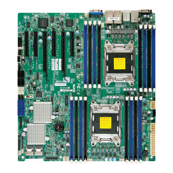
Checklist Congratulations on purchasing your computer motherboard from an acknowledged leader in the industry. Supermicro boards are designed with the utmost attention to detail to provide you with the highest standards in quality and performance. Please check that the following items have all been included with your motherboard. - Page 10 X9DR7-LN4F/X9DR7-LN4F-JBOD/X9DRE-LN4F Motherboard User’s Manual Motherboard Image Note: All graphics shown in this manual were based upon the latest PCB Revision available at the time of publishing of the manual. The motherboard you've received may or may not look exactly the same as the graphics...
-
Page 11: Motherboard Layout
Note 1: For the latest CPU/Memory updates, please refer to our Website at http://www.supermicro.com/products/motherboard/ for details. Note 2: Changing BMC log-in information is recommended during initial system power-on. The default username is ADMIN and password is ADMIN. For BMC best practices, please refer to: http://www.supermicro. com/products/nfo/files/IPMI/Best_Practices_BMC_Security.pdf... - Page 12 X9DR7-LN4F/X9DR7-LN4F-JBOD/X9DRE-LN4F Motherboard User’s Manual X9DR7-LN4F/X9DR7-LN4F-JBOD/X9DRE-LN4F Quick Reference COM1 USB2&3 USB0&1 JPB1 CTRL CTRL KB/Mouse FAN5 IPMI_LAN LAN2/4 LAN1/3 JPL1 CPU2 CLOSE 1st JIPMB1 JPME1 SCU-SGPIO1 OPEN 1st X9DR7/E-LN4F Rev. 1.00 T-SGPIO1 BIOS CPU1 JBT1 CLOSE 1st Battery JPW2 JBAT1 CTRL...
- Page 13 Chapter 1: Overview X9DR7-LN4F/X9DR7-LN4F-JBOD/X9DRE-LN4F Jumpers Jumper Description Default Setting C1/JI SMB to PCI-E Slots Pins 2-3 (Disabled) JBT1 Clear CMOS See Chapter 2 JPB1 BMC Enabled Pins 1-2 (Enabled) JPG1 VGA Enabled Pins 1-2 (Enabled) JPL1 GLAN1-GLAN4 Enable Pins 1-2 (Enabled)
- Page 14 X9DR7-LN4F/X9DR7-LN4F-JBOD/X9DRE-LN4F Motherboard User’s Manual (L)SAS SAS Connections 0-3, 4-7 supported by LSI SAS Control- ler (for X9DR7-LN4F/-JBOD) Onboard Buzzer (Internal Speaker) SCU-SGPIO 1 SCU-SGPIO (Serial_Link General Purpose I/O) Header 1 to support S-SATA 0-3 from Intel SCU T-SGPIO 1/2 T-SGPIO (Serial_Link General Purpose I/O) Headers 1/2...
-
Page 15: Motherboard Features
(I-SATA 2-5) Ports, Four (4) SATA 2.0 from Intel SCU (S-SATA0-3) Eight (8) SAS Connections sup- ported by the LSI 2308 SAS controller (for X9DR7-LN4F) Eight (8) SAS 2.0 (IT Mode) Connections supported by the LSI 2308 SAS 2.0 controller (for X9DR7-LN4F-JBOD) •... - Page 16 X9DR7-LN4F/X9DR7-LN4F-JBOD/X9DRE-LN4F Motherboard User’s Manual • RAID (SAS) RAID 0, 1,10 (LSI-SAS Con- troller) Integrated IPMI 2.0 • IPMI 2.0 supported by the WPCM450R BMC Serial (COM) Port • Two (2) Fast UART 16550 Connection: 9-pin RS- 232 port Super I/O •...
- Page 17 Note 2: For IPMI Configuration Instructions, please refer to the Embedded IPMI Configuration User's Guide available @ http://www.supermicro.com/ support/manuals/. Note 3: Changing BMC log-in information is recommended during initial system power-on. The default username is ADMIN and password is ADMIN. For BMC best practices, please refer to: http://www.supermicro.com/products/ nfo/files/IPMI/Best_Practices_BMC_Security.pdf...
-
Page 18: System Block Diagram
X9DR7-LN4F/X9DR7-LN4F-JBOD/X9DRE-LN4F Motherboard User’s Manual #H-2 #H-1 #G-2 #G-1 #D-2 #F-2 #D-1 #F-1 #C-2 #E-2 #C-1 E5-2600(v2) (CPU1) E5-2600(v2) (CPU2) #E-1 #B-2 DDR3 DDR3 #B-1 #A-2 #A-1 #2A #1 #3C DMI2 DMI2 PCI-E X16 G3 PCI-E X8 G3 PCI-E X16 G3... -
Page 19: Processor And Chipset Overview
Built upon the functionality and the capability of Intel E5-2600(v2) Series Proces- ® sor (Socket R LGA 2011) and the PCH C602 chipset, the X9DR7-LN4F/-JBOD/ X9DRE-LN4F motherboard provides the performance and feature sets required for dual_processor-based high-end servers. (See note below for processor support.) -
Page 20: Special Features
X9DR7-LN4F/X9DR7-LN4F-JBOD/X9DRE-LN4F Motherboard User’s Manual Special Features Recovery from AC Power Loss The Basic I/O System (BIOS) provides a setting that determines how the system will respond when AC power is lost and then restored to the system. You can choose for the system to remain powered off (in which case you must press the power switch to turn it back on), or for it to automatically return to the power-on state. -
Page 21: Acpi Features
It is even more important for processors that have high CPU clock rates. The X9DR7-LN4F-JBOD/X9DRE-LN4F motherboard accommodates 24-pin ATX power supplies. Although most power supplies generally meet the specifications required by the CPU, some are inadequate. In addition, two 12V 8-pin power con- nections are also required to ensure adequate power supply to the system. -
Page 22: Advanced Power Management
X9DR7-LN4F/X9DR7-LN4F-JBOD/X9DRE-LN4F Motherboard User’s Manual areas where noisy power transmission is present, you may choose to install a line filter to shield the computer from noise. It is recommended that you also install a power surge protector to help avoid problems caused by power surges. -
Page 23: Other Features Supported By The Wpcm Bmc Controller
Chapter 1: Overview control Super IO functions. The WPCM450R Controller is connected to the network via an external Ethernet PHY module or shared NCSI connections. In addition, two high-speed, 16550 compatible serial communication ports (UARTs) are also supported by the WPCM450R controller. Each UART includes a 16-byte send/receive FIFO, a programmable baud rate generator, complete modem control capability, and a processor interrupt system. - Page 24 • RMCP+ protocol supported Note 1: For more information on IPMI configuration, please refer to the IPMI User's Guide posted on our website at http://www.supermicro.com/ support/manuals/. Note 2: The term "IPMI controller" and the term "BMC controller" can be used interchangeably in this section.
-
Page 25: Chapter 2 Installation
The following statements are industry-standard warnings provided to warn the user of situations when potential bodily injury may occur. Should you have questions or experience difficulty, contact Supermicro's Technical Support department for assis- tance. Only certified technicians should attempt to install or configure components. - Page 26 X9DR7-LN4F/X9DR7-LN4F-JBOD/X9DRE-LN4F Motherboard User’s Manual Attention Danger d'explosion si la pile n'est pas remplacée correctement. Ne la remplacer que par une pile de type semblable ou équivalent, recommandée par le fabricant. Jeter les piles usagées conformément aux instructions du fabricant. كيلعف ةحيحص ريغ ةقيرطب ةيراطبلا لادبتسا ةلاح يف راجفنا نم رطخ كانه...
-
Page 27: Product Disposal
Chapter 2: Installation Product Disposal Warning! Ultimate disposal of this product should be handled according to all national laws and regulations. Warnung Die Entsorgung dieses Produkts sollte gemäß allen Bestimmungen und Gesetzen des Landes erfolgen. ¡Advertencia! Al deshacerse por completo de este producto debe seguir todas las leyes y regla- mentos nacionales. -
Page 28: Static-Sensitive Devices
X9DR7-LN4F/X9DR7-LN4F-JBOD/X9DRE-LN4F Motherboard User’s Manual Static-Sensitive Devices Electrostatic Discharge (ESD) can damage electronic com ponents. To avoid dam- aging your system board, it is important to handle it very carefully. The following measures are generally sufficient to protect your equipment from ESD. -
Page 29: Processor And Heatsink Installation
Chapter 2: Installation Processor and Heatsink Installation Warning: When handling the processor package, avoid placing direct pressure on the label area. Refer to our website for CPU updates/support. Notes: • Always connect the power cord last, and always remove it before adding, removing or changing any hardware components. - Page 30 X9DR7-LN4F/X9DR7-LN4F-JBOD/X9DRE-LN4F Motherboard User’s Manual 2. Press the second load lever labeled 'Close 1st' to release the load plate that covers the CPU socket from its locking position. Pull lever away from Press down on 0the Load the socket Lever labeled 'Close 1st' 3.
- Page 31 Chapter 2: Installation 1. Use your index finger and your thumb to loosen the lever and open the load plate. Align Pin1 of the CPU with Pin 1 of the CPU Socket. 2. Once they are aligned, carefully lower the CPU straight down into the socket. (Do not drop the CPU on the socket.
- Page 32 X9DR7-LN4F/X9DR7-LN4F-JBOD/X9DRE-LN4F Motherboard User’s Manual 4. Close the load plate with the CPU inside the socket. Lock the lever labeled 'Close 1st' first, then lock the lever labeled 'Open 1st' second. Use your thumb to gently push the load levers down to the lever locks.
-
Page 33: Installing A Passive Cpu Heatsink
Chapter 2: Installation Installing a Passive CPU Heatsink 1. Do not apply any thermal grease to the heatsink or the CPU die -- the re- quired amount has already been applied. 2. Place the heatsink on top of the CPU so that the four mounting holes are aligned with those on the Motherboard's and the Heatsink Bracket under- neath. -
Page 34: Removing The Heatsink
X9DR7-LN4F/X9DR7-LN4F-JBOD/X9DRE-LN4F Motherboard User’s Manual Removing the Heatsink Warning: We do not recommend that the CPU or the heatsink be removed. However, if you do need to uninstall the heatsink, please follow the instructions below to uninstall the heatsink to prevent damage done to the CPU or the CPU socket. -
Page 35: Installing And Removing The Memory Modules
Chapter 2: Installation Installing and Removing the Memory Modules Note: Check Supermicro's Website for recommended memory modules. CAUTION Exercise extreme care when installing or removing DIMM modules to prevent any possible damage. Installing & Removing DIMMs 1. Insert the desired number of DIMMs into the memory slots, starting with P1-DIMMA1. - Page 36 GB of Registered (RDIMM) or 128 GB of Unbuffered (UDIMM) ECC/Non-ECC DDR3 800/1066/1333/1600/1866 MHz 240-pin 4-channel memory in 16 DIMM slots. For the latest memory updates, please refer to our website at http://www.supermicro. com/products/motherboard. Processor & Memory Module Population Configuration For memory to work properly, follow the tables below for memory installation.
- Page 37 1600 1866 1866 Note: For detailed information on memory support and updates, please refer to the SMC Recommended Memory List posted on our website at http://www.supermicro.com/support/resources/mem.cfm. Populating RDIMM (ECC) Memory Modules Intel E5-2600(v2) Series Processor RDIMM Memory Support Ranks Memory Capacity...
- Page 38 1333, 1333 1333 Note: For detailed information on memory support and updates, please refer to the SMC Recommended Memory List posted on our website at http://www.supermicro.com/support/resources/mem.cfm. Populating RDIMM (ECC) Memory Modules Intel E5-2600 Series Processor RDIMM Memory Support Ranks Memory Capacity...
- Page 39 1066 1066 (QDP) Note: For detailed information on memory support and updates, please refer to the SMC Recommended Memory List posted on our website at http://www.supermicro.com/support/resources/mem.cfm. Intel E5-2600 Series Processor LRDIMM Memory Support Ranks Memory Speed (MT/s) and Voltage Validated by Slot per Channel (SPC) and DIMM Per...
-
Page 40: Motherboard Installation
X9DR7-LN4F/X9DR7-LN4F-JBOD/X9DRE-LN4F Motherboard User’s Manual Motherboard Installation All motherboards have standard mounting holes to fit different types of chassis. Make sure that the locations of all the mounting holes for both motherboard and chassis match. Although a chassis may have both plastic and metal mounting fas- teners, metal ones are highly recommended because they ground the motherboard to the chassis. -
Page 41: Installing The Motherboard
Chapter 2: Installation Installing the Motherboard 1. Install the I/O shield into the chassis. 2. Locate the mounting holes on the motherboard. 3. Locate the matching mounting holes on the chassis. Align the mounting holes on the motherboard against the mounting holes on the chassis. 4. -
Page 42: Control Panel Connectors And I/O Ports
X9DR7-LN4F/X9DR7-LN4F-JBOD/X9DRE-LN4F Motherboard User’s Manual Control Panel Connectors and I/O Ports The I/O ports are color coded in conformance with the PC 99 specification. See the picture below for the colors and locations of the various I/O ports. Back Panel Connectors and I/O Ports USB2&3... -
Page 43: Serial Ports
Chapter 2: Installation Serial Ports Serial (COM) Ports Pin Definitions Two COM connections (COM1 & Pin # Definition Pin # Definition COM2) are located on the mother- board. COM1 is located on the Back- plane I/O panel. COM2, located close to PCI-E Slot1, provides front access support. -
Page 44: Universal Serial Bus (Usb)
X9DR7-LN4F/X9DR7-LN4F-JBOD/X9DRE-LN4F Motherboard User’s Manual Universal Serial Bus (USB) FP USB (4/5, USB 9) Pin Definitions Four Universal Serial Bus ports (USB USB 4, 6 USB 5 0/1, USB 2/3) are located on the I/O Pin # Definition Pin # Definition back panel. In addition, two USB... -
Page 45: Ethernet Ports
Chapter 2: Installation Ethernet Ports LAN Ports Pin Definition Four Gigabit Ethernet ports (LAN1/ Pin# Definition LAN3, LAN2/LAN4) are located on the P2V5SB SGND I/O backplane on the motherboard. In TD0+ Act LED addition, an IPMI_Dedicated LAN is TD0- P3V3SB located above USB 0/1 ports on the TD1+ Link 100 LED (Yel- backplane to provide KVM support... -
Page 46: Front Control Panel
These connectors are designed specifically for use with Supermicro's server chassis. See the figure below for the descriptions of the various control panel buttons and LED indicators. Refer to the following section for descriptions and pin definitions. -
Page 47: Front Control Panel Pin Definitions
Chapter 2: Installation Front Control Panel Pin Definitions NMI Button NMI Button Pin Definitions (JF1) The non-maskable interrupt button Pin# Definition header is located on pins 19 and 20 Control of JF1. Refer to the table on the right Ground for pin definitions. Power LED Power LED Pin Definitions (JF1) The Power LED connection is located Pin#... -
Page 48: Hdd Led
X9DR7-LN4F/X9DR7-LN4F-JBOD/X9DRE-LN4F Motherboard User’s Manual HDD LED HDD LED Pin Definitions (JF1) The HDD LED connection is located Pin# Definition on pins 13 and 14 of JF1. Attach a 3.3V Standby cable here to indicate HDD activ- HD Active ity. See the table on the right for pin definitions. -
Page 49: Overheat (Oh)/Fan Fail Led
Chapter 2: Installation Overheat (OH)/Fan Fail LED OH/Fan Fail LED Pin Definitions (JF1) Connect an LED cable to pins 7 and Pin# Definition 8 of Front Control Panel to use the Overheat/Fan Fail LED connections. OH/Fan Fail LED The LED on pin 8 provides warnings of overheat or fan failure. -
Page 50: Reset Button
X9DR7-LN4F/X9DR7-LN4F-JBOD/X9DRE-LN4F Motherboard User’s Manual Reset Button Reset Button Pin Definitions (JF1) The Reset Button connection is located Pin# Definition on pins 3 and 4 of JF1. Attach it to a Reset hardware reset switch on the computer Ground case. Refer to the table on the right for pin definitions. -
Page 51: Connecting Cables
Chapter 2: Installation Connecting Cables ATX Power 24-pin Connector Pin Definitions Pin# Definition Pin # Definition Power Connectors +3.3V +3.3V -12V +3.3V A 24-pin main power supply connector(J22) and two 8-pin CPU PWR connectors PS_ON (JPWR1/2,) are located on the mother- board. -
Page 52: Fan Headers
X9DR7-LN4F/X9DR7-LN4F-JBOD/X9DRE-LN4F Motherboard User’s Manual Fan Headers Fan Header Pin Definitions This motherboard has eight system/CPU Pin# Definition fan headers (Fan 1-Fan 6, Fan A, Fan B) Ground on the motherboard. All these 4-pin fans +12V headers are backward compatible with Tachometer the traditional 3-pin fans. -
Page 53: Internal Speaker
Chapter 2: Installation Internal Speaker Internal Buzzer (SP1) Pin Definition The Internal Speaker, located at SP1, Pin# Definitions can be used to provide audible indica- Pin 1 Pos. (+) Beep In tions for various beep codes. See the Pin 2 Neg. (-) Alarm table on the right for pin definitions. -
Page 54: Tpm Header/Port 80
X9DR7-LN4F/X9DR7-LN4F-JBOD/X9DRE-LN4F Motherboard User’s Manual TPM Header/Port 80 TPM/Port 80 Header Pin Definitions A Trusted Platform Module/Port 80 Pin # Definition Pin # Definition header is located at JTPM1 to provide LCLK TPM support and Port 80 connection. LFRAME# <(KEY)> Use this header to enhance system... -
Page 55: Power Smb (I 2 C) Connector
Chapter 2: Installation Power SMB (I C) Connector PWR SMB Pin Definitions Power System Management Bus (I Pin# Definition Connector (JPI C1) monitors power Clock supply, fan and system temperatures. Data See the table on the right for pin PWR Fail definitions. -
Page 56: T-Sgpio 1/2 And Scu-Sgpio 1 Headers
X9DR7-LN4F/X9DR7-LN4F-JBOD/X9DRE-LN4F Motherboard User’s Manual T-SGPIO 1/2 and SCU-SGPIO 1 T-SGPIO/SCU-SGPIO Headers Pin Definitions Pin# Definition Definition Two SGPIO (Serial-Link General Pur- pose Input/Output) headers, located at T-SGPIO 1/2, support I-SATA 0-5. Ground Data Additionally, SCU-SGPIO 1 provides Load Ground support to S-SATA 0-3 from Intel Clock SCU chip. -
Page 57: Standby Power Connector
Chapter 2: Installation Standby Power Connector Standby PWR Pin Definitions A header for the standby power con- Pin# Definition nector is located at JSTBY1. Connect an appropriate cable here to provide Ground power support for your PCI-Exp. Ground devices. LAN3/LAN4 LED Connection LAN3/LAN4 LED Pin Definitions A 4-pin header (JF2), located next to... -
Page 58: Jumper Settings
X9DR7-LN4F/X9DR7-LN4F-JBOD/X9DRE-LN4F Motherboard User’s Manual Jumper Settings Explanation of Jumpers Connector Pins To modify the operation of the mother- board, jumpers can be used to choose between optional settings. Jumpers create Jumper shorts between two pins to change the function of the connector. Pin 1 is identified with a square solder pad on the printed circuit board. -
Page 59: Cmos Clear
Chapter 2: Installation CMOS Clear JBT1 is used to clear CMOS. Instead of pins, this "jumper" consists of contact pads to prevent accidental clearing of CMOS. To clear CMOS, use a metal object such as a small screwdriver to touch both pads at the same time to short the connection. Always remove the AC power cord from the system before clearing CMOS. -
Page 60: Vga Enable
X9DR7-LN4F/X9DR7-LN4F-JBOD/X9DRE-LN4F Motherboard User’s Manual VGA Enable VGA Enable Jumper Settings Jumper JPG1 allows the user to enable Jumper Setting Definition the onboard VGA connector. The default Enabled (Default) setting is 1-2 to enable the connection. Disabled See the table on the right for jumper settings. -
Page 61: Management Engine (Me) Recovery
Chapter 2: Installation Management Engine (ME) Recovery ME Recovery Jumper Settings Use Jumper JPME1 to select ME Firm- Jumper Setting Definition ware Recovery mode, which will limit Normal (Default) resource allocation for essential system ME Recovery operation only in order to maintain nor- mal power operation and management. -
Page 62: I 2 C Bus To Pci-Exp. Slots
X9DR7-LN4F/X9DR7-LN4F-JBOD/X9DRE-LN4F Motherboard User’s Manual C Bus to PCI-Exp. Slots C to PCI-E slots Jumper Settings Use Jumpers JI C1 and JI C2 to connect Jumper Setting Definition the System Management Bus (I C) to Pins 1-2 Enabled (Default) PCI-Express slots to improve PCI slot... -
Page 63: Onboard Led Indicators
Chapter 2: Installation Onboard LED Indicators GLAN LEDs Link Speed LED Activity LED There are four GLAN ports on the moth- erboard. Each Ethernet LAN port has Rear View (when facing the two LEDs. The Yellow LED on the right rear side of the chassis) indicates connection and activity. -
Page 64: Onboard Power Led
X9DR7-LN4F/X9DR7-LN4F-JBOD/X9DRE-LN4F Motherboard User’s Manual Onboard Power LED Onboard PWR LED Indicator (LE1) LED Settings An Onboard Power LED is located at LE1 Color/State Definition on the motherboard. When this LED is on, System Off (PWR cable not the system is on. Be sure to turn off the... -
Page 65: 2-10 Serial Ata Connections
SAS Ports (X9DR7-LN4F/X9DR7-LN4F-JBOD Only) Eight SAS Ports (SCU 0-3, 4-7) are located on the X9DR7-LN4F/-JBOD to provide Serial _Attached SCSI connections. These ports are supported by the LSI 2308 SAS controller. See the table on the right for pin definitions. - Page 66 X9DR7-LN4F/X9DR7-LN4F-JBOD/X9DRE-LN4F Motherboard User’s Manual Notes 2-42...
-
Page 67: Chapter 3 Troubleshooting
Chapter 3: Troubleshooting Chapter 3 Troubleshooting Troubleshooting Procedures Use the following procedures to troubleshoot your system. If you have followed all of the procedures below and still need assistance, refer to the ‘Technical Support Procedures’ and/or ‘Returning Merchandise for Service’ section(s) in this chapter. Note: Always disconnect the power cord before adding, changing or installing any hardware components. -
Page 68: System Boot Failure
X9DR7-LN4F/X9DR7-LN4F-JBOD/X9DRE-LN4F Motherboard User’s Manual No Video 1. If the power is on, but you have no video, remove all the add-on cards and cables. 2. Use the speaker to determine if any beep codes exist. Refer to Appendix A for details on beep codes. -
Page 69: Memory Errors
2. Memory support: Make sure that the memory modules are supported by test- ing the modules using memtest86 or a similar utility. Note: Refer to the product page on our website http://www.supermicro. com for memory and CPU support and updates. - Page 70 X9DR7-LN4F/X9DR7-LN4F-JBOD/X9DRE-LN4F Motherboard User’s Manual 4. System cooling: Check system cooling to make sure that all heatsink fans, and CPU/system fans, etc., work properly. Check Hardware Monitoring set- tings in the BIOS to make sure that the CPU and System temperatures are within the normal range.
-
Page 71: Technical Support Procedures
Technical Support Procedures Before contacting Technical Support, please take the following steps. Also, please note that as a motherboard manufacturer, Supermicro also sells motherboards through its channels, so it is best to first check with your distributor or reseller for troubleshooting services. -
Page 72: Battery Removal And Installation
X9DR7-LN4F/X9DR7-LN4F-JBOD/X9DRE-LN4F Motherboard User’s Manual Battery Removal and Installation Battery Removal To remove the onboard battery, follow the steps below: 1. Power off your system and unplug your power cable. 2. Locate the onboard battery as shown below. 3. Using a tool such as a pen or a small screwdriver, push the battery lock out- wards to unlock it. -
Page 73: Frequently Asked Questions
Note : The SPI BIOS chip used on this motherboard cannot be removed. Send your motherboard back to our RMA Department at Supermicro for repair. For BIOS Recovery instructions, please refer to the AMI BIOS Recovery Instructions posted at http://www.supermicro.com. -
Page 74: Returning Merchandise For Service
X9DR7-LN4F/X9DR7-LN4F-JBOD/X9DRE-LN4F Motherboard User’s Manual Returning Merchandise for Service A receipt or copy of your invoice marked with the date of purchase is required before any warranty service will be rendered. You can obtain service by calling your ven- dor for a Returned Merchandise Authorization (RMA) number. When returning the... -
Page 75: Chapter 4 Bios
Chapter 4 BIOS Introduction This chapter describes the AMI BIOS Setup utility for the X9DR7-LN4F/X9DR7- LN4F-JBOD/X9DRE-LN4F. It also provides the instructions on how to navigate the AMI BIOS Setup utility screens. The AMI ROM BIOS is stored in a Flash EEPROM and can be easily updated. -
Page 76: Main Setup
X9DR7-LN4F/X9DR7-LN4F-JBOD/X9DRE-LN4F Motherboard User’s Manual How To Change the Configuration Data The configuration data that determines the system parameters may be changed by entering the AMI BIOS Setup utility. This Setup utility can be accessed by pressing <Delete> at the appropriate time during system boot. Note: For AMI UEFI BIOS Recovery, please refer to the UEFI BIOS Re- covery User Guide posted @http://www.supermicro.com/support/manuals/. - Page 77 Day MM/DD/YY format. The time is entered in HH:MM:SS format. (Note: The time is in the 24-hour format. For example, 5:30 P.M. appears as 17:30:00.). Supermicro X9DR7/E-LN4F Version This item displays the SMC version of the BIOS ROM used in this system.
-
Page 78: 4-3 Advanced Setup Configurations
X9DR7-LN4F/X9DR7-LN4F-JBOD/X9DRE-LN4F Motherboard User’s Manual 4-3 Advanced Setup Configurations Select the Advanced tab to access the following submenu items. Boot Features Quiet Boot This feature allows the user to select bootup screen display between POST mes- sages and the OEM logo. Select Disabled to display the POST messages. Select Enabled to display the OEM logo instead of the normal POST messages. - Page 79 Chapter 4: AMI BIOS Interrupt 19 Capture Interrupt 19 is the software interrupt that handles the boot disk function. When this item is set to Enabled, the ROM BIOS of the host adaptors will "capture" Interrupt 19 at bootup and allow the drives that are attached to these host adaptors to function as bootable disks.
- Page 80 X9DR7-LN4F/X9DR7-LN4F-JBOD/X9DRE-LN4F Motherboard User’s Manual • CPU Stepping • Maximum CPU Speed • Minimum CPU Speed • Processor Cores • Intel HT (Hyper-Threading) Technology • Intel VT-x Technology • Intel SMX Technology • L1 Data Cache • L1 Code Cache •...
- Page 81 Chapter 4: AMI BIOS Active Processor Cores Set to Enabled to use a processor's second core and above. (Please refer to Intel's website for more information.) The options are All, 1, 2, 4 and 6. Limit CPUID Maximum This feature allows the user to set the maximum CPU ID value. Enable this function to boot the legacy operating systems that cannot support processors with extended CPUID functions.
- Page 82 X9DR7-LN4F/X9DR7-LN4F-JBOD/X9DRE-LN4F Motherboard User’s Manual Intel® Virtualization Technology (Available when supported by the CPU) Select Enabled to support Intel Virtualization Technology, which will allow one platform to run multiple operating systems and applications in independent parti- tions, creating multiple "virtual" systems in one physical computer. The options are Enabled and Disabled.
- Page 83 Chapter 4: AMI BIOS CPU C6 Report (Available when Power Technology is set to Custom) Select Enabled to allow the BIOS to report the CPU C6 State (ACPI C3) to the operating system. During the CPU C6 State, the power to all cache is turned off.
-
Page 84: North Bridge
X9DR7-LN4F/X9DR7-LN4F-JBOD/X9DRE-LN4F Motherboard User’s Manual Short Duration Power Limit During Turbo Mode, the system may exceed the processors default power setting and exceed the Short Duration Power limit. By increasing this value, the proces- sor can provide better performance for short duration. This item displays the time period during which short duration power is maintained. - Page 85 Chapter 4: AMI BIOS CPU1 Slot 1 PCI-E 3.0 x8 OPROM This feature allows the user to set the PCI-Exp bus speed for the slot specified above. The options are Gen1 (Generation 1), Gen2 and Gen3. CPU1 Slot 2 PCI-E 3.0 x8 OPROM This feature allows the user to set the PCI-Exp bus speed for the slot specified above.
- Page 86 X9DR7-LN4F/X9DR7-LN4F-JBOD/X9DRE-LN4F Motherboard User’s Manual QPI Link Frequency Select Use this feature to select the desired QPI frequency. The options are Auto, 6.4 GT/s, 7.2 GT/s, and 8.0 GT/s. DIMM Configuration This section displays the following DIMM information. Current Memory Mode This item displays the current memory mode.
- Page 87 Chapter 4: AMI BIOS DDR Speed Use this feature to force a DDR3 memory module to run at a frequency other than what is specified in the specification. The options are Auto, Force DDR3- 800, Force DDR3-1066, Force DDR3-1333, Force DDR3-1600 and Force SPD. Channel Interleaving This feature selects from the different channel interleaving methods.
- Page 88 X9DR7-LN4F/X9DR7-LN4F-JBOD/X9DRE-LN4F Motherboard User’s Manual South Bridge Configuration This feature allows the user to configure the settings for the Intel PCH chip. PCH Information This feature displays the following PCH information. Name: This item displays the name of the PCH chip. Stepping: This item displays the status of the PCH stepping.
- Page 89 Chapter 4: AMI BIOS SATA Mode Use this feature to configure SATA mode for a selected SATA port. The options are Disabled, IDE Mode, AHCI Mode and RAID Mode. The following are displayed depending on your selection: IDE Mode The following items are displayed when IDE Mode is selected: Serial-ATA (SATA) Controller 0-1 Use this feature to activate or deactivate the SATA controller, and set the compatibility mode.
- Page 90 X9DR7-LN4F/X9DR7-LN4F-JBOD/X9DRE-LN4F Motherboard User’s Manual PCIe/PCI/PnP Configuration PCI ROM Priority Use this feature to select the Option ROM to boot the system when there are mul- tiple Option ROMs available in the system. The options are EFI Compatible ROM and Legacy ROM.
- Page 91 Chapter 4: AMI BIOS CPU1 Slot 1 PCI-E 3.0 x8 OPROM, CPU1 Slot 2 PCI-E 3.0 x8 OPROM, CPU2 Slot 3 PCI-E 3.0 x16 OPROM, CPU1 Slot 4 PCI-E 3.0 x8 OPROM, CPU2 Slot 5 PCI-E 3.0 x16 OPROM, CPU2 Slot 6 PCI-E 3.0 x 8 OPROM Select Enabled to enable Option ROM support to boot the computer using a network interface from the slots specified above.
-
Page 92: Serial Port Console Redirection
X9DR7-LN4F/X9DR7-LN4F-JBOD/X9DRE-LN4F Motherboard User’s Manual Device Settings This item displays the settings of Serial Port 1. Change Settings Use this feature to set the optimal Platform Environment Control Interface (PECI) setting for a serial port specified. The default setting is Auto, which will allow the AMI BIOS to automatically select the best PECI setting. -
Page 93: Console Redirection Settings
Chapter 4: AMI BIOS Console Redirection Select Enabled to use a COM Port selected by the user for Console Redirection. The options are Enabled and Disabled. The default setting for COM1 is Disabled, and for COM2 is Enabled. Console Redirection Settings This feature allows the user to specify how the host computer will exchange data with the client computer, which is the remote computer used by the user. -
Page 94: Console Redirection Settings (For Ems)
X9DR7-LN4F/X9DR7-LN4F-JBOD/X9DRE-LN4F Motherboard User’s Manual Flow Control This feature allows the user to set the flow control for Console Redirection to prevent data loss caused by buffer overflow. Send a "Stop" signal to stop send- ing data when the receiving buffer is full. Send a "Start" signal to start sending data when the receiving buffer is empty. -
Page 95: Acpi Settings
Chapter 4: AMI BIOS Out-of-Band Management Port The feature selects a serial port used by the Microsoft Windows Emergency Management Services (EMS) to communicate with a remote server. The options are COM1 and COM2. Terminal Type This feature allows the user to select the target terminal emulation type for Con- sole Redirection. - Page 96 X9DR7-LN4F/X9DR7-LN4F-JBOD/X9DRE-LN4F Motherboard User’s Manual NUMA (NON-Uniform Memory Access) This feature enables the Non-Uniform Memory Access ACPI support. The options are Enabled and Disabled. High Precision Event Timer Select Enabled to activate the High Precision Event Timer (HPET) that produces periodic interrupts at a much higher frequency than a Real-time Clock (RTC) does...
- Page 97 Chapter 4: AMI BIOS TPM Owner Status This item displays the status of TPM Ownership. Intel TXT (LT-SX) Configuration Intel TXT (LT-SX) Hardware Support This feature indicates if the following hardware components support the Intel Trusted Execution Technology. CPU: TXT (Trusted Execution Technology) Feature Chipset: TXT (Trusted Execution Technology) Feature Intel TXT (LT-SX) Configuration This feature displays the following TXT configuration setting.
- Page 98 X9DR7-LN4F/X9DR7-LN4F-JBOD/X9DRE-LN4F Motherboard User’s Manual • Add an Attempt • Delete Attempts • Commit/Discard Changes and Exit • Change Attempt Order • Commit/Discard Changes and Exit Intel® Ethernet Controller 10 Gigabit: These items display the following information on the Intel 10 Gigabit X connections.
-
Page 99: Event Logs
Chapter 4: AMI BIOS Event Logs Select the Event Logs tab to access the following submenu items. Change SMBIOS Event Log Settings This feature allows the user to configure SMBIOS Event settings. Enabling/Disabling Options SMBIOS Event Log Select Enabled to enable SMBIOS (System Management BIOS) Event Logging during system boot. - Page 100 X9DR7-LN4F/X9DR7-LN4F-JBOD/X9DRE-LN4F Motherboard User’s Manual Erasing Settings Erase Event Log Select Enabled to erase the SMBIOS (System Management BIOS) Event Log, which is completed before a event logging is initialized upon system reboot. The options are No, Yes, Next reset, and Yes, Every reset.
-
Page 101: Ipmi
Chapter 4: AMI BIOS IPMI Select the IPMI (Intelligent Platform Management Interface) tab to access the fol- lowing submenu items. IPMI Firmware Revision This item indicates the IPMI firmware revision used in your system. IPMI Status This item indicates the status of the IPMI firmware installed in your system. System Event Log ... - Page 102 X9DR7-LN4F/X9DR7-LN4F-JBOD/X9DRE-LN4F Motherboard User’s Manual When SEL is Full This feature allows the user to decide what the BIOS should do when the system event log is full. Select Erase Immediately to erase all events in the log when the system event log is full. The options are Do Nothing and Erase Immediately.
-
Page 103: Boot
Chapter 4: AMI BIOS Gateway IP Address This item displays the Gateway IP address for this computer. This should be in decimal and in dotted quad form (i.e., 192.168.10.253). Boot This submenu allows the user to configure the following boot settings for the system. -
Page 104: Security
X9DR7-LN4F/X9DR7-LN4F-JBOD/X9DRE-LN4F Motherboard User’s Manual Security This menu allows the user to configure the following security settings for the system. Password Check Use this feature to determine when a password entry is required. Select Setup to require the password only when entering setup. Select Always to require the pass- word when entering setup and on each boot. -
Page 105: Save & Exit
Chapter 4: AMI BIOS Save & Exit This submenu allows the user to configure the Save and Exit settings for the system. Discard Changes and Exit Select this option to quit the BIOS Setup without making any permanent changes to the system configuration, and reboot the computer. Select Discard Changes and Exit, and press <Enter>. - Page 106 X9DR7-LN4F/X9DR7-LN4F-JBOD/X9DRE-LN4F Motherboard User’s Manual Discard Changes Select this feature and press <Enter> to discard all the changes and return to the BIOS setup. When the dialog box appears, asking you if you want to load previ- ous values, select Yes to load the values previous saved, or select No to keep the changes you've made so far.
-
Page 107: Appendix A Bios Error Beep Codes
Appendix A: BIOS POST Error Codes Appendix A BIOS Error Beep Codes During the POST (Power-On Self-Test) routines, which are performed at each system boot, errors may occur. Non-fatal errors are those which, in most cases, allow the system to continue to boot. - Page 108 X9DR7-LN4F/X9DR7-LN4F-JBOD/X9DRE-LN4F Motherboard User’s Manual Notes...
-
Page 109: Appendix B Software Installation Instructions
Appendix B Software Installation Instructions B-1 Installing Software Programs The Supermicro ftp site contains drivers and utilities for your system at ftp://ftp. supermicro.com. Some of these must be installed, such as the chipset driver. After accessing the ftp site, go into the CDR_Images directory and locate the ISO file for your motherboard. -
Page 110: Configuring Superdoctor® Iii
SATA settings back to your original settings.\ Note 3: Changing BMC log-in information is recommended during initial system power-on. The default username is ADMIN and password is ADMIN. For BMC best practices, please refer to: http://www.supermicro. com/products/nfo/files/IPMI/Best_Practices_BMC_Security.pdf B-2 Configuring SuperDoctor III The SuperDoctor®... - Page 111 SuperDoctor® III Interface Display Screen-II (Remote Control) Note: SD III Software Revision 1.0 can be downloaded from our Web Site at: ftp://ftp.supermicro.com/utility/Super_Doctor_III/. You can also download the SDIII User's Guide at: <http://www.supermicro.com/PROD- UCT/Manuals/SDIII/UserGuide.pdf>. For Linux, we will recommend using SuperDoctor II.
- Page 112 X9DR7-LN4F/X9DR7-LN4F-JBOD/X9DRE-LN4F Motherboard User’s Manual Notes...
- Page 113 (Disclaimer Continued) The products sold by Supermicro are not intended for and will not be used in life support systems, medical equipment, nuclear facilities or systems, aircraft, aircraft devices, aircraft/emergency communication devices or other critical systems whose failure to perform be reasonably expected to result in significant injury or loss of life or catastrophic property damage.
Need help?
Do you have a question about the X9DR7-LN4F and is the answer not in the manual?
Questions and answers