Table of Contents
Advertisement
Quick Links
Advertisement
Table of Contents

Related Manuals for Supero SuperO X9DRH-7F


Summary of Contents for Supero SuperO X9DRH-7F
- Page 1 X9DRH-7F X9DRH-iF X9DRH-iF-NV X9DRH-7TF X9DRH-iTF USER’S MANUAL Revision 1.1...
- Page 2 Manual Revision 1.1 Release Date: Nov. 8, 2013 Unless you request and receive written permission from Super Micro Computer, Inc., you may not copy any part of this document. Information in this document is subject to change without notice. Other products and companies referred to herein are trademarks or registered trademarks of their respective companies or mark holders.
-
Page 3: About This Motherboard
Preface Preface This manual is written for system integrators, PC technicians and knowledgeable PC users. It provides information for the installation and use of the X9DRH-7F/-iF/-iF-NV/-7TF/-iTF motherboard. About This Motherboard The Super X9DRH-7F/-iF/-iF-NV/-7TF/-iTF motherboard supports dual Intel E5- 2600 (V2) Series (Socket R) processors and Intel QPI (QuickPath Interface) Tech- nology (V.1.1), providing point-to-point connections with transfer speeds of up to 8.0 TG/s. -
Page 4: Conventions Used In The Manual
X9DRH-7F/-iF/-iF-NV/-7TF/-iTF Motherboard User’s Manual Conventions Used in the Manual Pay special attention to the following symbols for proper system installation and to prevent damage to the system or injury to yourself: Warning: Important information given to ensure proper system installation or to prevent damage to the components or injury to yourself. -
Page 5: Contacting Supermicro
Preface Contacting Supermicro Headquarters Address: Super Micro Computer, Inc. 980 Rock Ave. San Jose, CA 95131 U.S.A. Tel: +1 (408) 503-8000 Fax: +1 (408) 503-8008 Email: marketing@supermicro.com (General Information) support@supermicro.com (Technical Support) Web Site: www.supermicro.com Europe Address: Super Micro Computer B.V. -
Page 6: Table Of Contents
X9DRH-7F/-iF/-iF-NV/-7TF/-iTF Motherboard User’s Manual Table of Contents Preface Chapter 1 Overview Overview ......................1-1 Processor and Chipset Overview..............1-11 Special Features ................... 1-12 PC Health Monitoring ..................1-12 ACPI Features ....................1-13 Power Supply ....................1-13 Super I/O ....................... 1-14 Advanced Power Management ..............1-14 Intel Intelligent Power Node Manager (NM) (Available when the NMView ®... - Page 7 Table of Contents Control Panel Connectors and I/O Ports ............2-18 Back Panel Connectors and I/O Ports ............2-18 Back Panel I/O Port Locations and Definitions ........... 2-18 Universal Serial Bus (USB) ..............2-19 Serial Ports ....................2-20 Video Connection ..................2-20 Ethernet Ports ..................
- Page 8 X9DRH-7F/-iF/-iF-NV/-7TF/-iTF Motherboard User’s Manual Management Engine (ME) Recovery ............2-37 Manufacturer Mode Select ............... 2-37 SAS Enable ....................2-38 Onboard LED Indicators ................2-40 GLAN LEDs ....................2-40 IPMI Dedicated LAN LEDs ............... 2-40 Onboard Power LED ................2-41 BMC Heartbeat LED ................2-41 SAS Activity LED ..................
-
Page 9: Chapter 1 Overview
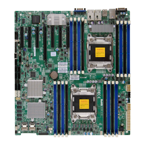
Chapter 1: Overview Chapter 1 Overview Overview Checklist Congratulations on purchasing your computer motherboard from an acknowledged leader in the industry. Supermicro boards are designed with the utmost attention to detail to provide you with the highest standards in quality and performance. Please check that the following items have all been included with your motherboard. - Page 10 X9DRH-7F/-iF/-iF-NV/-7TF/-iTF Motherboard User’s Manual Motherboard Image Note: All graphics shown in this manual were based upon the latest PCB Revision available at the time of publishing of the manual. The motherboard you've received may or may not look exactly the same as the graphics shown in this manual.
-
Page 11: Motherboard Layout
Chapter 1: Overview Motherboard Layout USB2/3 USB0/1 COM1 LAN CTRL BMC CTRL FAN5 KB/MS IPMI_LAN LAN1 LAN2 COM2 CLOSE 1st CPU2 T-SGPIO-S OPEN 1st Battery JBT1 X9DRH-7F/iF/iF-NV/7TF/iTF T-SGPIO1 BIOS Rev. 1.02 Intel IO Hub CLOSE 1st CPU1 LSI SAS CTRL OPEN 1st LEDS2 LEDS1... - Page 12 X9DRH-7F/-iF/-iF-NV/-7TF/-iTF Motherboard User’s Manual X9DRH-7F/-iF/-iF-NV/-7TF/-iTF Quick Reference USB2/3 USB0/1 COM1 LAN CTRL BMC CTRL FAN5 KB/MS IPMI_LAN LAN1 LAN2 COM2 CLOSE 1st CPU2 T-SGPIO-S OPEN 1st Battery JBT1 X9DRH-7F/iF/iF-NV/7TF/iTF T-SGPIO1 BIOS Rev. 1.02 Intel IO Hub CLOSE 1st CPU1 LSI SAS CTRL OPEN 1st LEDS2...
- Page 13 Chapter 1: Overview X9DRH-7F/-iF/-iF-NV/-7TF/-iTF Jumpers Jumper Description Default Setting JBT1 Clear CMOS See Chapter 3 C1/JI SMB to PCI-E Slots Pins 2-3 (Normal) JPB1 BMC Enable Pins 1-2 (Enabled) JPG1 VGA Enable Pins 1-2 (Enabled) JPLAN1 LAN1/LAN2 Enable Pins 1-2 (Enabled) JPME1 Management Engine Pins 1-2 (Normal)
- Page 14 X9DRH-7F/-iF/-iF-NV/-7TF/-iTF Motherboard User’s Manual LAN1/2 GLAN Ports 1/2 for -7F/-iF/iF-NV, 10GLAN Ports 1/2 for -7TF/-iTF) (IPMI) LAN IPMI_Dedicated LAN (I-)SATA 0/1 Intel SATA 3.0 Connectors 0/1 (from AHCI) (I-)SATA 2~5 Intel SATA 2.0 Connectors (from AHCI): SATA2/3 (T- SGPIO1) & SATA4/5 (T-SGPIO2) (S-)SATA 0~3 SATA 2.0 Connectors 0~3 from SCU (Storage Control Unit) (Available for RAID 0, 1, 5, 10 when used in conjunction...
-
Page 15: Motherboard Features
Chapter 1: Overview Motherboard Features • Dual Intel E5-2600 (V2) Series (Socket R) proces- ® sors; each processor supports two full-width Intel QuickPath Interconnect (QPI) links (with support of up to 8.0 GT/s per QPI link) Note: For the E5-2600 V2 CPU to work properly, please update your BIOS to BIOS R3.0. -
Page 16: Peripheral Devices
X9DRH-7F/-iF/-iF-NV/-7TF/-iTF Motherboard User’s Manual I/O Devices SATA Connections • SATA Ports (from Two (2) I-SATA 3.0 (I-SATA AHCI) 0/1), Four (4) I-SATA 2.0 Ports (I-SATA 2~5) • SATA Ports (from Four S-SATA 2.0 Ports 0~3 SCU) (From Storage Control Unit) •... - Page 17 Chapter 1: Overview • Power-on mode for AC power recovery • Intel Intelligent Power Node Manager (NM) (Avail- ® able when the NMView utility is installed in the system) • Manageability Engine (ME) PC Health CPU Monitoring • Onboard voltage monitors for +1.8V, +3.3V, 3.3VSB, Monitoring +5V, +5V Standby, 12V, Memory, Chipset and Bat- tery Voltage.
-
Page 18: System Block Diagram
X9DRH-7F/-iF/-iF-NV/-7TF/-iTF Motherboard User’s Manual #H-2 #H-1 #G-2 #D-2 #G-1 #F-2 #C-2 #F-1 #C-1 #E-2 #E-1 #B-2 #B-1 E5-2600 E5-2600 #A-2 8 SNB CORE 8 SNB CORE DDR-III DDR-III #A-1 (CPU1) (CPU2) #3A #3C DMI2 DMI2 PCI-E X16 G3 PCI-E X8 G3 PCI-E X8 G3 PCI-E X8 G3 SAS2208... -
Page 19: Processor And Chipset Overview
Chapter 1: Overview Processor and Chipset Overview Built upon the functionality and the capabilities of the Intel E5-2600 (V2) Series (Socket R) processor and the C602 PCH, the X9DRH-7F/-iF/-iF-NV/-7TF/-iTF motherboard provides the performance and feature sets required for dual_pro- cessor-based HPC/Cluster/Database servers. With support of Intel QuickPath interconnect (QPI) Technology, the X9DRH series motherboard offers point-to-point serial interconnect interface with a transfer speed of up to 8.0 GT/s, providing superb system performance. -
Page 20: Special Features
X9DRH-7F/-iF/-iF-NV/-7TF/-iTF Motherboard User’s Manual Special Features Recovery from AC Power Loss Basic I/O System (BIOS) provides a setting that determines how the system will respond when AC power is lost and then restored to the system. You can choose for the system to remain powered off (in which case you must press the power switch to turn it back on), or for it to automatically return to the power-on state. -
Page 21: Acpi Features
Chapter 1: Overview to provide you with warnings when the system temperature, CPU temperatures, voltages and fan speeds go beyond a predefined range. ACPI Features ACPI stands for Advanced Configuration and Power Interface. The ACPI specifica- tion defines a flexible and abstract hardware interface that provides a standard way to integrate power management features throughout a PC system, including its hardware, operating system and application software. -
Page 22: Super I/O
X9DRH-7F/-iF/-iF-NV/-7TF/-iTF Motherboard User’s Manual It is strongly recommended that you use a high quality power supply that meets ATX power supply Specification 2.02 or above. It must also be SSI compliant. (For more information, please refer to the website at http://www.ssiforum.org/). Additionally, in areas where noisy power transmission is present, you may choose to install a line filter to shield the computer from noise. -
Page 23: Management Engine (Me)
Chapter 1: Overview Management Engine (ME) The Management Engine, which is an ARC controller embedded in the PCH, pro- vides Server Platform Services (SPS) to your system. The services provided by SPS are different from those provided by the ME on client platforms. Overview of the Nuvoton WPCM450 Controller The Nuvoton WPCM450R Controller, a Baseboard Management Controller (BMC), supports 2D/VGA-compatible Graphic Cores with PCI interface, creating multi-media... -
Page 24: Nvdimm Memory Support (For X9Drh-If & -If-Nv)
X9DRH-7F/-iF/-iF-NV/-7TF/-iTF Motherboard User’s Manual • Provides remote Hardware Health Monitoring via IPMI. Key features • Provides Network Management Security via remote access/console redirection. • Supports the following Management tools: IPMIView, CLI (Command Line Interface) • RMCP+ protocol supported Note: For more information on IPMI configuration, please refer to the IPMI User's Guide posted on our website at http://www.supermicro.com/support/ manuals/. -
Page 25: Chapter 2 Installation
Chapter 2: Installation Chapter 2 Installation Standardized Warning Statements The following statements are industry-standard warnings, provided to warn the user of situations which have the potential for bodily injury. Should you have questions or experience difficulty, contact Supermicro's Technical Support department for assis- tance. - Page 26 X9DRH-7F/-iF/-iF-NV/-7TF/-iTF Motherboard User’s Manual Attention Danger d'explosion si la pile n'est pas remplacée correctement. Ne la remplacer que par une pile de type semblable ou équivalent, recommandée par le fabricant. Jeter les piles usagées conformément aux instructions du fabricant. ¡Advertencia! Existe peligro de explosión si la batería se reemplaza de manera incorrecta.
-
Page 27: Product Disposal
Chapter 2: Installation Product Disposal Warning! Ultimate disposal of this product should be handled according to all national laws and regulations. 製品の廃棄 この製品を廃棄処分する場合、 国の関係する全ての法律 ・ 条例に従い処理する必要が あります。 警告 本产品的废弃处理应根据所有国家的法律和规章进行。 警告 本產品的廢棄處理應根據所有國家的法律和規章進行。 Warnung Die Entsorgung dieses Produkts sollte gemäß allen Bestimmungen und Gesetzen des Landes erfolgen. -
Page 28: Static-Sensitive Devices
X9DRH-7F/-iF/-iF-NV/-7TF/-iTF Motherboard User’s Manual 경고! 이 제품은 해당 국가의 관련 법규 및 규정에 따라 폐기되어야 합니다. Waarschuwing De uiteindelijke verwijdering van dit product dient te geschieden in overeenstemming met alle nationale wetten en reglementen. Static-Sensitive Devices Electrostatic Discharge (ESD) can damage electronic com ponents. To avoid dam- aging your system board, it is important to handle it very carefully. -
Page 29: Processor And Heatsink Installation
Chapter 2: Installation Processor and Heatsink Installation Warning: When handling the processor package, avoid placing direct pressure on the label area. Notes: • Always connect the power cord last, and always remove it before adding, removing or changing any hardware components. Make sure that you install the processor into the CPU socket before you install the CPU heatsink. - Page 30 X9DRH-7F/-iF/-iF-NV/-7TF/-iTF Motherboard User’s Manual 2. Press the second load lever labeled 'Close 1st' to release the load plate that covers the CPU socket from its locking position. Pull lever away from Press down on Load the the socket Lever labeled 'Close 1st' 3.
- Page 31 Chapter 2: Installation 1. Use your index fingers to loosen the lever and open the load plate. 2. Use your thumb and index finger to hold the CPU on its edges. Align the CPU keys, which are semi-circle cutouts, against the socket keys. Socket Keys CPU Keys 3.
- Page 32 X9DRH-7F/-iF/-iF-NV/-7TF/-iTF Motherboard User’s Manual 4. With the CPU inside the socket, inspect the four corners of the CPU to make sure that the CPU is properly installed. 5. Close the load plate with the CPU inside the socket. Lock the lever labeled 'Close 1st' first, then lock the lever labeled 'Open 1st' second.
-
Page 33: Installing A Passive Cpu Heatsink
Chapter 2: Installation Installing a Passive CPU Heatsink 1. Do not apply any thermal grease to the heatsink or the CPU die -- the re- quired amount has already been applied. 2. Place the heatsink on top of the CPU so that the four mounting holes are aligned with those on the Motherboard's and the Heatsink Bracket under- neath. -
Page 34: Removing The Heatsink
X9DRH-7F/-iF/-iF-NV/-7TF/-iTF Motherboard User’s Manual Removing the Heatsink Warning: We do not recommend that the CPU or the heatsink be removed. However, if you do need to uninstall the heatsink, please follow the instructions below to uninstall the heatsink to prevent damage done to the CPU or the CPU socket. 1. -
Page 35: Installing And Removing The Memory Modules
Chapter 2: Installation Installing and Removing the Memory Modules Note: Check Supermicro's Website for recommended memory modules. CAUTION Exercise extreme care when installing or removing DIMM modules to prevent any possible damage. Installing & Removing DIMMs 1. Insert the desired number of DIMMs into the memory slots, starting with P1- DIMM #A1. - Page 36 X9DRH-7F/-iF/-iF-NV/-7TF/-iTF Motherboard User’s Manual Memory Support for the X9DRH-7F/-iF/-iF-NV/-7TF/-iTF Motherboard This motherboard supports up to 1TB of 240-pin Registered (RDIMM)/Load Reduced /(LRDIMM)/Non-Volatile (NVDIMM) ECC or Unbuffered (UDIMM) ECC/ Non-ECC DDR3 1866/1600/1333/1066/800 MHz memory in 16 slots (1866 MHz is not available on NVDIMMs.) Note 1: For the latest memory updates, please refer to our website at http://www.supermicro.com/products/motherboard.
-
Page 37: Installing Udimms On The Mb With The E5-2600 Processors Onboard
Chapter 2: Installation Populating UDIMM (ECC/Non-ECC) Memory Modules Installing UDIMMs on the MB with the E5-2600 Processors Onboard Intel E5-2600 Series Processor UDIMM Memory Support Ranks Per Memory Capacity Speed (MHz) and Voltage Validated by Slot per Channel DIMM & Per DIMM (SPC) and DIMM Per Channel (DPC) Data Width... -
Page 38: Installing Rdimms On The Mb With The E5-2600 Processors Onboard
X9DRH-7F/-iF/-iF-NV/-7TF/-iTF Motherboard User’s Manual Populating RDIMM (ECC) Memory Modules Installing RDIMMs on the MB with the E5-2600 Processors Onboard Intel E5-2600 Series Processor RDIMM Memory Support Ranks Memory Capacity Speed (MHz) and Voltage Validated by Slot per Channel (SPC) and Per DIMM DIMM Per Channel (DPC) DIMM... -
Page 39: Installing Lrdimms On The Mb With The E5-2600 Processors Onboard
Chapter 2: Installation Populating LRDIMM (ECC) Memory Modules Installing LRDIMMs on the MB with the E5-2600 Processors Onboard Intel E5-2600 Series Processor LRDIMM Memory Support Ranks Per Memory Capacity Speed (MHz) and Voltage Validated DIMM & Data Per DIMM by Slot per Channel (SPC) and Width DIMM Per Channel (DPC) 1 Slot Per... -
Page 40: Motherboard Installation
X9DRH-7F/-iF/-iF-NV/-7TF/-iTF Motherboard User’s Manual Motherboard Installation All motherboards have standard mounting holes to fit different types of chassis. Make sure that the locations of all the mounting holes for both motherboard and chassis match. Although a chassis may have both plastic and metal mounting fas- teners, metal ones are highly recommended because they ground the motherboard to the chassis. -
Page 41: Installing The Motherboard
Chapter 2: Installation Installing the Motherboard 1. Install the I/O shield into the chassis. 2. Locate the mounting holes on the motherboard. 3. Locate the matching mounting holes on the chassis. Align the mounting holes on the motherboard with the mounting holes on the chassis. 4. -
Page 42: Control Panel Connectors And I/O Ports
X9DRH-7F/-iF/-iF-NV/-7TF/-iTF Motherboard User’s Manual Control Panel Connectors and I/O Ports The I/O ports are color coded in conformance with the PC 99 specification. See the picture below for the colors and locations of the various I/O ports. Back Panel Connectors and I/O Ports X9DRH-7F/iF/iF-NV/7TF/iTF Rev. -
Page 43: Universal Serial Bus (Usb)
Chapter 2: Installation Universal Serial Bus (USB) FP USB (4/5, 6) Backplane USB Pin Definitions (USB 0/1, 2/3) Four Universal Serial Bus ports (USB Pin Definitions USB 4, 6 USB 5 0/1, 2/3) are located on the I/O back Pin # Definition Pin # Definition Pin# Definition panel. -
Page 44: Serial Ports
X9DRH-7F/-iF/-iF-NV/-7TF/-iTF Motherboard User’s Manual Serial Ports Serial COM) Ports Pin Definitions Two COM connections (COM1 & Pin # Definition Pin # Definition COM2) are located on the mother- board. COM1 is located on the Back- plane I/O panel. COM2, located next to the IPMB header, is used to provide front access support. -
Page 45: Ethernet Ports
Chapter 2: Installation Ethernet Ports LAN Ports Pin Definition Two Gigabit Ethernet ports (LAN1/2) Pin# Definition are located on the I/O backplane on P2V5SB SGND the motherboard to provide inter- TD0+ Act LED net connections. LAN1/LAN2 ports TD0- P3V3SB support 1GLAN connections on the TD1+ Link 100 LED (Yel- X9DRH-7F/iF/iF-NV models, and... -
Page 46: Front Control Panel
X9DRH-7F/-iF/-iF-NV/-7TF/-iTF Motherboard User’s Manual Front Control Panel JF1 contains header pins for various buttons and indicators that are normally lo- cated on a control panel at the front of the chassis. These connectors are designed specifically for use with Supermicro's server chassis. See the figure below for the descriptions of the various control panel buttons and LED indicators. -
Page 47: Front Control Panel Pin Definitions
Chapter 2: Installation Front Control Panel Pin Definitions NMI Button NMI Button Pin Definitions (JF1) The non-maskable interrupt button Pin# Definition header is located on pins 19 and 20 Control of JF1. Refer to the table on the right Ground for pin definitions. Power LED Power LED Pin Definitions (JF1) The Power LED connection is located Pin#... -
Page 48: Hdd Led
X9DRH-7F/-iF/-iF-NV/-7TF/-iTF Motherboard User’s Manual HDD LED HDD LED Pin Definitions (JF1) The HDD LED connection is located Pin# Definition on pins 13 and 14 of JF1. Attach a 3.3V Standby cable here to indicate HDD activ- HD Active ity. See the table on the right for pin definitions. -
Page 49: Overheat (Oh)/Fan Fail Led
Chapter 2: Installation Overheat (OH)/Fan Fail LED OH/Fan Fail/PWR Fail LED Pin Definitions (JF1) Connect an LED cable to pins 7 and 8 Pin# Definition of JF1 to provide advanced warnings of chassis overheating and fan failure. OH/Fan Fail LED) Refer to the table on the right for pin definitions. -
Page 50: Reset Button
X9DRH-7F/-iF/-iF-NV/-7TF/-iTF Motherboard User’s Manual Reset Button Reset Button Pin Definitions (JF1) The Reset Button connection is located Pin# Definition on pins 3 and 4 of JF1. Attach it to a Reset hardware reset switch on the computer Ground case. Refer to the table on the right for pin definitions. -
Page 51: Connecting Cables
Chapter 2: Installation Connecting Cables ATX Power 24-pin Connector Pin Definitions Pin# Definition Pin # Definition Power Connectors +3.3V +3.3V -12V +3.3V A 24-pin main power supply connector(J22) and two 8-pin power connectors (JPWR1/JPWR2) PS_ON are located on the motherboard. These power connectors meet the SSI EPS 12V specifica- tion. -
Page 52: Fan Headers
X9DRH-7F/-iF/-iF-NV/-7TF/-iTF Motherboard User’s Manual Fan Headers Fan Header Pin Definitions This motherboard has six system/CPU Pin# Definition fan headers (Fan 1~Fan 6, Fan A/Fan B) Ground on the motherboard. All these 4-pin fans +12V headers are backward compatible with Tachometer the traditional 3-pin fans. However, fan PWR (Pulse Width speed control is available for 4-pin fans Modulation) -
Page 53: Internal Speaker
Chapter 2: Installation Internal Speaker Internal Buzzer (SP1) Pin Definition The Internal Speaker, located at SP1, Pin# Definitions can be used to provide audible indica- Pin 1 Pos. (+) Beep In tions for various beep codes. See the Pin 2 Neg. (-) Alarm table on the right for pin definitions. -
Page 54: Tpm Header/Port 80 Header
X9DRH-7F/-iF/-iF-NV/-7TF/-iTF Motherboard User’s Manual TPM Header/Port 80 Header TPM/Port 80 Header Pin Definitions A Trusted Platform Module/Port 80 Pin # Definition Pin # Definition header is located at JTPM1 to provide LCLK TPM support and Port 80 connection. LFRAME# <(KEY)> Use this header to enhance system LRESET# +5V (X) performance and data security. -
Page 55: Power Smb (I 2 C) Connector
Chapter 2: Installation Power SMB (I C) Connector PWR SMB Pin Definitions Power System Management Bus (I Pin# Definition Connector (JPI C1) monitors power Clock supply, fan and system temperatures. Data See the table on the right for pin PWR Fail definitions. -
Page 56: T-Sgpio1/2/T-Sgpio-S Headers
X9DRH-7F/-iF/-iF-NV/-7TF/-iTF Motherboard User’s Manual T-SGPIO1/2/T-SGPIO-S Headers T-SGPIO Pin Definitions Two SGPIO (Serial Link General Pin# Definition Definition Purpose Input/Output) headers are located at T-SGPIO1/2 on the moth- Ground Data erboard to support I-SATA 0~5 ports. Load Ground Additionally, T-SGPIO-S supports S- Clock SATA 0~3 ports. -
Page 57: Battery Backup Unit (Optional For The X9Drh-7F/7Tf Only)
Chapter 2: Installation Battery Backup Unit (Optional for the X9DRH-7F/7TF Only) Pin Definitions Definition Definition An onboard SAS Battery-Backup Unit (BBU) Inplace2 Inplace1 connector is located at JS3 on the mother- board. The BBU provides battery backup +12V support for onboard SAS to prevent data loss Ground Ground during a power outage. -
Page 58: Jumper Settings
X9DRH-7F/-iF/-iF-NV/-7TF/-iTF Motherboard User’s Manual Jumper Settings Explanation of Jumpers Connector Pins To modify the operation of the motherboard, jumpers can be used to choose between optional settings. Jumpers create shorts be- Jumper tween two pins to change the function of the connector. -
Page 59: Cmos Clear
Chapter 2: Installation CMOS Clear JBT1 is used to clear CMOS. Instead of pins, this "jumper" consists of contact pads to prevent accidental clearing of CMOS. To clear CMOS, use a metal object such as a small screwdriver to touch both pads at the same time to short the connection. Always remove the AC power cord from the system before clearing CMOS. -
Page 60: Vga Enable
X9DRH-7F/-iF/-iF-NV/-7TF/-iTF Motherboard User’s Manual VGA Enable VGA Enable Jumper Settings Jumper JPG1 allows the user to en- Jumper Setting Definition able the onboard VGA connectors. The Enabled (Default) default setting is 1-2 to enable the con- Disabled nection. See the table on the right for jumper settings. -
Page 61: Management Engine (Me) Recovery
Chapter 2: Installation Management Engine (ME) Recovery ME Recovery Jumper Settings Use Jumper JPME1 to select ME Firm- Jumper Setting Definition ware Recovery mode, which will limit Normal (Default) resource allocation for essential system ME Recovery operation only in order to maintain nor- mal power operation and management. -
Page 62: Sas Enable
X9DRH-7F/-iF/-iF-NV/-7TF/-iTF Motherboard User’s Manual SAS Enable SAS Enable Jumper Settings Jumper JPS1 allows the user to enable Jumper Setting Definition SAS connections. The default setting is Enabled (Default) on 1-2 to enable the connection. See the Disabled table on the right for jumper settings. A. - Page 63 Chapter 2: Installation C Bus to PCI-Exp. Slots C to PCI-Exp Jumper Settings Jumpers JI C1 and JI C2 allow you Jumper Setting Definition to connect the System Management Closed Enabled Bus (I C) to PCI-Express slots. The Open Disabled (Default) default setting is Open to disable the connection.
-
Page 64: Onboard Led Indicators
X9DRH-7F/-iF/-iF-NV/-7TF/-iTF Motherboard User’s Manual Onboard LED Indicators Link LED Activity LED GLAN LEDs The LAN 1/2 ports are located on the IO Rear View (when facing the rear side of the chassis) Backplane. Please note that LAN1/LAN2 GLAN Activity Indicator (Left) support 10GLAN connections on the -7TF/ LED Settings iTF models, and support 1GLAN for the... -
Page 65: Onboard Power Led
Chapter 2: Installation Onboard Power LED Onboard PWR LED Indicator (LE1) LED Settings An Onboard Power LED is located at LE1 LED Color Status on the motherboard. When this LED is on, System Off (PWR cable not connected) the system is on. Be sure to turn off the Green System On system and unplug the power cord before... -
Page 66: Sas Activity Led
X9DRH-7F/-iF/-iF-NV/-7TF/-iTF Motherboard User’s Manual SAS Activity LED SAS LED Status A SAS Activity LED is located at LEDS1 Color/State Definition on the motherboard. When LEDS1 is Green: SAS: Active blinking, SAS is active. See the table at Blinking right for more information. SAS Fault LED SAS LED Status... -
Page 67: 2-10 Serial Ata Connections
Chapter 2: Installation 2-10 Serial ATA Connections Serial ATA Ports Serial ATA2/SAS3 Pin Definitions There are ten Serial ATA Ports (I-SATA0~I- Pin# Definition SATA 5) located on the motherboard, in- Ground cluding eight SATA2 ports (I-SATA2~5, S- TX_P SATA0~3) and two SATA3 ports (I-SATA0~1). TX_N These ports provide Serial Link signal connec- Ground... - Page 68 X9DRH-7F/-iF/-iF-NV/-7TF/-iTF Motherboard User’s Manual Notes 2-44...
-
Page 69: Chapter 3 Troubleshooting
Chapter 3: Troubleshooting Chapter 3 Troubleshooting Troubleshooting Procedures Use the following procedures to troubleshoot your system. If you have followed all of the procedures below and still need assistance, refer to the ‘Technical Support Procedures’ and/or ‘Returning Merchandise for Service’ section(s) in this chapter. Note: Always disconnect the power cord before adding, changing or installing any hardware components. -
Page 70: System Boot Failure
X9DRH-7F/-iF/-iF-NV/-7TF/-iTF Motherboard User's Manual No Video 1. If the power is on, but you have no video, remove all the add-on cards and cables. 2. Use the speaker to determine if any beep codes exist. Refer to Appendix A for details on beep codes. System Boot Failure If the system does not display POST or does not respond after the power is turned on, check the following:... -
Page 71: Memory Errors
Chapter 3: Troubleshooting Memory Errors When a No_Memory_Beep_Code is issued by the system, check the following: 1. Make sure that the memory modules are compatible with the system and that the DIMM modules are properly and fully installed. (For memory compatibility, refer to the Memory Compatibility Chart posted on our Website @ http://www. - Page 72 X9DRH-7F/-iF/-iF-NV/-7TF/-iTF Motherboard User's Manual range. Also check the front panel Overheat LED, and make sure that the Overheat LED is not on. 5. Adequate power supply: Make sure that the power supply provides adequate power to the system. Make sure that all power connectors are connected. Please refer to our website for more information on minimum power require- ment.
-
Page 73: Technical Support Procedures
Chapter 3: Troubleshooting Technical Support Procedures Before contacting Technical Support, please take the following steps. Also, please note that as a motherboard manufacturer, Supermicro also sells motherboards through its channels, so it is best to first check with your distributor or reseller for troubleshooting services. -
Page 74: Battery Removal And Installation
X9DRH-7F/-iF/-iF-NV/-7TF/-iTF Motherboard User's Manual Battery Removal and Installation Battery Removal To remove the onboard battery, follow the steps below: 1. Power off your system and unplug your power cable. 2. Locate the onboard battery as shown below. 3. Using a tool such as a pen or a small screwdriver, push the battery lock out- wards to unlock it. -
Page 75: Frequently Asked Questions
Chapter 3: Troubleshooting Frequently Asked Questions Question: What are the various types of memory that my motherboard can support? Answer: The motherboard supports Registered (RDIMM)/Load Reduced / (LRDIMM)/Non-Volatile (NVDIMM) ECC or Unbuffered (UDIMM) ECC/Non-ECC DDR3 DIMM modules. It is strongly recommended that you do not mix memory modules of different speeds and sizes. -
Page 76: Returning Merchandise For Service
X9DRH-7F/-iF/-iF-NV/-7TF/-iTF Motherboard User's Manual Returning Merchandise for Service A receipt or copy of your invoice marked with the date of purchase is required before any warranty service will be rendered. You can obtain service by calling your ven- dor for a Returned Merchandise Authorization (RMA) number. When returning the motherboard to the manufacturer, the RMA number should be prominently displayed on the outside of the shipping carton, and the shipping package is mailed prepaid or hand-carried. -
Page 77: Chapter 4 Bios
Chapter 4: AMI BIOS Chapter 4 BIOS Introduction This chapter describes the AMI BIOS Setup utility for the X9DRH-7F/-iF/-iF-NV/- 7TF/-iTF. It also provides the instructions on how to navigate the AMI BIOS Setup utility screens. The AMI ROM BIOS is stored in a Flash EEPROM and can be easily updated. -
Page 78: Starting The Setup Utility
X9DRH-7F/-iF/-iF-NV/-7TF/-iTF Motherboard User’s Manual How To Change the Configuration Data The configuration data that determines the system parameters may be changed by entering the AMI BIOS Setup utility. This Setup utility can be accessed by pressing <Delete> at the appropriate time during system boot. Note: For AMI UEFI BIOS Recovery, please refer to the UEFI BIOS Re- covery User Guide posted @http://www.supermicro.com/support/manuals/. - Page 79 Chapter 4: AMI BIOS System Time/System Date Use this option to change the system time and date. Highlight System Time or System Date using the arrow keys. Enter new values through the keyboard and press <Enter>. Press the <Tab> key to move between fields. The date must be entered in Day MM/DD/YY format.
-
Page 80: 4-3 Advanced Setup Configurations
X9DRH-7F/-iF/-iF-NV/-7TF/-iTF Motherboard User’s Manual 4-3 Advanced Setup Configurations Use the arrow keys to select Advanced and press <Enter> to access the following submenu items: Boot Feature Quiet Boot Set this value to allow the bootup screen options to be modified between POST messages or the OEM logo. -
Page 81: Socket 0 Cpu Information
Chapter 4: AMI BIOS Interrupt 19 Capture Interrupt 19 is the software interrupt that handles the boot disk function. When this item is set to Enabled, the ROM BIOS of the host adaptors will "capture" Interrupt 19 at boot and allow the drives that are attached to these host adaptors to function as bootable disks. -
Page 82: Socket 1 Cpu Information
X9DRH-7F/-iF/-iF-NV/-7TF/-iTF Motherboard User’s Manual • CPU Stepping • Maximum CPU Speed • Minimum CPU Speed • Processor Cores • Intel HT(Hyper-Threading) Technology • Intel VT-x (Virtualization) Technology • L1 Data Cache • L1 Code Cache • L2 Cache • L3 Cache Socket 1 CPU Information ... - Page 83 Chapter 4: AMI BIOS Execute-Disable Bit Capability (Available if supported by the OS & the CPU) Set to Enabled to enable the Execute Disable Bit, which will allow the processor to designate areas in the system memory where an application code can execute and where it cannot, thus preventing a worm or a virus from flooding illegal codes to overwhelm the processor or damage the system during an attack.
- Page 84 X9DRH-7F/-iF/-iF-NV/-7TF/-iTF Motherboard User’s Manual Power Technology Select Energy Efficient to support power-saving mode. Select Custom to custom- ize system power settings. Select Disabled to disable power-saving settings. The options are Disable, Energy Efficient and Custom. If Custom is selected, the following options become available: EIST EIST (Enhanced Intel SpeedStep Technology) allows the system to auto-...
- Page 85 Chapter 4: AMI BIOS Package C State Limit If set to Auto, the AMI BIOS will automatically set the limit on the C-State package register. The options are C0, C2, C6, C7, and No Limit. Energy/Performance Bias Use this feature to select an appropriate fan setting to achieve maximum system performance (with maximum cooling) or maximum energy efficiency with maxi- mum power saving).
-
Page 86: North Bridge
X9DRH-7F/-iF/-iF-NV/-7TF/-iTF Motherboard User’s Manual Chipset Configuration North Bridge This feature allows the user to configure the settings for the Intel North Bridge. IOH (IO Hub) Configuration Intel VT-d ® Select Enabled to enable Intel Virtualization Technology support for Direct I/O VT-d by reporting the I/O device assignments to the VMM (Virtual Machine Monitor) through the DMAR ACPI Tables. - Page 87 Chapter 4: AMI BIOS IOU2 - PCIe Port This feature allows the user to set the PCI-Exp bus speed between IOU2 and PCIe port. The default setting is x8x8. Slot 2 Link Speed Select GEN1 to enable PCI-Exp Generation 1 support for Slot 2 Port. Select GEN2 to enable PCI-Exp Generation 2 support for Slot 2 Port.
- Page 88 X9DRH-7F/-iF/-iF-NV/-7TF/-iTF Motherboard User’s Manual Current QPI Link Frequency This item displays the current frequency of the QPI Link. Isoc Select Enabled to enable Isochronous support to meet QoS (Quality of Service) requirements. This feature is especially important for virtualization technology. The options are Disabled and Enabled.
- Page 89 Chapter 4: AMI BIOS DDR Speed Use this feature to force a DDR3 memory module to run at a frequency other than what is indicated in the system specification. The options are Auto, Force DDR3- 800, Force DDR3-1066, Force DDR3-1333, Force DOR3-1600 and Force SPD. Channel Interleaving This feature selects from the different channel interleaving methods.
-
Page 90: South Bridge
X9DRH-7F/-iF/-iF-NV/-7TF/-iTF Motherboard User’s Manual Thermal Throttling Throttling improves reliability and reduces power consumption in the proces- sor via automatic voltage control during processor idle states. The options are Disabled and CLTT (Closed Loop Thermal Throttling). South Bridge This feature allows the user to configure the settings for the Intel PCH chip. PCH Information This item displays the following PCH information. - Page 91 Chapter 4: AMI BIOS SATA Configuration When this submenu is selected, the AMI BIOS automatically detects the presence of IDE or SATA devices and displays the following items. SATA Port0~SATA Port5 The AMI BIOS displays the status of each SATA port as detected by the BIOS. SATA Mode Use this feature to configure SATA mode for a selected SATA port.
- Page 92 X9DRH-7F/-iF/-iF-NV/-7TF/-iTF Motherboard User’s Manual RAID Mode The following items are displayed when RAID Mode is selected: Port 0~5 Hot Plug Select Enabled to enable hot-plug support for a port specified by the user. The options are Enabled and Disabled. SCU Configuration ...
- Page 93 Chapter 4: AMI BIOS PERR# Generation Select Enabled to allow a PCI device to generate a PERR number for a PCI Bus Signal Error Event. The options are Enabled and Disabled. SERR# Generation Select Enabled to allow a PCI device to generate a SERR number for a PCI Bus Signal Error Event.
- Page 94 X9DRH-7F/-iF/-iF-NV/-7TF/-iTF Motherboard User’s Manual VGA Priority Use this feature to specify which graphics controller to be used as the primary boot device. The options are Onboard and Offboard (VGA). Network Stack Select Enabled to enable PXE (Preboot Execution Environment) or UEFI (Unified Extensible Firmware Interface) for network stack support.
-
Page 95: Serial Port Console Redirection
Chapter 4: AMI BIOS Device Settings This item displays the settings of Serial Port 2. Change Settings This option specifies the base I/O port address and the Interrupt Request address of Serial Port 2. Select Disabled to prevent the serial port from accessing any system resources. - Page 96 X9DRH-7F/-iF/-iF-NV/-7TF/-iTF Motherboard User’s Manual Bits Per Second This item sets the transmission speed for a serial port used in Console Redirec- tion. Make sure that the same speed is used in the host computer and the client computer. A lower transmission speed may be required for long and busy lines. The options are 9600, 19200, 38400, 57600, and 115200 (bits per second).
-
Page 97: Console Redirection Settings (For Ems)
Chapter 4: AMI BIOS Resolution 100x31 Select Enabled for extended-terminal resolution support. The options are Dis- abled and Enabled. Legacy OS Redirection Use this feature to select the number of rows and columns used in Console Redirection for legacy OS support. The options are 80x24 and 80x25. Putty Keypad Use this feature to select function key and keypad setting on Putty. -
Page 98: Acpi Settings
X9DRH-7F/-iF/-iF-NV/-7TF/-iTF Motherboard User’s Manual Flow Control This feature allows the user to set the flow control for Console Redirection to prevent data loss caused by buffer overflow. Send a "Stop" signal to stop send- ing data when the receiving buffer is full. Send a "Start" signal to start sending data when the receiving buffer is empty. - Page 99 Chapter 4: AMI BIOS TPM State Select Enabled to enable TPM security settings to improve data integrity and network security. The options are Disabled and Enabled. Pending Operation Use this item to schedule an operation for the security device. The options are None, Enable Take Ownership, Disable Take Ownership, and TPM Clear.
- Page 100 X9DRH-7F/-iF/-iF-NV/-7TF/-iTF Motherboard User’s Manual Intel TXT (LT-SX) Dependencies This feature displays the features that need to be enabled for the Intel Trusted Execution Technology to work properly in the system. VT-d Support: Intel Virtualization Technology with Direct I/O support VT Support: Intel Virtualization Technology support TPM Support: Trusted Platform support TPM State: Trusted Platform state ME (Management Engine) Subsystem...
-
Page 101: Event Logs
Chapter 4: AMI BIOS Event Logs Use this menu to configure Event Log settings. Change SmBIOS Event Log Settings Enabling/Disabling Options Smbios Event Log Change this item to enable or disable all features of the Smbios Event Logging during boot. The options are Enabled and Disabled. Runtime Error Logging Support Change this item to enable or disable runtime error logging. - Page 102 X9DRH-7F/-iF/-iF-NV/-7TF/-iTF Motherboard User’s Manual Erasing Settings Erase Event Log Select Enabled to erase the SMBIOS (System Management BIOS) Event Log, which is completed before a event logging is initialized upon system reboot. The options are No, Yes, Next reset, and Yes, Every reset. When Log is Full This option automatically clears the Event Log memory of all messages when it is full.
-
Page 103: Ipmi
Chapter 4: AMI BIOS IPMI Use this menu to configure Intelligent Platform Management Interface (IPMI) set- tings. System Event Log Enabling/Disabling Options SEL Components Select Enabled for all system event logging at bootup. The options are Enabled and Disabled. Erasing Settings Erase SEL Select 'Yes, On next reset' to erase all system event logs upon next system reboot. - Page 104 X9DRH-7F/-iF/-iF-NV/-7TF/-iTF Motherboard User’s Manual Log EFI Status Codes Select Enabled to log EFI (Extensible Firmware Interface) Status Codes, Error Codes or Progress Codes. The options are disabled an Enabled. Note: After making changes on a setting, be sure to reboot the system for the changes to take effect.
-
Page 105: Boot
Chapter 4: AMI BIOS Boot This menu allows the user to configure the following boot settings for the system. Boot Option Priorities Boot Option #1/ Boot Option #2/ Boot Option #3 Use this feature to specify the sequence of boot device priority. Network Device BBS Priorities This option sets the order of the legacy network devices detected by the mother- board. -
Page 106: Security
X9DRH-7F/-iF/-iF-NV/-7TF/-iTF Motherboard User’s Manual Security This menu allows the user to configure the following security settings for the system. Administrator Password Use this feature to set the Administrator Password which is required to enter the BIOS setup utility. The length of the password should be from 3 characters to 20 characters long. -
Page 107: Save & Exit
Chapter 4: AMI BIOS Save & Exit This menu allows the user to configure the Save and Exit settings for the system. Discard Changes and Exit Select this option to quit the BIOS Setup without making any permanent changes to the system configuration, and reboot the computer. Select Discard Changes and Exit, and press <Enter>. - Page 108 X9DRH-7F/-iF/-iF-NV/-7TF/-iTF Motherboard User’s Manual Discard Changes Select this feature and press <Enter> to discard all the changes and return to the BIOS setup. When the dialog box appears, asking you if you want to load previ- ous values, select Yes to load the values previous saved, or select No to keep the changes you've made so far.
-
Page 109: Appendix A Bios Error Beep Codes
Appendix A: BIOS POST Error Codes Appendix A BIOS Error Beep Codes During the POST (Power-On Self-Test) routines, which are performed at each system boot, errors may occur. Non-fatal errors are those which, in most cases, allow the system to continue to boot. - Page 110 X9DRH-7F/-iF/-iF-NV/-7TF/-iTF User's Manual Notes...
-
Page 111: Appendix B Software Installation Instructions
Appendix B: Software Installation Instructions Appendix B Software Installation Instructions B-1 Installing Software Programs After you've installed the operating system, a screen as shown below will appear. You are ready to install software programs and drivers that have not yet been in- stalled. -
Page 112: Configuring Superdoctor Iii
X9DRH-7F/-iF/-iF-NV/-7TF/-iTF Motherboard User's Manual B-2 Configuring SuperDoctor III The SuperDoctor® III program is a Web-based management tool that supports remote management capability. It includes Remote and Local Management tools. The local management is called the SD III Client. The SuperDoctor® III program included on the CDROM that came with your motherboard allows you to monitor the environment and operations of your system. - Page 113 Appendix B: Software Installation Instructions SuperDoctor® III Interface Display Screen-II (Remote Control) Note: The SDIII utility and the user guide can be downloaded from our website at: http://www.supermicro.com/products/accessories/software/ SuperDoctorIII.cfm. For Linux, we will still recommend that you use SuperDoctor II.
- Page 114 X9DRH-7F/-iF/-iF-NV/-7TF/-iTF Motherboard User's Manual Notes...
- Page 115 (Disclaimer Continued) The products sold by Supermicro are not intended for and will not be used in life support systems, medical equipment, nuclear facilities or systems, aircraft, aircraft devices, aircraft/emergency communication devices or other critical systems whose failure to perform be reasonably expected to result in significant injury or loss of life or catastrophic property damage.
Need help?
Do you have a question about the SuperO X9DRH-7F and is the answer not in the manual?
Questions and answers