Sign In
Upload
Manuals
Brands
Data Translation Manuals
Measuring Instruments
DT9837A
Data Translation DT9837A Manuals
Manuals and User Guides for Data Translation DT9837A. We have
1
Data Translation DT9837A manual available for free PDF download: User Manual
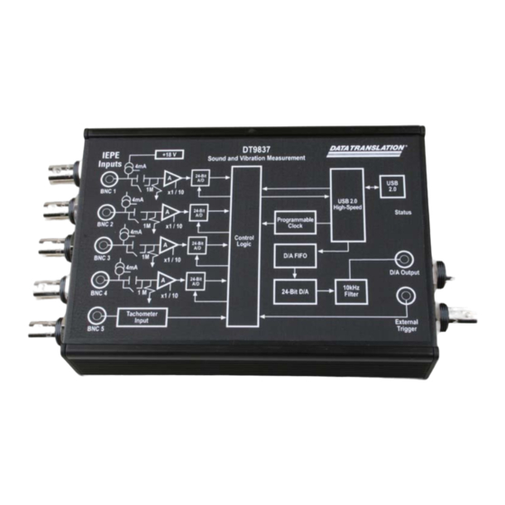
Data Translation DT9837A User Manual (150 pages)
DT9837 Series high-performance, multifunction data acquisition modules for the USB (Ver. 2.0 or Ver. 1.1) bus.
Brand:
Data Translation
| Category:
Measuring Instruments
| Size: 1.59 MB
Table of Contents
Table of Contents
5
About this Manual
9
How this Manual Is Organized
9
Intended Audience
9
Conventions Used in this Manual
10
Related Information
10
Where to Get Help
11
Chapter 1: Overview
13
Hardware Features
14
Key Features of the DT9837
15
Key Features of the DT9837A
16
Key Features of the DT9837B
18
Key Features of the DT9837C
19
Supported Software
21
Supported Accessories
24
Getting Started Procedure
25
Part 1: Getting Started
27
Getting Started Procedure
27
Chapter 2: Setting up and Installing the Module
29
Unpacking
31
System Requirements
32
Attaching Modules to the Computer
33
Connecting Directly to the USB Ports
33
Connecting to an Expansion Hub
34
Configuring the DT9837 Series Device Drivers
36
Chapter 3: Wiring Signals
39
Preparing to Wire Signals
41
Wiring Recommendations
41
Wiring Signals to the Module
41
Connecting Analog Input Signals
44
Connecting an Analog Output Signal
45
Connecting a Tachometer Input Signal
46
Connecting a Gate Input Signal
47
Chapter 4: Verifying the Operation of a Module
49
Select the Device
51
Acquire Data from an Analog Output Channel
54
Configure the Analog Output Settings
54
Configure the Analog Input Channel
55
Configure the Recording Settings
57
Configure the Acquisition Settings
58
Start the Operation
59
Part 2: Using Your Module
61
Chapter 5: Principles of Operation
63
Analog Input Features
68
Analog Input Channels
68
Input Ranges and Gains
69
IEPE Functions
69
Input Resolution
69
Input Clock Source
69
Analog Input Conversion Modes
70
Single-Value Operations
70
Single-Values Operations
71
Continuous Scan Mode
71
Input Triggers
73
Start Trigger Sources
73
Reference Trigger Sources
74
Data Format and Transfer
75
Error Conditions
75
Analog Output Features
76
Analog Output Channels
76
Output Ranges and Gains
76
Output Resolution
76
Output Clocks
76
Output Conversion Modes
77
Single-Value Mode
77
Waveform Generation Mode
77
Continuous Analog Output Operations
78
(DT9837A Only)
79
Output Trigger
80
Data Format and Transfer
80
Error Conditions
81
Tachometer Input Features
82
Frequency or Period Measurements - Tachometer Counter 0
82
Phase Measurements - Tachometer Counter 1
84
Gate Input Features
85
Triggering Acquisition on Multiple Modules
86
Synchronizing Acquisition on Multiple DT9837A, DT9837B, or DT9837C Modules
87
Chapter 6: Supported Device Driver Capabilities
91
Options
92
Data Flow and Operation Options
93
Buffering
94
Triggered Scan Mode
94
Data Encoding
94
Channels
95
Gain
95
Ranges
96
Resolution
96
Current and Resistance Support
96
Thermocouple, RTD, and Thermistor Support
97
IEPE Support
98
Bridge and Strain Gage Support
98
Start Triggers
99
Reference Triggers
100
Clocks
101
Counter/Timers
102
Tachometer
103
Chapter 7: Troubleshooting
105
General Checklist
106
Technical Support
108
If Your Module Needs Factory Service
109
Chapter 8: Calibration
111
Using the Calibration Utility
113
Calibrating the Analog Input Subsystem
114
Connecting a Precision Voltage Source
114
Using the Auto-Calibration Procedure
114
Using the Manual Calibration Procedure
115
Calibrating the Analog Output Subsystem
116
Appendix A: Specifications
117
Analog Input Specifications
118
Analog Output Specifications
121
Specifications
121
Tachometer Input Specifications
123
Gate Input Specifications
124
Trigger Specifications
125
Master Oscillator Specifications
126
Power, Physical, and Environmental Specifications
127
Regulatory Specifications
128
Connector Specifications
129
Appendix B: Connector Pin Assignments and LED Status Indicators
131
RJ45 (LVDS) Connector
132
Gate Input Connector
133
LED Status Indicators
134
Appendix C: Register-Level Programming
135
DT9837 Register-Level Programming
136
Writing to the General Control Register 2
136
Writing to EEPROM to Change the Coupling Type and Current Source
137
Writing to EEPROM to Change the High Power Mode
138
DT9837A, DT9837B, and DT9837C Register-Level Programming
140
Writing to the General Control Register 4
140
Writing to EEPROM
142
Index
145
Advertisement
Advertisement
Related Products
Data Translation DT9837
Data Translation DT9837B
Data Translation DT9837C
Data Translation DT9871U
Data Translation DT9872
Data Translation DT9800-EC-1 Series
Data Translation DT9812-10V
Data Translation DT9812-10V-OEM
Data Translation DT9813A
Data Translation DT9814-10V
Data Translation Categories
Media Converter
Computer Hardware
Control Unit
Measuring Instruments
I/O Systems
More Data Translation Manuals
Login
Sign In
OR
Sign in with Facebook
Sign in with Google
Upload manual
Upload from disk
Upload from URL