Therma-Stor Quest 185 Cool Installation, Operation And Maintanance Manual
Hide thumbs
Also See for Quest 185 Cool:
Table of Contents
Advertisement
Quick Links
Quest 185 Cool
Installation, Operation and Maintenance Instructions
Installation, Operation and Maintenance Instructions
– Read and Save These Instructions –
Installation Instructions
INSTALLATION BY A HVAC PROFESSIONAL IS RECOMMENDED
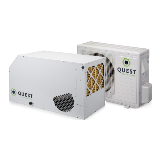
The Quest 185 Cool is a split system dehumidifier with sensible cooling
that is integrated into the heating and cooling system to provide the
ultimate in comfort, health and property protection through:
• Dehumidification
• Sensible Cooling
• Air Filtration
The two-piece design allows the sensible heat load generated from
dehumidifying the room to be released in the outside condensing unit,
thus eliminating the need for additional cooling and reducing air conditioner run time.
HVAC Installer: Please Leave Manual for Homeowner
P/N: 4033180
Sold by:
Specifications subject to change without notice.
Serial No.:
Install Date:
4201 Lien Rd
Madison, WI 53704
www.QuestHydro.com
1
Phone 608-237-8400
Toll-Free 1-877-420-1330
info@QuestHydro.com
TS-961
03/17 Rev. B
Advertisement
Table of Contents

Related Manuals for Therma-Stor Quest 185 Cool


Summary of Contents for Therma-Stor Quest 185 Cool
-
Page 1: Installation Instructions
Installation Instructions INSTALLATION BY A HVAC PROFESSIONAL IS RECOMMENDED The Quest 185 Cool is a split system dehumidifier with sensible cooling that is integrated into the heating and cooling system to provide the ultimate in comfort, health and property protection through: •... -
Page 2: Table Of Contents
TABLE OF CONTENTS Quest 185 Cool Installation, Operation and Maintenance Instructions Safety Instructions ......................3 Specifications ........................4 Optional Accessories ......................5 Dehumidifier Set Up ......................6 Condensing Set Up ......................7 Condensate Removal ......................8 Hanging Install Diagram ....................8 Ducting..........................8 Dehumidifier Electrical Requirements ................9 Condensing Unit Electrical Requirements .............. -
Page 3: Safety Instructions
THIS SYMBOL MEANS IMPORTANT INSTRUCTIONS. FAILURE TO HEED THEM CAN RESULT IN INJURY OR MATERIAL PROPERTY DAMAGE. Registrations The Quest 185 Cool conforms to unified standard UL 474 and CSA Standard C22.2 No. 92. WARNING! 120 VOLTS MAY CAUSE SERIOUS INJURY FROM ELECTRIC SHOCK. DISCONNECT ELECTRICAL POWER BEFORE STARTING INSTALLATION OR SERVICING, AND LEAVE POWER DISCONNECTED UNTIL INSTALLATION OR SERVICE IS COMPLETED. -
Page 4: Specifications
SPECIFICATIONS Quest 185 Cool Installation, Operation and Maintenance Instructions Dehumidifier Part Number: 4037391 20 1/4” Blower: 406 CFM @ 0.0” WG 374 CFM @ 0.2” WG 348 CFM @ 0.4” WG Power: 160 Watts @ 80°F and 60% RH Supply Voltage: 115 VAC –... -
Page 5: Optional Accessories
10" Flex Insulated Duct 25' 4028399 10" Oval to Round Adapter Items Included in Box: • Quest 185 Cool Dehumidifier • Quest 185 Cool Condensing Unit • Quest 185 Cool Installation Instructions • Quest 185 Cool Leveling Feet 1-877-420-1330 www.QuestHydro.com... -
Page 6: Dehumidifier Set Up
DEHUMIDIFIER SET UP Quest 185 Cool Installation, Operation and Maintenance Instructions Important Precautions • The dehumidifier is designed to be installed indoors in a space that is protected from rain and flooding. • Install the dehumidifier with enough space to access the back and side panels for maintenance and service. -
Page 7: Condensing Set Up
CONDENSING UNIT SET UP Quest 185 Cool Installation, Operation and Maintenance Instructions CAUTION! THIS SYSTEM CONTAINS BOTH REFRIGERANT AND OIL. SOME RUBBER ROOFING MATERIAL MAY ABSORB OIL AND CAUSE THE RUBBER TO SWELL WHEN IT COMES INTO CONTACT WITH OIL. THE RUBBER WILL THEN BUBBLE AND COULD CAUSE LEAKS. PROTECT THE ROOF SURFACE TO AVOID EXPOSURE TO REFRIGERANT AND OIL DURING SERVICE AND INSTALLATION. -
Page 8: Condensate Removal
SYSTEM REQUIREMENTS Quest 185 Cool Installation, Operation and Maintenance Instructions Condensate Water Removal Condensate drains by gravity via the drain port. Use 3/4” male NPT PVC pipe. Route drain pipe to drain. Install a trap if possible. Take care when installing drain pipe to drain port. Use an adjustable wrench to secure the drain port. An optional condensate pump kit may be installed if a lift is required to dispose of the condensate. -
Page 9: Dehumidifier Electrical Requirements
Quest offers a variety of control devices for use with the Quest 185 Cool. The control is to be located remotely from the dehumidifier and placed in the space to be conditioned. A low voltage (24 Volt) control MUST be used with the Quest 185 Cool and MUST be connected with low voltage (18-22 gauge) thermostat wire. -
Page 10: Condensing Unit Electrical Requirements
CONDENSING UNIT Quest 185 Cool Installation, Operation and Maintenance Instructions ELECTRICAL REQUIREMENTS The condensing unit requires a dedicated 120Vac 20 Amp circuit capacity. Install a properly sized branch circuit disconnect (20 Amp) within sight of the unit. The Installer must supply the power wiring for the condensing unit. -
Page 11: Condensing Unit & Dehumidifier Wiring
CONDENSING UNIT Quest 185 Cool Installation, Operation and Maintenance Instructions & DEHUMIDIFIER WIRING 24VAC SIGNAL FROM DEHU. 115 VAC LINE NEUTRAL LINE NEUTRAL BLK-3 GRN-4 DEHU. COND. RELAY CAP. VIO-6 BLK-5 BRN-3 RELAY COIL BLOWER RELAY BLK-1 BLOWER BLK-2 CAP. -
Page 12: Line Set Installation
LINE SET INSTALLATION Quest 185 Cool Installation, Operation and Maintenance Instructions Line Set Isolation — The followin The installer must supply a line set (1/4” liquid line, 3/8” gas line) suitable for use with R410a refrigerant to connect the indoor unit REFRIGERANT LINE SET —... - Page 13 LINE SET INSTALLATION Quest 185 Cool Installation, Operation and Maintenance Instructions When installing the line set: • Make sure the lines are suitable for use with R410a. • Do not crush the lines and always allow a minimum bend radius of 2 inches.
-
Page 14: Brazing The Line Set
LINE SET INSTALLATION Quest 185 Cool Installation, Operation and Maintenance Instructions Brazing the Line Set WARNING! POLYOL ESTER (POE) OILS USED WITH HFC-410A REFRIGERANT ABSORB MOISTURE VERY QUICK- LY. IT IS VERY IMPORTANT THAT THE REFRIGERANT SYSTEM BE KEPT CLOSED AS MUCH AS POS- SIBLE. - Page 15 LINE SET INSTALLATION Quest 185 Cool Installation, Operation and Maintenance Instructions CAUTION! THE DEHUMIDIFIER IS SHIPPED FROM THE FACTORY PRESSURIZED WITH A CHARGE OF INERT GAS AND WITH RUBBER PLUGS IN THE LINES. PURGE THE INERT GAS FROM THE DEHUMIDIFIER BY REMOVING THE RUBBER PLUGS IN THE LIQUID AND GAS LINES TO RELEASE THE INERT GAS BEFORE CONNECTING THE LINE SET.
-
Page 16: Leak Test Line Set And Dehumidifier
LINE SET INSTALLATION Quest 185 Cool Installation, Operation and Maintenance Instructions Leak Test Line Set and Dehumidifier Manifold Gage Set When checking the system charge, use a manifold gage set that features low loss anti-blow back fittings. Manifold gage set used with HFC-410A refrigerant systems must be capable of handling the higher system operating pressures. -
Page 17: Evacuating The Line Set And The Dehumidifier
LINE SET INSTALLATION Quest 185 Cool Installation, Operation and Maintenance Instructions Evacuating the Line Set and The Dehumidifier 1. Remove the valve cores from the service ports on the liquid and gas line stubs using no-loss valve core removal tools. -
Page 18: Charging The System
LINE SET INSTALLATION Quest 185 Cool Installation, Operation and Maintenance Instructions Charging the System The condensing unit is pre-charged with 42 oz. of HFC-410A refrigerant. The installer will add HFC-410A refrigerant for the dehumidifier and line set. 1. Calculate the amount of HFC-410A required by determining the length of the line set and performing the calculation below: 11oz + 2.2oz per every 10 feet of line set length = Total charge required... -
Page 19: Controls
The control and the control wires leaving the Quest 185 Cool are numbered and color-coded to prevent confusion. Depending on the control, some of the wires leaving the Quest 185 Cool may not be used. For safety, the uncon- nected wires should be covered with wire nuts. Be sure to consult the electrical schematic in this manual or inside the access panel of the Quest 185 Cool before making control connections. -
Page 20: Controls
CONTROLS Quest 185 Cool Installation, Operation and Maintenance Instructions A low voltage control must be used with the Quest 185 Cool. Five Color Coded Wires Control Operation Green (or brown) Fan control Blue Dehumidification (fan and compressor) control 24 VAC power transformer neutral side (common with white) -
Page 21: Service
Relay Refrigerant Charging WARNING! SERVICING THE QUEST 185 COOL WITH ITS HIGH PRESSURE REFRIGERANT SYSTEM AND HIGH VOLTAGE CIRCUITRY PRESENTS A HEALTH HAZARD WHICH COULD RESULT IN DEATH, SE- RIOUS BODILY INJURY, AND/OR PROPERTY DAMAGE. SERVICE MUST BE PERFORMED BY A QUALIFIED SERVICE TECHNICIAN. -
Page 22: Troubleshooting
SERVICE Quest 185 Cool Installation, Operation and Maintenance Instructions Troubleshooting CAUTION! TROUBLESHOOTING SHOULD BE PERFORMED BY A QUALIFIED HVAC TECHNICIAN. Symptom Possible Reason Troubleshooting Procedure Neither fan nor com- 1. Dehumidifier unplugged or WARNING! pressor no power to outlet. running. - Page 23 SERVICE Quest 185 Cool Installation, Operation and Maintenance Instructions Troubleshooting (Continued) Symptom Possible Reason Troubleshooting Procedure Fan is not running. 1. Loose connection in WARNING! Dehumidification fan circuit. or fan is being called 2. Obstruction prevents fan ELECTRICAL SHOCK HAZARD: for.
- Page 24 SERVICE Quest 185 Cool Installation, Operation and Maintenance Instructions Troubleshooting CAUTION! TROUBLESHOOTING SHOULD BE PERFORMED BY A QUALIFIED HVAC TECHNICIAN. Symptom Possible Reason Troubleshooting Procedure WARNING! ELECTRICAL SHOCK HAZARD: ELECTRICAL POWER MUST BE PRESENT TO PERFORM SOME TESTS. THESE TESTS SHOULD BE PERFORMED BY A QUALIFIED SERVICE PERSON.
-
Page 25: Warranty
Therma-Stor such that Therma-Stor receives such claim prior to the end of the applicable warranty period. Therma-Stor shall have no obligation hereunder with respect to any claim received by Therma-Stor after the expiration of the applicable warranty period. As a further condition to obtaining warranty coverage hereunder, the Customer must present forms of invoices evidencing proof of purchase of a Product. - Page 26 1-877-420-1330 www.questhydro.com...
Need help?
Do you have a question about the Quest 185 Cool and is the answer not in the manual?
Questions and answers