Table of Contents
Advertisement
Quick Links
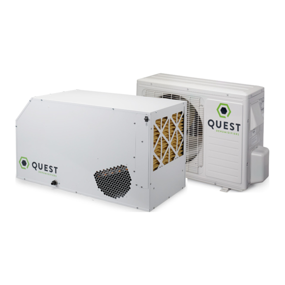
Quest 185 Cool
Quest 185 Cool
Installation, Operation and Maintenance Instructions
Installation, Operation and Maintenance Instructions
– Read and Save These Instructions –
This manual is provided to acquaint you with the
dehumidifier so that installation, operation and
maintenance can proceed successfully. Ultimate
satisfaction depends on the quality of installation and a
thorough understanding of this equipment. The dehumidifier
is built around tested engineering principles and has passed
a thorough inspection for quality of workmanship and
function.
Features:
•
4,300 BTU Cooling
•
Industry-leading efficiency
•
Patented, optimized air-to-air heat exchanger
•
High-efficiency, long-life impeller fan
•
Quiet operation
•
Superior air filtration (MERV-11 standard)
•
Auto-restart after power outages
•
Environmentally friendly R410A refrigerant
•
Low voltage control
INSTALLATION BY A HVAC PROFESSIONAL IS RECOMMENDED
HVAC Installer: Please Leave Manual for Homeowner
P/N: 4033180
Sold by:
1-877-420-1330
Specifications subject to change without notice.
Serial No.:
Installation, Operation and Maintenance Instructions
Water Removal Rates (Pints/Day) @ 80°F 60% (AHAM)
Dehumidifier
185 Cool
Install Date:
4201 Lien Rd
Madison, WI 53704
www.QuestHydro.com
1 1
Pints Removed
Gallons/Liters
184
23.0/87.2
Phone 608-237-8400
Toll-Free 1-877-420-1330
info@QuestHydro.com
TS-961
03/17 Rev. C
Advertisement
Table of Contents

Subscribe to Our Youtube Channel
Related Manuals for Therma-Stor Quest 185 Cool


Summary of Contents for Therma-Stor Quest 185 Cool
- Page 1 Quest 185 Cool Quest 185 Cool Installation, Operation and Maintenance Instructions Installation, Operation and Maintenance Instructions Installation, Operation and Maintenance Instructions – Read and Save These Instructions – This manual is provided to acquaint you with the dehumidifier so that installation, operation and maintenance can proceed successfully.
-
Page 2: Table Of Contents
Quest 185 Cool Installation, Operation and Maintenance Instructions Safety Instructions ......................3 1. Intended Application for Quest 185 Cool Dehumidifier ..........4 2. Registrations ........................4 3. Parts List Included ......................4 4. Specifications .........................4 5. Installation ........................5 5.1 Dehumidifier Setup ....................5 5.1 A Location ...................... -
Page 3: Safety Instructions
Safety Precautions Read the installation, operation and maintenance instructions carefully before installing and operating this device. Proper adherence to these instructions is essential to obtain maximum benefit from your Quest 185 Cool Dehumidifier. READ AND SAVE THESE INSTRUCTIONS • The Dehumidifier portion is designed to be installed INDOORS IN A SPACE THAT IS PROTECTED FROM RAIN AND FLOODING. -
Page 4: Intended Application For Quest 185 Cool Dehumidifier
In order to efficiently control humidity levels, the area in which the dehumidifier is to be operated must be free of water intrusion or excessive fresh (outside) air infiltration. Before installing the Quest 185 Cool Dehumidifier, water intrusion and air infiltration problems should be addressed or noted in calculations. -
Page 5: Installation
Place the Quest 185 Cool Dehumidifier on supports that raise the base of the unit 2.5” above the top of the flanges on the drain pan beneath it. Raising the Quest 185 Cool Dehumidifier will help the unit drain with gravity flow. Do not place the Quest 185 Cool Dehumidifier directly on structural building members without vibration absorbers or unwanted noise may result. -
Page 6: B Electrical Requirements
Be careful not to cross the wires when connecting the Quest 185 Cool Dehumidifier and the remote control panel. The remote controls of the Quest 185 Cool Dehumidifier are powered by a low voltage circuit (24 VAC) and must NEVER contact or be connected to a high voltage circuit. The control terminals and remote control are labeled and numbered to prevent confusion. -
Page 7: D Hanging Diagram
5.1 E Ducting Supply Duct Kit (P/N 4028607) A factory designed supply duct kit can be purchased to accept 10” ducting to both outlets of the Quest 185 Cool. Contact your dealer or call 1-877-420-1330 to order or go to www.questhydro.com/product-category/accessories. -
Page 8: B Electrical Requirements
Quest 185 Cool Installation, Operation and Maintenance Instructions • DO NOT use the condensing unit as a bench or table. • Do not place the condensing unit where the sound and vibration caused by running the unit will a cause a nuisance. -
Page 9: Line Set Installation
Quest 185 Cool Installation, Operation and Maintenance Instructions 5.3 Line Set Installation The installer must supply a line set (1/4” liquid line, 3/8” gas line) suitable for use with R410a refrigerant to connect Line Set Isolation — The following illustrations are examples of proper refrigerant line the indoor unit to the outdoor unit. - Page 10 Quest 185 Cool Installation, Operation and Maintenance Instructions When installing the line set: • Make sure the lines are suitable for use with R410a. • Do not crush the lines and always allow a minimum bend radius of 2 inches.
-
Page 11: Brazing The Line Set
Quest 185 Cool Installation, Operation and Maintenance Instructions 5.4 Brazing the Line Set WARNING! Polyol ester (POE) oils used with HFC-410A refrigerant absorb moisture very quickly. It is very important that the refrigerant system be kept closed as much as possible. Do not remove line set caps or service valve stub caps until you are ready to make connections. - Page 12 Quest 185 Cool Installation, Operation and Maintenance Instructions Use the following procedure to connect the line set to the Dehumidifier: 1. Purge the inert gas from the dehumidifier by removing the rubber plugs in the liquid and gas lines to release the inert gas before connecting the line set.
-
Page 13: Leak Test Line Set And Dehumidifier
Quest 185 Cool Installation, Operation and Maintenance Instructions 5.5 Leak Test Line Set and Dehumidifier Manifold Gage Set When checking the system charge, use a manifold gage set that features low loss anti-blow back fittings. Manifold gage set used with HFC-410A refrigerant systems must be capable of handling the higher system operating pressures. -
Page 14: Evacuating The Line Set And The Dehumidifier
Quest 185 Cool Installation, Operation and Maintenance Instructions 7. Adjust the dry nitrogen pressure regulator to 150 psig. Open the valve on the high pressure side of the manifold gage set to pressurize the line set and dehumidifier. 8. Close the valve on the dry nitrogen cylinder. Close the valve on the high pressure side of the manifold gage set. -
Page 15: Charging The System
Quest 185 Cool Installation, Operation and Maintenance Instructions HIGH OUTDOOR MANIFOLD UNIT GAUGE SET MICRON GAUGE TO VAPOR SERVICE VALVE VACUUM PUMP RECOMMEND MINIMUM 3/8” HOSE TO LIQUID SERVICE VALVE 5.7 Charging the System The condensing unit is pre-charged with 42 oz. of HFC-410A refrigerant. The installer will add HFC-410A refrig- erant for the dehumidifier and line set. -
Page 16: Control Options
RECOMMEND MINIMUM 3/8” HOSE 6. Control Options The Quest 185 Cool Dehumidifier can be controlled by its on board dehumidistat or with an external control using its low voltage terminal block. 6.1 On board dehumidistat The humidity control is an adjustable switch that closes when the relative humidity of the air in which it is located rises to the dial set point. -
Page 17: External Control
• To power a 24V HVAC accessory, connect the accessory to the COM terminal and the 24V terminal. NOTE: 18 ga wire needed between the Quest 185 Cool dehumidifier and the external control Quest offers two external control options 1-877-420-1330 www.QuestHydro.com... -
Page 18: A Deh 3000R
Quest 185 Cool Installation, Operation and Maintenance Instructions 6.2 A DEH 3000R Unit 1 Unit 2 Unit 3 Unit 4 Unit 5 Unit 6 4028531 ONEYWELL REMOTE HUMIDISTAT QUEST DEH 3000R CONTROL WIRING DIAGRAM WIRING DIAGRAM BEFORE TURNING ON UNIT: 1. -
Page 19: Standard Air Filter
To access the air filter, remove the filter access panel from the end of the Quest 185 Cool Dehumidifier. The filter should be readily visible and can be removed by pulling it straight out of the Quest 185 Cool Dehumidifier. -
Page 20: Service Parts List - Condensing Unit
Quest 185 Cool Installation, Operation and Maintenance Instructions 8.4 Service Parts List - Condensing Unit Item Part No. Description 4033211 4033212 Fan-Axial 4033213 Compressor 4033214 Capacitor 4033216 Capacitor-Fan Motor 4033215 Motor 4022484 Relay 8.5 Troubleshooting CAUTION! Troubleshooting should be performed by a qualified HVAC technician. - Page 21 Quest 185 Cool Installation, Operation and Maintenance Instructions Low dehumidification capacity (evaporator is frosted continuously). Dehumidification is being called for. 1. Defrost thermostat loose or defective. 2. Low refrigerant charge. 3. Dirty air filter(s) or air flow restricted. 4. Excessively restrictive ducting connected to unit.
-
Page 22: Wiring Diagrams
Quest 185 Cool Installation, Operation and Maintenance Instructions Troubleshooting Procedure for Performance Related Issues. This method of diagnosis is used to function check the internal components in the dehumidifier. This is to be used when a performance issue is suspected. -
Page 23: Dehumidifier Wiring Diagram
Quest 185 Cool Installation, Operation and Maintenance Instructions 9.2 Condenser Wiring Diagram Condensing Unit Wiring Diagram 24VAC SIGNAL 115 VAC FROM DEHU. LINE NEUTRAL COND. RELAY COIL CAP. COND. RELAY COMPRESSOR BLOWER 4033179 CAP. 9.3 Dehumidifier and Condenser Wiring Diagram 24VAC SIGNAL FROM DEHU. -
Page 24: Optional Accessories
Quest 185 Cool Installation, Operation and Maintenance Instructions 10. Optional Accessories PART NO. DESCRIPTION 4028531 DEH 3000R Control (with remote) 4021475 MERV 11 Filter (16"x20"x2") 4028614 Pump Kit 4036685 Hang Kit 1-877-420-1330 www.QuestHydro.com info@QuestHydro.com... -
Page 25: Warranty
Therma-Stor such that Therma-Stor receives such claim prior to the end of the applicable warranty period. Therma-Stor shall have no obligation hereunder with respect to any claim received by Therma-Stor after the expiration of the applicable warranty period. As a further condition to obtaining warranty coverage hereunder, the Customer must present forms of invoices evidencing proof of purchase of a Product.
Need help?
Do you have a question about the Quest 185 Cool and is the answer not in the manual?
Questions and answers