
Related Manuals for DPS Telecom NetGuardian 832A G5


Summary of Contents for DPS Telecom NetGuardian 832A G5
- Page 1 NetGuardian 832A & 864A G5 USER MANUAL Visit our website at www.dpstelecom.com for the latest PDF manual and FAQs. February 26, 2010 Firmware Version 5.2D D-OC-UM102.26100...
- Page 2 Notice The material in this manual is for information purposes and is subject to change without notice. DPS Telecom shall not be liable for errors contained herein or consequential damages in connection with the furnishing, performance, or use of this...
-
Page 4: Table Of Contents
Contents Visit our website at www.dpstelecom.com for the latest PDF manual and FAQs NetGuardian G5 Overview About This Manual Shipping List Port Allocation Optional Accessories Specifications Hardware Installation Tools Needed Mounting Power Connection LAN Connection Telco Connection Alarm and Control Relay Connections 6.6.1 Alarm and Control Relay Connector Pinout Table (832A) 6.6.2... - Page 5 7.2.1 Sound off 7.2.2 Reboot 7.2.3 Run Config 7.2.4 Contrast Alarm Speaker Front Panel LEDs Back Panel LEDs Configuring the NetGuardian 11.1 RADIUS Authentication (Available as of Firmware 5.0I) Connecting to the NetGuardian 12.1 ... via Craft Port 12.2 ... via LAN TTY Interface 13.1 Unit Configuration...
- Page 6 14.4 Trap SNMP Logic 14.5 ASCII Conversion 14.6 RADIUS Disctionary File (Available on Resource Disk) Frequently Asked Questions 15.1 General FAQs 15.2 SNMP FAQs 15.3 Pager FAQs Technical Support...
-
Page 7: Netguardian G5 Overview
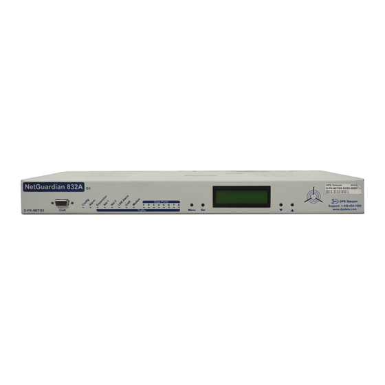
NetGuardian G5 Overview Fig. 1.1. The NetGuardian has all the tools you need to manage your remote site. The NetGuardian G5 — The Intelligent RTU for Complete Site Management The NetGuardian G5 is a RoHS 5/6-compliant, LAN-based, SNMP/DCPx remote telemetry unit. The NetGuardian has all the tools you need to manage your remote sites, including built-in alarm monitoring, paging and email capabilities that can eliminate the need for an alarm master. -
Page 8: About This Manual
While unpacking the NetGuardian, please make sure that all of the following items are included. If some parts are missing, or if you ever need to order new parts, please refer to the part numbers listed and call DPS Telecom at (800) 622-3314. - Page 9 Eight 3/8" Ear Screws Four Standard Rack Screws Four Metric Rack Screws Three 3/4-Amp GMT Main Power Fuses Two Large Power Connector Plugs for Main Power Four Cable Ties (Sixteen with hinged panel) 4 Pin Analog Connector Pads Screws and connectors are packaged in a sealed hardware kit, shown above (Hardware kit containing a WAGO connector) Optional Items Two 1/4-Amp GMT Accessory Fuses...
-
Page 10: Port Allocation
Port Allocation Located on the top of the unit in the back left corner is the Port Allocation Sticker. This sticker includes your part number (D-PK-NETG5-#####.#####), which specifies your build option. The table below it lists your port allocation. Optional Accessories You can extend the capabilities of the NetGuardian through accessory units that provide greater discrete alarm capacity, remote audiovisual alarm notification, visual surveillance of remote sites, and other options. - Page 11 NetGuardian E16 D-PK-DXE16 Adding the NetGuardian E16 provides an additional 16 alarm points and 16 controls. One NetGuardian E16 unit may be used per NetGuardian 832A/864A G5 remote. In this configuration, the E16 must be the last unit in the chain.
- Page 12 Pluggable Barrier Panel For 19" rack: D-PK-NGPAN-12003 For 23" rack: D-PK-NGPAN-12007 The pluggable barrier panel provides screw-lug barrier plug connections for the NetGuardian's alarms and control relays. NetGuardian 3288 Test Fixture D-PK-TSTBX-12005.00001 Every DPS product is rigorously tested before shipping, and the NetGuardian Test Box allows technicians to verify every discrete alarm input, control relay, and voltage-based analog alarm input on a NetGuardian G5.
-
Page 13: Specifications
Specifications Discrete Alarm Inputs: 32 (expandable to 80, 128, or 176 in G5 model) 64 (expandable to 112, 160, or 208 in 864A model) Analog Alarms: Analog Input Range: (–94 to 94 VDC or 4 to 20 mA) Control Relays: 8 Form C (expandable to 16, 24, 32) Maximum Voltage: 60 VDC/120 VAC... -
Page 14: Hardware Installation
Hardware Installation Tools Needed To install the NetGuardian, you'll need the following tools: Phillips No. 2 Screwdriver Small Standard No. 2 Screwdriver Wire Strippers/Cutter Wire Wrap Gun (if hinged wire wrap panel is used) Punch Down Tool (if 66 blocks are used) PC with NGEditG5 software Mounting Fig. -
Page 15: Power Connection
Power Connection Fig. 6.3.1. Power connectors and fuse. The NetGuardian has two screw terminal barrier plug power connectors, located on the left side of the back panel. (See Figure 6.3.1.) The Grounding Lug on the back of the unit provides a permanent connection to earth ground when connected. - Page 16 correctly, the LED by the connector will light GREEN. If the polarity of the power feed is reversed, the LED will not illuminate. 6. Repeat Steps 2–4 for Power Connector B. 7. Reinsert the fuse to power the NetGuardian. The front panel LEDs will flash RED and GREEN. To connect the NetGuardian to a power supply using a WAGO connector, follow these steps: The Grounding Lug on the back of the unit provides a permanent connection to earth ground when connected.
- Page 17 Inserting a -48 VDC Line into Slot 1 of WAGO Connector 5. Push the power connector plug firmly back into the power connector. If the power feed is connected correctly, the LED by the connector will light GREEN. If the polarity of the power feed is reversed, the LED will not illuminate.
-
Page 18: Lan Connection
LAN Connection RJ45 Ethernet Connection Fig. 6.4.1. Two 10/100 Ethernet ports (With Switch) 6 Receive In– (RI–) 3 Receive In + (RI+) 2 Transmit Out– (TO–) 1 Transmit Out + (TO+) Fig. 6.4.3 Ethernet port pinout Fig. 6.4.2. Two 10/100 Ethernet ports (Without Switch) For enhanced security, the NetGuardian G5 has two 10/100 Ethernet ports. -
Page 19: Telco Connection
Telco Connection Fig. 6.5.1. Telco jack The rear panel telco jack (see Figure 6.5.1) connects the NetGuardian internal modem to a standard phone line for dial-up access and pager alarm notification. RJ11 Phone Line Connection 3 Ring 2 Tip Fig. 6.5.2 Telco jack pinout The pinout for the Telco jack is shown in Figure 6.5.2, above. -
Page 20: Alarm And Control Relay Connector Pinout Table (832A)
6.6.1 Alarm and Control Relay Connector Pinout Table (832A) Discretes 1–25 Discretes 25–32 Control Relays 1–8 RTN ALM RTN ALM NO/NC CO ALM 25 CTRL 1 ALM 1 ALM 13 ALM 26 CTRL 2 ALM 2 ALM 14 ALM 27 CTRL 3 ALM 3 ALM 15... -
Page 21: Alarm And Control Relay Connector Pinout Table (864A)
6.6.2 Alarm and Control Relay Connector Pinout Table (864A) Analogs 7-8 Discretes 1–48 Discretes 49-64, Relays 1-8, Analogs 1-6 Relays 1-8 RLY 1 RLY 2 RLY 3 RLY 4 RLY 5 RLY 6 RLY 7 RLY 8 FUSE ADC 1 ADC 2 ADC 3 ADC 4**... -
Page 22: Discretes 1-24 Connector Pinout Diagram (832A)
6.6.3 Discretes 1–24 Connector Pinout Diagram (832A) RTN 1 ALM 1 RTN 2 ALM 2 RTN 3 ALM 3 RTN 4 ALM 4 RTN 5 ALM 5 RTN 6 ALM 6 RTN 7 ALM 7 RTN 8 ALM 8 RTN 9 ALM 9 RTN 10 ALM 10... -
Page 23: Analogs1-6/Discretes 25-32/Relays 1-8 Connector Pinout Diagram (832A)
6.6.4 Analogs1–6/Discretes 25–32/Relays 1–8 Connector Pinout Diagram (832A) RTN 25 ALM 25 RTN 26 ALM 26 RTN 27 ALM 27 RTN 28 ALM 28 RTN 29 ALM 29 RTN 30 ALM 30 RTN 31 ALM 31 RTN 32 ALM 32 CTRL 1 NO CTRL 1 CO CTRL 2 NO... -
Page 24: Discretes 1- 48 Connector Pinout Diagram (864A)
6.6.5 Discretes 1- 48 Connector Pinout Diagram (864A) Fig. 6.6.5.1- Pinout Diagram for Discretes 1-48 Connector RTN* is the alarm return pin. Standard configurations have this pin tied to GND. While it is possible to change this configuration to utilize different types of alarms (i.e. TTL, Open Collector, Battery Closure), the hardware must be ordered in that configuration. -
Page 25: Analogs 1-6/Discretes 49-64/Relays 1-8 Connector Pinout Diagram (864A)
6.6.6 Analogs 1-6/Discretes 49-64/Relays 1-8 Connector Pinout Diagram (864A) Fig. 6.6.5.2- Pinout Diagram for Analogs 1-6/Discretes 49-64/Relays 1-8 Connector RTN* is the alarm return pin. Standard configurations have this pin tied to GND. While it is possible to change this configuration to utilize different types of alarms (i.e. TTL, Open Collector, Battery Closure), the hardware must be ordered in that configuration. -
Page 26: Analog Dipswitches
6.6.7 Analog Dipswitches The analogs are controlled by the dipswitches accessible via the top sliding panel. For milliamp sensor operation (current loop), turn the dipswitch on by placing it in the up (ON) position. For voltage operation, place the dipswitch in the down (OFF) position. You can access the analog dipswitches via the sliding hatch panel on top of the unit WARNING: Do not put the dipswitches in the upward, ON position (current loop mode) unless you are sure of the analog setting. -
Page 27: Integrated Temperature And Battery Sensor (Optional)
6.6.8 Integrated Temperature and Battery Sensor (Optional) Fig. 6.6.6.1. The external temperature sensor The optional integrated temperature and battery sensor monitors the ambient temperature and the NetGuardian's power inputs. This option is available only if it was ordered with your NetGuardian. The integrated temperature sensor measures a range of 32°... - Page 28 Yost RS-232 RJ45 Connector Yost RS-485 RJ45 Connector 8 RTS (Request to Send) 8 TX- (Transmit -) 7 DTR (Data Terminal Ready) 7 N/C (Not Connected) 6 TXD (Transmit Data) 6 RX- (Receive -) 5 GND (Ground) 5 GND (Ground) 4 GND (Ground) 4 GND (Ground) 3 RXD (Receive Data)
-
Page 29: Connecting Netguardian Accessories
6.7.1 Connecting NetGuardian Accessories Some NetGuardian accessories must be connected to particular data ports. However, if you don't use these accessories, the data ports are available for other uses. If you are using a NetGuardian Expansion, connect it to Port 7. 6.7.2 GLD/ECU Expansion Port (RS-485) If you are using a General LCD Display (GLD) unit, connect it to the GLD/ECU port. - Page 30 RJ45 Ethernet Connection 6 Trasmit Out – (TO–) 3 Transmit Out + (TO+) 2 Receive In – (RI–) 1 Receive In + (RI+) Fig. 6.8.2. Regular Ethernet port pinout The four Ethernet ports of the switch are regular straight-through Ethernet ports. (See Figure 6.8.1.) The pinout for the regular Ethernet ports is shown in Figure 6.8.2, above.
-
Page 31: Gsm/Gprs Or Cdma Wireless Modem Top Board (Optional)
(See Figure 6.9.1.) If you ever want to turn off power to the wireless modem, just remove the fuse. You may use any service provider you choose for your wireless connectivity. DPS Telecom has tested and recommends using CrossBridge Solutions. www.crossbridgesolutions.com Phone: (800) 668-4368 Email: info@crossbridgesolutions.com... -
Page 32: Or +24 Vdc Sensor Power Supply
6.10 +12 or +24 VDC Sensor Power Supply Fig. 6.10.1. +12 VDC sensor power supply You can order your NetGuardian G5 with an optional +12 VDC or +24 VDC sensor power supply. (See Figure 6.10.1.) This provides a convenient way to connect an auxiliary sensor to a robust battery power supply. The two-pin connector for the sensor power supply is a barrier plug connector similar to the main power connector. -
Page 33: Optional 66 Block Connector (832A)
6.11 Optional 66 Block Connector (832A) Both of the 50-pin connectors on the back panel of the NetGuardian can be connected to the optional 25-pair 66 Block Connector (part number D-PR-966-10A-00). For 66 block pinout and color code information, see Figure 6.11.1 for Discretes 1–24 and Figure 6.11.2. - Page 34 Fig. 6.11.2. Optional 66 block pinout for Analogs 1–8/Discretes 25–32/Relays 1–8...
-
Page 35: Optional 66 Block Connector (864A)
6.12 Optional 66 Block Connector (864A) Both of the 50-pin connectors on the back panel of the NetGuardian can be connected to the optional 66 block, 25 pair block (part number D-PR-966-10A-00). See Figure 6.12.1 for pinout and color code information for Discretes 1–48 and Figure 6.12.2 for pinouts and color code information for Discretes 49–64, Relays 1–8, and Analogs 1–6. - Page 36 Fig. 6.12.2. 66 Block connections for Discretes 49–64, Relays 1–8, and Analogs 1–6 RTN* is the alarm return pin. Alarms on standard units are dry closure or ground closure. Most units will have RTN internally tied to GND. However, special hardware assemblies may have RTN isolated from GND.
-
Page 37: Optional Hinged Wire-Wrap Back Panel
6.13 Optional Hinged Wire-Wrap Back Panel Turn the plastic swivel to the vertical position to lock in place Fig. 6.13.1. The hinged wire-wrap back panel is mounted on the mounting rack of the NetGuardian Alarm Pinout for NG864 is different than the NG832 and is not compatible with NG832 hinged panel termination units WARNING The optional hinged wire-wrap back panel provides wire-wrap connections for the NetGuardian's alarms and... -
Page 38: Lexan Wire-Wrap Cover
Analogs 1 - 8 Discretes 31 - 32 (Return 31 - 32) Controls 1 - 8 Fig. 6.13.3. Wire-wrap pinouts for Discretes 31–32, Analogs 1–8, and Controls 1–8 6.13.1 Lexan Wire-Wrap Cover Spacer Lexan panel Lexan panel bracket Securing screw Fig. -
Page 39: Optional Hinged Pluggable Back Panel
6.14 Optional Hinged Pluggable Back Panel Fig.6.14.1 - Silk screen on the Hinged Pluggable Back Panel indicates which way to turn the black swivel to lock and unlock the gate. Instructions for installing the Hinged Pluggable Back Panel: Rear View 1. - Page 40 5. Attached the left side of the hinged panel to the rack 6. Unlock the back panel by turning the black with the screws provided. swivel to the horizontal position. (See Figure 6.14.1) Plug the amphenol cables in to the hinged back panel and secure them with the Velcro straps.
-
Page 41: Controls
6.15 Controls Fig. 6.14.1. Adjustable jumpers on the NetGuardian circuit board The following options are adjusted by resetting jumpers on the NetGuardian's circuit board: · Control relays can be switched from normally open (N/O) to normally closed (N/C) To simply configure the jumpers, use the hatch panel access on the top of the NetGuardian chassis. This allows for easy access and configuration of jumpers without having to open the entire case. -
Page 42: Lcd Display
Fig. 6.14.2. Jumper settings for analog alarm inputs and control relays For control relay jumpers, the open position corresponds to normally open operation, and the closed position corresponds to normally closed operation. See Figure 6.14.2. Note: Default settings may be different if you ordered a special configuration NetGuardian. LCD Display Fig. -
Page 43: Alarm And Control Status Messages
Alarm and Control Status Messages If an alarm or control relay is active, the LCD will display the following messages to indicate alarm and control status: The LCD panel will display the following messages to indicate alarm and control status: Discrete Alarms: If there are any standing discrete alarms, the display will read "Discrete Alarms:", followed by the user-defined descriptions of the standing alarm points. -
Page 44: Sound Off
7.2.1 Sound off Fig. 7.3.1.1. Sound Off command Sound off The Sound off command suppresses sounds from the alarm speaker for a user-defined period of 10, 20, or 30 minutes. To scroll to the next menu command, press the q button. To change the Sound off setting, press Sel to select the command. -
Page 45: Run Config
7.2.3 Run Config Fig. 7.3.3.1. Run Config command Run Config The Run Config command forces the TTY configuration interface to run over the craft port at the user defined baud rate (default is 9600 baud). To scroll to the next menu command, press the q button. To run the TTY configuration utility, press Sel. -
Page 46: Front Panel Leds
Front Panel LEDs Fig. 9.1. Front panel LEDs The NetGuardian's front panel LEDs indicate communication and alarm reporting status. LED status messages are described below in Table 9.A. Status Description Blink Green Valid Configuration Config Blink Red Invalid Configuration Blink Red New COS alarm* Alarm Solid Red... -
Page 47: Back Panel Leds
Back Panel LEDs Fig. 10.1. Back panel LEDs for Power (left) and Ethernet connections The back panel LEDs indicate the status of power and Ethernet connections. LED status messages are described below in Table 10.A. Status Description Solid Green Polarity is correct on power feed A Power A and/or B Power... -
Page 48: Radius Authentication (Available As Of Firmware 5.0I)
11.1 RADIUS Authentication (Available as of Firmware 5.0I) RADIUS authentication is now supported by any NetGuardian G5 platform (832A or 864A, with or without hardware acceleration). RADIUS (Remote Authentication Dial In User Service) is an industry-standard way to manage logins to many different types of equipment in one central location. -
Page 49: Via Lan
12.2 ... via LAN Fig. 3.2.1. Ethernet port 1 You can also connect to the NetGuardian over a LAN connection. This is a very convenient way to provision multiple NetGuardian units at multiple locations. Note: You don't have to be connected to a NetGuardian unit to use NGEditG5. -
Page 50: Tty Interface
TTY Interface Fig. 13.1. The TTY interface initial configuration screen The TTY interface is the NetGuardian's built-in provision controls for basic configuration of the NetGuardian. Configure the NetGuardian's ethernet port settings, monitor the status of base and system alarms, operate control relays, view live ping targets , view debug or create proxy connections to other ports. - Page 51 Fig. 13.1.1. Configure the Ethernet port parameters 1. Connect using Hyperterminal @ 9600, 8, N, 1. 2. Type "dpscfg" and hit enter (you won't be able to see this text), the NetGuardian will respond with "Password." Note: If you receive no password prompt then check the port you are using on your PC and make sure you are using a straight thru cable.
-
Page 52: Sfp Fiber Connection (For Fiber Build Option)
3. Type the default password, "dpstelecom," then press Enter. Note: DPS strongly recommends changing the default password. 4. The NetGuardian's main menu will appear. 5. Type C for the C)onfig menu. 6. Type E for E)dit menu. 7. Type E for port settings, 1 for Net 1 and 2 for Net 2. 8. -
Page 53: Edit Ppp Port
13.1.3 Edit PPP Port Choose P)PP to edit your PPP port in TTY Interface. You can choose a baud rate, depending on what device has been chose for the PPP port. Fig. 13.1.3 Edit your PPP port If you are using a modem for the PPP port, then choose mo(D)em for the modem option to define the modem initialization strings. -
Page 54: Tune 202 Modem
13.1.4 Tune 202 Modem Tuning the 202 modem on a NetGuardian G5 can only be done from the TTY interface (using either HyperTerminal through the front craft port or by telnet to the unit over LAN on port 2002). Fig. 13.1.4. Press 'T' to tune the 202 Modem with the TTY interface Though no menu options will appear, use the following commands to tune the 202 modem. -
Page 55: Radius Configuration
13.1.5 RADIUS Configuration The TTY interface can also be used to configure RADIUS settings. After entering the IPA for the RADIUS server, users will be prompted for both a username and password to logon to the unit. This username and password combination will be verified against the RADIUS database, and not the local database. -
Page 56: New! - Tty Command Mode
13.1.6 New! - TTY Command Mode This command line mode offers an alternate way of configuring the NetGuardian G5. This interface is scriptable, and is recommended for advanced users. Entries are NOT case sensitive. Fig. 13.1.6 To enter Command Line mode, login to the TTY, then press Ctrl+C. Tips for using TTY Command Mode ·... - Page 57 , crft,cap,ecu,sps8} # of NetGuardian {get,set} ngddx {0...3} Expanders # of GLD or BSU {get,set} gld {0...16} Timed Tick Period {get,set} timed tick {0...60} {min} System Name {get,set} name string {0..31} chars System Location {get,set} location string {0..31} chars System Contact {get,set} contact string {0..31} chars System Phone...
- Page 58 0=Normal Analog Polarity {get,set} alg {1...8} polarity 1=Reversed Analog Group Number {get,set} alg {1...8} group {mju,mnu, mno,mjo} {1...8} Analog Reference 1 VDC {get,set} alg {1...8} ref1 Number Analog Reference 1 {get,set} alg {1...8} disp1 Number Display Analog Reference 2 VDC {get,set} alg {1...8} ref2 Number Analog Reference 2...
-
Page 59: Monitoring
13.2 Monitoring 13.2.1 Monitoring the NetGuardian Connect a PC running VT100 terminal emulation software to the craft port or connect via LAN using a Telnet client with VT100 emulation to port 2002 to reach the monitor menu selection. This section allows you to do full system monitoring of the NetGuardian including: all alarms, ping information, relays, analogs, and system status. -
Page 60: Monitoring Ping Targets
Fig. 13.3.1.1.1. This example shows page two of the discrete alarms 13.2.1.2 Monitoring Ping Targets View the status of all your ping targets from the M)onitor menu > P)ing targets option. This screen displays the ping target ID, description, and IP address. Under Status the word Alarm will appear if an alarm has been activated and Clear will appear if an alarm condition is not present. -
Page 61: Monitoring And Operating Relays (Controls)
13.2.1.3 Monitoring and Operating Relays (Controls) The NetGuardian comes equipped with 8 relays that can be used to control external devices. Monitor the status of your relays from the M)onitor menu > R)elays option. Relays are set to normally open (N/O) as the factory default, but each or all of them can be changed to normally closed (N/C) by changing their respective jumper (see Section 6.12, "Jumper Options"). -
Page 62: Monitoring System Alarms
13.2.1.5 Monitoring System Alarms View the status of the NetGuardian's system alarms from the M)onitor menu > S)ystem option. Under Status, the word Alarm will appear if an alarm has been activated and Clear will appear if an alarm condition is not present. -
Page 63: Viewing Live Target Pings
Fig. 13.3.1.7.1. Monitor and reset the Accumulator Timer Field Description Display and Point Indicates which alarm point is to be monitored. Reference Point Description The user-defined description of the monitored alarm point. The current status of the monitored point. Point Status Amount of time allowed to accumulate before the system alarm, Event Threshold “Accumulation Event”... -
Page 64: Event Logging
Fig. 13.3.3.1. Access devices connected to the eight data ports on the back panel through M)onitor menu > P)roxy option 13.2.4 Event Logging Choose E)vent log to view the up to 100 events posted to the NetGuardian; including power up, base and system alarms, ping alarms, analog alarms, and controls. -
Page 65: Backing Up Netguardian Configuration Data Via Ftp
Event Log Field Description Event number (1–100) Date Date the event occurred Time Time the event occurred Alarm Group State State of the event (A=alarm, C=clear) PRef Point reference (See Appendix A for display descriptions). User defined description of the event as entered in the alarm point Description and relay description fields. -
Page 66: Debug Input And Filter Options
13.2.6 Debug Input and Filter Options Debug Input Options Exit Debug Show BAC status points Show task status Show DUART information Show network routing table Clear debug enable bitmap. Turn all debug filters OFF Display Options Debug Filter Options: (1) Alarm toggle switch. Shows posting of alarm data (2) Analog toggle switch. -
Page 67: Reference Section
Reference Section 14.1 Display Mapping Port Address Display Description Clear Discrete Alarms 1-32 8001-8032 9001-9032 For NG 864 Alarms 1-64 8001-8064 9001-9064 Ping Table 8065-8096 9065-9096 Analog Channel 1** 8129-8132 9129-9132 Analog Channel 2** 8193-8196 9193-9196 Analog Channel 3** 8257-8260 9257-9260 Analog Channel 4** 8321-8324... - Page 68 SNMP Trap #s Points Description Clear Relays 8641 9641 Relays 8642 9642 Relays 8643 9643 Relays 8644 9644 Relays 8645 9645 Relays 8646 9646 Relays 8647 9647 Relays 8648 9648 Timed Tick 8657 9657 Exp. Module Callout 8658 9658 Network Time Server 8659 9659 Accumulation Event...
-
Page 69: System Alarms Display Map
Note: See Section 14.1.1, "System Alarms Display Map," for detailed descriptions of the NetGuardian's system alarms. 14.1.1 System Alarms Display Map Display Points Alarm Point Description Solution Toggles state at constant rate as To turn the feature off, set the Timed configured by the Timed Tick timer Timed Tick variable. - Page 70 Display Points Alarm Point Description Solution If DCP responder is not being used, then set the DCP Unit ID to 0. The unit has not seen a poll from the Otherwise, try increasing the DCP DCP Poller Master for the time specified by the timer setting under timers, or check Inactive DCP Timer setting.
- Page 71 Display Points Alarm Point Description Solution NetGuardian NGDdx 1 Fail (Expansion shelf 1 Under Ports > Options, verify the number of configured NGDdx units. DX 1 fail communication link failure) Use EXP filter debug and port LEDs to NetGuardian NGDdx 2 Fail (Expansion shelf 2 help diagnose the problem.
-
Page 72: Snmp Manager Functions
14.2 SNMP Manager Functions The SNMP Manager allows the user to view alarm status, set date/time, issue controls, and perform a resync. The display and tables below outline the MIB object identifiers. Table B.1 begins with dpsRTU; however, the MIB object identifier tree has several levels above it. - Page 73 Description Port Address Display Points Discrete Alarms 1-32 Disp 1 Undefined** 33-64 Ping Targets 1-32 Disp 2 Undefined** 33-64 Analog 1 Disp 3 Undefined** 5-64 Analog 2 Disp 4 Undefined** 5-64 Analog 3 Disp 5 Undefined** 5-64 Analog 4 Disp 6 Undefined** 5-64 Analog 5...
-
Page 74: Snmp Granular Trap Packets
NGDdx 1-3 fail 56-58 GLD/BSU 1-3 fail 59-61 CHAN timeout CRFT timeout Table 14.2.A. Alarm Point Descriptions * "No data" indicates that the alarm point is defined but there is no description entered. ** "Undefined" indicates that the alarm point is not used. 14.3 SNMP Granular Trap Packets Tables 14.3.A and 14.3.B provide a list of the information contained in the SNMP Trap packets sent by the... - Page 75 SNMP Header Description Version Public Request Trap Request 1.3.6.1.4.1.2682.1.4 Enterprise 126.10.230.181 Agent address Enterprise Specific Generic Trap 8001 Specific Trap 617077 Time stamp 1.3.7.1.2.1.1.1.0 Object NetGuardian 216 v1.0K Value 1.3.6.1.2.1.1.6.0 Object 1-800-622-3314 Value 1.3.6.1.4.1.2682.1.4.4.1.0 Object 01-02-1995 05:08:27.760 Value 1.3.6.1.4.1.2682.1.4.5.1.1.99.1.1.1 Object Value 1.3.6.1.4.1.2682.1.4.5.1.2.99.1.1.1 Object...
-
Page 76: Trap Snmp Logic
14.4 Trap SNMP Logic NET1 NET2 Trap Dest. Result Subnet 1 & Gateway Not Defined Subnet 3 Trap goes out NET1's Gateway Subnet 1 & Gateway Subnet 2, No Gateway Subnet 3 Trap goes out NET1's Gateway Subnet 1 & Gateway Subnet 2 &... -
Page 77: Radius Disctionary File (Available On Resource Disk)
14.6 RADIUS Disctionary File (Available on Resource Disk) # -*- text -*- # dictionary.dps DPS Telecom, Inc For assistance or support, please contact support@dpstele.com v1.0 Released - 1/23/09 (CBH/DPS) VENDOR 2682 # Standard attribute for NetGuardian RTU. # All values are integer with 1 = True, 0 = False. -
Page 78: Frequently Asked Questions
Frequently Asked Questions Here are answers to some common questions from NetGuardian users. The latest FAQs can be found on the NetGuardian support web page, http://www.dpstelecom.com. If you have a question about the NetGuardian, please call us at (559) 454-1600 or e-mail us at support@dpstele.com 15.1 General FAQs... - Page 79 NetGuardian's NVRAM so they will be saved when the unit is rebooted. Q. The LAN link LED is green on my NetGuardian, but I can't poll it from my T/Mon. A. Some routers will not forward packets to an IP address until the MAC address of the destination device has been registered on the router's Address Resolution Protocol (ARP) table.
- Page 80 Q. How do I back up my NetGuardian configuration? A. There are two ways to back up NetGuardian configuration files: Use NGEditG5 NGEditG5 can read the configuration of a NetGuardian unit connected to your PC via LAN, modem or COM port.
-
Page 81: Snmp Faqs
The T/MonXM variables are included in the distributed MIB only to provide SNMP managers with a single MIB for all DPS Telecom products. Q. How many traps are triggered when a single point is set or cleared? The MIB defines traps like "major alarm set/cleared,"... -
Page 82: Pager Faqs
15.3 Pager FAQs Q. Why won't my alpha pager work? A. To configure the NetGuardian to send alarm notifications to an alpha pager, enter the data phone number for your pager in the Phone Number field. This phone number should connect to your pager service's modem. Then enter the PIN for your pager in the PIN/Rcpt/Port field. -
Page 83: Technical Support
Please have your user manual and hardware serial number ready. 3. Have access to troubled equipment. Please be at or near your equipment when you call DPS Telecom Technical Support. This will help us solve your problem more efficiently. 4. Call during Customer Support hours. - Page 84 “Dependable, Powerful Solutions that allow users to monitor larger, more complicated networks with a smaller, less trained staff” “Your Partners in Network Alarm Management” www.dpstelecom.com 4955 E Yale • Fresno, CA 93727 559-454-1600 • 800-622-3314 • 559-454-1688 fax...
Need help?
Do you have a question about the NetGuardian 832A G5 and is the answer not in the manual?
Questions and answers