
Related Manuals for DPS Telecom NetGuardian LPG D-PK-NGLPG


Summary of Contents for DPS Telecom NetGuardian LPG D-PK-NGLPG
- Page 1 NetGuardian LPG Controller USER MANUAL D-PK-NGLPG Visit our website at www.dpstelecom.com for the latest PDF manual and FAQs. February 15, 2019 D-UM-NGLPG Firmware Version 1.0A...
- Page 2 Notice The material in this manual is for information purposes and is subject to change without notice. DPS Telecom shall not be liable for errors contained herein or consequential damages in connection with the furnishing, performance, or use of this...
-
Page 3: Table Of Contents
Contents Visit our w ebsite at w w w .dpstelecom .com for the latest PDF m anual and FAQs NetGuardian LPG Controller Overview Specifications Shipping List Optional Shipping Items - Available by Request Installation Tools Needed Mounting NetGuardian LPG Controller Front Panel NetGuardian LPG Controller Back Panel Power Connection Valve Controls... - Page 4 10.13 System Alarms 10.14 Timers 10.15 Date and Time Monitoring via the Web Browser 11.1 LPG Automation 11.2 Alarms 11.3 Controls 11.4 Sensors 11.5 User Analogs 11.6 Ping Targets 11.7 System Alarms 11.8 Graph Device Access Descriptions Backup Configuration Firmware Upgrade Reference Section 15.1 Display Mapping...
-
Page 5: Netguardian Lpg Controller Overview
NetGuardian LPG Controller Overview The NetGuardian LPG Controller Meet the NetGuardian LPG Controller The NetGuardian LPG Controller is ideal for remotely managing up to 4 liquid propane tanks. The LPG Controller analyzes the propane flow from each tank to achieve a balanced consumption of propane from all tanks assigned to the automation process. -
Page 6: Specifications
· Compatible with Rochester gauges. · One discrete input for monitoring generator run. · Supports HTTP and HTTPS, Email, SNMP v1, v2 and v3 notifications. · Web configurable. Specifications Hardware Dimensions: 1.720” H x 17.026” W x 7.336” D Mounting: 19”... - Page 7 3 Current measured at rated voltage with all controls latched and all alarms triggered. 4 See analog section in manual for detailed analog accuracy breakdown. * This equipment has been tested and found to comply with the limits for a Class A digital device, pursuant to part 15 of the FCC Rules. These limits are designed to provide reasonable protection against harmful interference when the equipment is operated in a commercial environment.
-
Page 8: Shipping List
Please make sure all of the following items are included with your NetGuardian LPG Controller. If parts are missing, or if you ever need to order new parts, please refer to the part numbers listed and call DPS Telecom at 1-800-622- 3314. - Page 9 3 Point Locking Terminal 2 Point Locking Terminal 2-821-10335-00 2-821-10235-00 Lg. Power Connector (Main Pwr) 2-820-00862-02...
-
Page 10: Optional Shipping Items - Available By Request
Two Standard Rack Screws Pads 1-000-12500-06 2-015-00030-00 14ft. Ethernet Cable D-PR-932-10B-14 Optional Shipping Items - Available by Request Temp Sensor Temp/Humidity Sensor D-PK-DSNSR-12001 D-PK-DSNSR-12002 Small WAGO connector 2-802-01020-00... -
Page 11: Installation
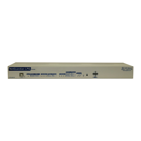
Installation Tools Needed To install the NetGuardian LPG Controller, you'll need the following tools: Phillips No. 2 Screwdriver Small Standard No. 2 Screwdriver PC with terminal emulator, such as HyperTerminal Mounting The NetGuardian LPG Controller can be flush or rear-mounted The NetGuardian LPG Controller mounts in a 19"... - Page 12 Solid Red Blown Fuse Fuse OK Alarm Demand Clear Green Latched Running Released Solid Green Processor has power Power (Lamp) Processor does not have power Blinking Green Data Transmitted over USB Craft Blinking Red Data Received over USB Solid Green LAN Connected LAN Not Connected Flashing Yellow...
-
Page 13: Netguardian Lpg Controller Back Panel
NetGuardian LPG Controller Back Panel The Back Pane l of the Ne tGuardian LPG Controlle r Power Connection The NetGuardian LPG Controller uses a single power input, powered through one barrier plug power connector. NetGuardian LPG Controller Power Terminals and Fuses To connect the NetGuardian LPG Controller to a power supply: 1. -
Page 14: Valve Controls
Valve Controls Valve Controls on the Ne tGuardian LPG Controlle r The 5 AMP GMT fuse powers the control outputs. These valve controls operate the valves on each of the 4 propane tanks. Tank Level Sensors The Tank Le ve l Se nsor Inputs on the Ne tGuardian LPG Controlle r. The Tank Level Sensor inputs monitor the fuel levels in the tanks. -
Page 15: Quick Start: How To Connect To The Netguardian Lpg Controller
Quick Start: How to Connect to the NetGuardian LPG Controller Most NetGuardian LPG Controller users find it easiest to give the unit an IP address, subnet and gateway through the front craft port (TTY interface) to start. Once these settings are saved and you reboot the unit, you can access it over LAN to do the rest of your databasing via the Web Browser interface. - Page 16 2. Select "Install from a list or specific location (Advanced)" 3. Click "Next >" 4. Select "Search for the best driver in these locations." 5. Insert NetGuardian LPG Controller Resource Disc (CD) into your PC. 6. Click "Browse"...
- Page 17 7. Select the "Driver" folder of your NetGuardian LPG Controller Resource Disc Disc (CD) and click "OK" The following message will confirm installation of a new "USB Communications Port" 8. Click "Finish" to close the Wizard. Now that the driver has been installed, a new COM port is being emulated on your PC. Before using hyperterminal, you must confirm the identity of that new COM port (COM1, COM2, COM3...) in the Windows Device Manager.
- Page 18 9. Right-click the "My Computer" icon on your desktop, then click "Manage" 10.Click "Device Manager" in the left pane.
- Page 19 11.Expand the "Ports (COM & LPT)" section in the right pane. Look for "USB Communications Port (COMx)". Note the number of the COM port ("COM3" in the example above). 12.Click on the Start menu > select Programs > Accessories > Communications > HyperTerminal. 13.
- Page 20 • Stop bits: 1 PC and make sure you are using the cable provided. • Flow control: None Additional cables can be ordered from DPS Telecom. Once connected, you will see a blank, white HyperTerminal screen. Press Enter to activate the configuration menu.
- Page 21 ...via LAN NetGuardian LPG Controller Ethernet Port To connect to the NetGuardian LPG Controller via LAN, all you need is the unit's IP address (Default IP address is 192.168.1.100). If you DON'T have LAN, but DO have physical access to the NetGuardian LPG Controller, connect using a LAN crossover cable.
-
Page 22: Tty Interface
TTY Interface The TTY interface is the NetGuardian LPG Controller's built-in interface for basic configuration. From the TTY interface, you can: · Edit the IPA, subnet, and gateway · Set DCP info for T/Mon polling · Configure primary port · Ping other devices on the network ·... -
Page 23: Configure Serial Port Via Tty
Configure Serial Port via TTY Serial port configuration 1. To enter configuration setting for the Serial Port, login to the TTY interface and press C)onfig > s(E)rial. 2. Press the hot keys to toggle through the following options. (* Indicates default settings:) NOTE: Default settings may not reflect the primary interface that shipped in the unit. -
Page 24: How To Send Email Notifications
How to Send Email Notifications 1. Click on the Notifications button in the Provisioning menu. You can setup as many as 8 different notifications. Begin the setup "wizard" by clicking Edit for a notification number. In this example, we'll setup Notification 1 to send emails. - Page 25 4. At the Schedule screen, you'll select the exact days/times you want to receive email notifications. You can set 2 schedules per notification. For example, you may want to receive notifications at certain times during the week, and at different hours on the weekend. Use the check boxes to select the days of the week, and select the time from the drop down menus.
-
Page 26: How To Send Snmp Traps
How to Send SNMP Traps 1. Click on the SNMP button in the Provisioning menu. Enter the SNMP GET and SNMP SET community strings for your network, then click Save. The typical SNMP SET and GET community strings for network devices is "public". - Page 27 4. At the SNMP Notification screen, you'll enter your network's SNMP settings. Enter the IP address of your SNMP Trap Server. Enter the Trap Port Number (usually 162) and the Trap Community password. Click Save and Next. 5. At the Schedule screen, you'll select the exact days/times you want to receive SNMP notifications. You can set 2 schedules per notification.
-
Page 28: Provisioning Menu Field Descriptions
Provisioning Menu Field Descriptions NetGuardian LPG Controller configuration is performed from the Provisioning menus, the menu options in green on the left-side of the web interface. The following pages provide a brief description of the options available in each menu. Saving Configuration Changes to the NetGuardian LPG Controller: At the bottom of each screen you access from the Provisioning Menu, you will see a Save button. -
Page 29: System
10.1 System From the Provisioning > System menu, you will configure and edit the global system, call, T/Mon and control settings for the NetGuardian LPG Controller. The Provisioning > System menu Global System Settings Name A name for this NetGuardian LPG Controller unit. {Optional field) Location The location of this NetGuardian LPG Controller unit. -
Page 30: User Profiles
10.2 User Profiles Clicking User Profiles gives you access to modify the default username and password, and to edit the administrator profile and create up to 9 additional unique user profiles, each with different access rights to the NetGuardian LPG Controller's web interface. -
Page 31: Ethernet
10.3 Ethernet The Edit > Ethernet menu allows you to define and configure Ethernet settings. The Provisioning > Ethernet menu Ethernet Settings MAC Address Hardware address of the NetGuardian LPG Controller. (Not editable - For reference only.) Used only for web browsing. Example: If you don't want to remember this NetGuardian LPG Controller's IP address, you can type in a name is this field, such as Host Name "MyNetGuardian LPG Controller". -
Page 32: Radius
10.4 RADIUS The Provisioning > RADIUS menu allows you to define and configure the RADIUS settings. RADIUS Menu Global Settings How many times the RADIUS server will retry a logon Retry attempt. Enter in the number of seconds before a logon request is Time-out timed out. -
Page 33: Snmp
10.5 SNMP The Provisioning > SNMP menu allows you to define and configure the SNMP settings. SNMP Menu Global Settings Get Community Community name for SNMP requests. Set Community Community name for SNMP SET requests. This field defines how the NetGuardian LPG Controller unit may be accessed via SNMP. This can be set to the following: Read and Write ·... -
Page 34: Notifications
10.6 Notifications From the initial Provisioning > Notifications menu, you will see which of the 8 notifications are enabled, their server, and schedule. Click on the Edit link for one of the notifications to begin configuration. Once you've chosen which notification you want to setup, check the Enable Notification to turn it "on." Then choose a notification method, either email, or SNMP. -
Page 35: 10.6.2 Schedule
SNMP Notification Fields Editing SNMP notification settings SNMP Notification SNMP Trap Server IP The SNMP trap manager's IP address. The SNMP port (UDP port) set by the SNMP trap manager to receive Trap Port No. traps, usually set to 162. Trap Community Community name for SNMP TRAP requests. -
Page 36: Lpg Settings
10.7 LPG Settings This selection provides a look into the Tank Level Automation settings. The Analog settings and Control settings are pulled into one easy-to-configure layout. LPG Automation Settings When checked, enables automation process to open or close the tank valves. Enable Automation Number of tanks that the automation process will analyze. -
Page 37: Alarms
automation process will operate the valves to balance levels across all tanks. When a tank level reaches this threshold, the automation process will open the valve LPG Empty Threshold for that tank. Source for temperature reading. LPG Temperature Source Temperature reading threshold point that we follow to open all valves. Open all Valves on LPG Valve Control Settings ID number of the tank valve. - Page 38 The Provisioning > Alarms menu Basic Alarm Configuration Alarm ID number. Description User-definable description for the discrete alarm point. Reverse: Check this box to reverse the polarity of the alarm point. Leaving this option Rev (Reverse) un-checked means a normally open contact closure is an alarm. When polarity is reversed, a normally closed alarm point is clear when closed.
-
Page 39: Controls
10.9 Controls The NetGuardian LPG Controller's 5 control relays can be configured in the Provisioning > Controls menu. You can enter your own description for these relays and designate them to a notification device(s). The Provisioning > Controls screen Basic Controls Configuration ID number for the control relay. -
Page 40: User Analogs
10.10 User Analogs The NetGuardian LPG Controller's 4 analog inputs measure continuous ranges of voltage. Analog alarms are typically used to monitor propane tank level readings. To configure a user analog, simply fill in your description, thresholds, and other fields listed in the table below, then click Save. Note: An analog channel must be enabled for it to be analyzed by the automation process. - Page 41 Low ref and High Ref The low and high values for scaling voltage to your display units. MjU (Major Under) Threshold settings that, when crossed, will prompt the NetGuardian to set an alarm. MnU (Minor Under) Recorded values less than an under value or greater than an over value will cause alarms. MnO (Minor Over) MjO (Major Over) Select the threshold alarms to post.
-
Page 42: Sensors
10.11 Sensors D-Wire Sensors The NetGuardian LPG Controller supports up to 16 daisy-chained D-Wire sensors via its D-Wire input. Sensors connected to the NetGuardian LPG Controller will appear on the web interface. The background color of the ROM field informs the user of the sensor's configuration state. Also the NetGuardian LPG Controller's first D-Wire sensor used to monitor the internal temperature. - Page 43 Blue - The sensor is not supported by the NetGuardian LPG Controller. To reconfigure or disable the Sensor ID, simply delete any data in this field and click Save. The unit will refresh the sensor ID on that channel. Description User-definable description for the sensor channel.
- Page 44 Valid data types: d Discrete Input a Analog Channel r Relay State n Sensor v Positive Integer Constant s System Alarm Valid operations: + Addition - Subtraction * Multiplication / Division > Greater than < Less than | Conditional Halt 1.
-
Page 45: Ping Targets
10.12 Ping Targets The Provisioning > Ping Targets menu allows you to configure the Description, IP Address, and Notification Devices for each of your ping targets. The Provisioning > Ping Targets menu Provisioning Ping Targets ID number for the ping target. Enab Check this box to enable the ping target. -
Page 46: System Alarms
10.13 System Alarms See "Display Mapping" in the Reference Section for a complete description of system alarms. The Provisioning > System Alarms menu Editing System Alarms Pnt (Point) The system alarm point number Description Non-editable description for this System (housekeeping) Alarm. Silence Check this box to choose to silence this alarm. -
Page 47: Timers
10.14 Timers Enter the amount of time in seconds (sec) or minutes (m), in each value field and click Save. The Provisioning > Timers menu... -
Page 48: Date And Time
10.15 Date and Time The Provisioning > Date and Time menu Unit Time Date Set today's date. Time Set the current time. Automatic Time Adjustment (NTP) Enable NTP Check this box to enable Network Time Protocol. Enter the NTP server's IP address or host name, then click Sync. NTP Server Address or Host Name Example: us.pool.ntp.org. -
Page 49: Monitoring Via The Web Browser
Monitoring via the Web Browser 11.1 LPG Automation This selection provides a look into the Tank Level Automation process. The Analog descriptions, control states and Analog readings are pulled into one easy to read layout. Note that Valve State "Open" means the control is Latched. -
Page 50: Controls
11.3 Controls Use the following rules to operate the NetGuardian LPG Controller's control: Select Controls from the Monitor menu. 2. Under the State field, you can see the current condition of the control. 3. To issue the control, click on a command (OPR - operate, RLS - release, or MOM - momentary) Note: If Automation is enabled, then Valve Control commands will be disabled. -
Page 51: Sensors
11.4 Sensors This selection provides the status of the system's analog channels by indicating if an alarm has been triggered. The Monitor > Sensors screen provides a description of each analog channel, the current reading, the units being read, and alarm conditions (major under, minor under, major over, minor over) according to your temperature settings. If configured under Provisioning >... -
Page 52: User Analogs
11.5 User Analogs On the Monitor > User Analogs menu, you can monitor all analog inputs. The most recent measurement will be shown, and any alarm thresholds crossed will be shown in shown in either orange for minor alarms or red for major alarms. Fig. -
Page 53: Ping Targets
11.6 Ping Targets Ping Targets can be viewed by going to Monitor > Ping Targets. Here you can view the state (either Clear or Alarm) for each of your configured Ping Targets. View the status of Ping Targets from the Monitor > Ping Targets menu. -
Page 54: System Alarms
11.7 System Alarms System alarms are not-editable, housekeeping alarms that are programmed into NetGuardian LPG Controller. The Monitor > System Alarms screen provides the status of the system alarms by indicating if an alarm has been triggered. Under the State column, the status will appear in red if an alarm has been activated. The status will be displayed in green when the alarm condition is not present. -
Page 55: Graph
11.8 Graph The Graph section of the monitor menu lets you build a graph of past analog and sensor measurements, which gives you a visual indication of data over time and points out trending values. To create your Graph, specify the Channel (Analogs 1-5 or Sensors 1-16), Group Interval (1-120 minutes, hours, days, or weeks), the Group Function (Average, Min, Max), and Start &... - Page 56 Your graph will appear on the next screen. This graph is Adobe Flash-based and allows you to mouse over the lines to quickly view measurements (date, time, and value) within their context of the overall graphing trend. Below the graph is a full textual list of all indexed points with their dates and values. Specify your parameter values and build an interactive graph based on the alarm point history.
-
Page 57: Device Access Descriptions
Device Access Descriptions The Device Access options, listed in pink on the left side of the web interface, provide options for generating reports, updating the NetGuardian LPG Controller's firmware, and rebooting the unit. Click any of the options under Device Access to perform the desired action. -
Page 58: Backup Configuration
Backup Configuration With the NetGuardian LPG Controller you can backup your current configuration from the Web Interface. These configuration files can then be uploaded later, or uploaded to other NetGuardian LPG Controller units. The Back up Config tab is located in the Device Access menu shown above. How to backup your current configuration: 1. -
Page 59: Firmware Upgrade
Firmware Upgrade To access the Firmware Load screen, click on the Provisioning > System menu. At the bottom of this screen, click the Restore Configuration link located in the System Controls section. To upload firmware, click on Upload on the top right corner of the web interface At the Firmware Load screen, simply browse for the firmware update you've downloaded from www.dpstele.com and click Load. -
Page 60: Reference Section
Reference Section 15.1 Display Mapping Description Port Address Point Discrete Alarm 1 Undefined 2-16 Controls 1-4 17-20 User Control 5 Undefined 22-32 Default Configuration DIP Switch Config MAC Address Not Set IP Address Not Set LAN Hardware Error SNMP Processing Error SNMP community error LAN TX packet drop Notification 1 failed... - Page 61 Control 41-48 Value 49-64 (Tank Level) 3 Minor Under (Tank Level) 3 Minor Over (Tank Level) 3 Major Under (Tank Level) 3 Major Over Control 9-16 Value 17-32 Display 4 (Tank Level) 4 Minor Under (Tank Level) 4 Minor Over (Tank Level) 4 Major Under (Tank Level) 4 Major Over Control...
- Page 62 Description Port Address Point Analog 7 Minor Under / 3 Alarm Module: Alarm 1 / AC Fail Module Analog 7 Minor Over / 3 Alarm Module: Alarm 2 Analog 7 Major Under / 3 Alarm Module: Alarm 3 Analog 7 Major Over Digital sensor 1 Sensor not detected Control 9-16...
- Page 63 Description Port Address Point Digital Sensor 3 Minor Under / 3 Alarm Module: Alarm 1 / AC Fail Module Digital Sensor 3 Minor Over / 3 Alarm Module: Alarm 2 Digital Sensor 3 Major Under / 3 Alarm Module: Alarm 3 Digital Sensor 3 Major Over Digital Sensor 3 Sensor Not Detected Control...
- Page 64 Module: Alarm 3 Digital Sensor 8 Major Over Digital Sensor 8 Sensor Not Detected Control 41-48 Value 49-64 Display Mapping...
- Page 65 Description Port Address Point Digital Sensor 9 Minor Under / 3 Alarm Module: Alarm 1 / AC Fail Module Digital Sensor 9 Minor Over / 3 Alarm Module: Alarm 2 Digital Sensor 9 Major Under / 3 Alarm Module: Alarm 3 Digital Sensor 9 Major Over Digital Sensor 9 Sensor Not Detected Control...
- Page 66 Module: Alarm 3 Digital Sensor 14 Major Over Digital Sensor 14 Sensor Not Detected Control 41-48 Value 49-64 Display Mapping...
- Page 67 Description Port Address Point Digital Sensor 15 Minor Under / 3 Alarm Module: Alarm 1 / AC Fail Module Digital Sensor 15 Minor Over / 3 Alarm Module: Alarm 2 Digital Sensor 15 Major Under / 3 Alarm Module: Alarm 3 Digital Sensor 15 Major Over Digital Sensor 15 Sensor Not Detected Control...
- Page 68 Module: Alarm 3 Digital Sensor 20 Major Over Digital Sensor 20 Sensor Not Detected Control 41-48 Value 49-64 Display Mapping...
- Page 69 Description Port Address Point Digital Sensor 21 Minor Under / 3 Alarm Module: Alarm 1 / AC Fail Module Digital Sensor 21 Minor Over / 3 Alarm Module: Alarm 2 Digital Sensor 21 Major Under / 3 Alarm Module: Alarm 3 Digital Sensor 21 Major Over Digital Sensor 21 Sensor Not Detected Control...
- Page 70 Module: Alarm 3 Digital Sensor 26 Major Over Digital Sensor 26 Sensor Not Detected Control 41-48 Value 49-64 Display Mapping...
- Page 71 Description Port Address Point Digital Sensor 27 Minor Under / 3 Alarm Module: Alarm 1 / AC Fail Module Digital Sensor 27 Minor Over / 3 Alarm Module: Alarm 2 Digital Sensor 27 Major Under / 3 Alarm Module: Alarm 3 Digital Sensor 27 Major Over Digital Sensor 27 Sensor Not Detected Control...
-
Page 72: System Alarms
Module: Alarm 3 Digital Sensor 32 Major Over Digital Sensor 32 Sensor Not Detected Control 41-48 Value 49-64 Display Mapping 15.2 System Alarms Display Point Description Default Configuration DIP Switch Configuration MAC Address Not Set IP Address Not Set LAN hardware error SNMP Process Error SNMP Community Error LAN TX packet drop... -
Page 73: Snmp Manager Functions
15.3 SNMP Manager Functions The SNMP Manager allows the user to view alarm status, set date/time, issue controls, and perform a resync. The display and tables below outline the MIB object identifiers. The table below begins with dpsRTU; however, the MIB object identifier tree has several levels above it. - Page 74 AState (.6) * For specific alarm points, see Table B6...
-
Page 75: Snmp Granular Trap Packets
15.4 SNMP Granular Trap Packets The tables below provide a list of the information contained in the SNMP Trap packets sent by the NetGuardian LPG Controller. SNMP Trap managers can use one of two methods to get alarm information: 1. Granular traps (not necessary to define point descriptions for the NetGuardian LPG Controller) OR 2. -
Page 76: Frequently Asked Questions
Frequently Asked Questions Here are answers to some common questions from NetGuardian LPG Controller users. The latest FAQs can be found on the NetGuardian LPG Controller support web page, http://www.dpstele.com. If you have a question about the NetGuardian LPG Controller, please call us at (559) 454-1600 or e-mail us at support@dpstele.com. -
Page 77: Snmp Faqs
A. The NetGuardian LPG Controller begins sending traps as soon as the SNMP notification type is set up. The NetGuardian LPG Controller MIB can be found on the DPS Telecom website. The MIB should be compiled on your SNMP manager. (Note: MIB versions may change in the future.) For step-by-step instructions, refer back to the "How to Send SNMP Traps"... -
Page 78: Technical Support
3. Have access to troubled equipment. Please be at or near your equipment when you call DPS Telecom Technical Support. This will help us solve your problem more efficiently. 4. Call during Customer Support hours. -
Page 80: End User License Agreement
DPS Telecom which arise out of or are related to the non-fulfillment of any covenant or obligation of End User in connection with this Agreement. - Page 81 Warranty DPS Telecom warrants, to the original purchaser only, that its products a) substantially conform to DPS' published specifications and b) are substantially free from defects in material and workmanship. This warranty expires two years from the date of product delivery with respect to hardware and ninety days from the date of product delivery with respect to software.
- Page 82 Free Tech Support is Only a Click Away Need help with your alarm monitoring? DPS Information Services are ready to serve you … in your email or over the Web! www.DpsTelecom.com Free Tech Support in Your Email: The Protocol Alarm Monitoring Ezine The Protocol Alarm Monitoring Ezine is your free email tech support alert, delivered directly to your in-box every two weeks.
Need help?
Do you have a question about the NetGuardian LPG D-PK-NGLPG and is the answer not in the manual?
Questions and answers