Table of Contents
Advertisement
Quick Links
Tel: 631-952-2288 Fax: 631-951-2288 Toll Free: 800-645-9116
24-Hour Technical Support: 800-34-VICON (800-348-4266) UK: 44/(0) 1489-566300
Vicon Industries Inc. does not warrant that the functions contained in this equipment will meet your requirements or that the
operation will be entirely error free or perform precisely as described in the documentation. This system has not been designed
to be used in life-critical situations and must not be used for this purpose.
Document Number: 8009-8247-10-01
Product specifications subject to change without notice.
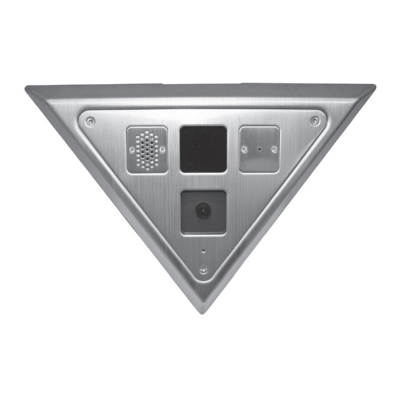
V-CELL-HD High-Security
Corner-Mount Cameras
Vicon Industries Inc.
www.vicon-security.com
XX247-10-01
Copyright © 2014 Vicon Industries Inc. All rights reserved.
User Guide
Issued: 814
Advertisement
Table of Contents

Related Manuals for Vicon XX247-10-01


Summary of Contents for Vicon XX247-10-01
- Page 1 24-Hour Technical Support: 800-34-VICON (800-348-4266) UK: 44/(0) 1489-566300 Vicon Industries Inc. does not warrant that the functions contained in this equipment will meet your requirements or that the operation will be entirely error free or perform precisely as described in the documentation. This system has not been designed to be used in life-critical situations and must not be used for this purpose.
-
Page 2: Explanation Of Graphical Symbols
WARNING TO REDUCE THE RISK OF FIRE OR ELECTRIC SHOCK, DO NOT EXPOSE THIS PRODUCT TO RAIN OR MOISTURE. DO NOT INSERT ANY METALLIC OBJECT THROUGH THE VENTILATION GRILLS OR OTHER OPENINGS ON THE EQUIPMENT. CAUTION EXPLANATION OF GRAPHICAL SYMBOLS The lightning flash with arrowhead symbol, within an equilateral triangle, is intended to alert the user to the presence of uninsulated "dangerous voltage"... -
Page 3: Fcc Compliance Statement
FCC COMPLIANCE STATEMENT INFORMATION TO THE USER : THIS EQUIPMENT HAS BEEN TESTED AND FOUND TO COMPLY WITH THE LIMITS FOR A CLASS A DIGITAL DEVICE, PURSUANT TO PART 15 OF THE FCC RULES. THESE LIMITS ARE DESIGNED TO PROVIDE REASONABLE PROTECTION AGAINST HARMFUL INTERFERENCE WHEN THE EQUIPMENT IS OPERATED IN A COMMERCIAL ENVIRONMENT. -
Page 4: Important Safety Instructions
IMPORTANT SAFETY INSTRUCTIONS 1. Read these instructions. 2. Keep these instructions. 3. Heed all warnings. 4. Follow all instructions. 5. Do not use this apparatus near water. 6. Clean only with dry cloth. 7. Do not block any ventilation openings. Install in accordance with the manufacturer’s instructions. -
Page 5: Table Of Contents
Contents 1. Description ------------------------------------------------------------------6 1.1 Components - ------------------------------------------------------------------------------------------ 6 1.2 Key Features - ------------------------------------------------------------------------------------------ 7 2. Installation ------------------------------------------------------------------- 8 2.1 Overview--------------- ------------------------------------------------------------------------------------8 2.3 Unpacking and Inspection -----------------------------------------------------------------------------11 2.4 Physical Installation -------------------------------------------------------------------------------------11 2.5 Network Connection and IP Assignment ---------------------------------------------------------- 15 3. Operation -------------------------------------------------------------------- 16 3.1 Access from a browser -------------------------------------------------------------------------------- 16 3.2 Access from the internet ------------------------------------------------------------------------------ 17 3.3 Setting the admin password over a secure connection ------------------------------------------- 17... -
Page 6: Description
Read these instructions thoroughly before beginning an installation. Refer to the complete manual for detailed information. Always refer to Vicon’s website to assure you have the most up-to-date manual, http://www.vicon- security.com. -
Page 7: Key Features
1.2 Key Features • Brilliant video quality The network camera offers the highly efficient H.264 video compression, which drastically reduces bandwidth and storage requirements without compromising image quality. Motion JPEG is also supported for increased flexibility. • Triple streams The network camera can deliver triple video streams simultaneously at full frame rate in all resolutions up to Full HD (1920x1080) using Motion JPEG and H.264 (or MPEG-4). -
Page 8: Installation
2. Installation For the network camera to operate, it is necessary to connect a network cable for data transmission and power connection from customer-supplied power supply. 2.1 Overview Parts and Description ① Main Power 24VAC/12VDC (↑(+) pole /↓(-) pole) ②... -
Page 9: Quick Installation
Quick Installation Below is an overview for installing the V-CELL-HD camera. When using 1) Installation (without Rear Cover) 1. Use camera mounting frame as template to mark mounting holes on mounting surface. (Fig.1) 2. Drill holes for mounting base and a minimum 3/4 in. hole for routing wines. (Fig.1) 3. - Page 10 2) Installation (using Rear Cover) 1. Use rear cover as template to mark mounting and cable access holes. 2. Drill mounting and cable access holes in mounting surface. 3. Insert cable clamp into access hole, route cables through clamp and mount cover using appropriate hardware.
-
Page 11: Unpacking And Inspection
2.2 Unpacking and Inspection All Vicon equipment is inspected and tested before leaving the factory. It is the carrier’s responsibility to deliver the equipment in the same condition in which it left the factory. Inspection for Visible Damage Immediately inspect the cartons upon delivery. On all copies of the carrier’s freight bill, make a note of any visible damage. -
Page 12: Mounting The Housing
5. When the camera mounting frame is secured to the surface, apply an epoxy security sealant around the perimeter of the base plate where it meets the ceiling/wall. [Vicon recommends DynaPoxy™ EP1200 (US) or Arbokol 1025 (UK) or equivalent for this purpose.] 2) Installation with the rear cover: Note: The installation corner must be sharp and clean;... -
Page 13: Cable Connections
7. When the camera mounting frame assembly is secured to the surface, apply an epoxy security sealant around the perimeter of the base plate assembly where it meets the ceiling/wall. [Vicon recommends DynaPoxy™ EP1200 (US) or Arbokol 1025 (UK) or equivalent for this purpose.] Cable Connections ... -
Page 14: Final Installation
6) Connecting Service Monitor Port The Service Monitor output port (J1) is located on the front board of the camera and is used for easy OSD setup. ▶ ID & IP assignment To make changes in the OSD menu, the optional OSD controller can be used to set the camera title and IP address. -
Page 15: Network Connection And Ip Assignment
When all connections are made, secure the front plate to the base plate using the security screws previously removed using no. 20 Torx bit. 2.4 Network Connection and IP assignment The network camera is designed for use on an Ethernet network and requires an IP address for access. Most networks today have a DHCP server that automatically assigns IP addresses to connected devices. -
Page 16: Operation
Note: For more information, refer to the Smart Manger User’s Manual. 3. Operation The network camera can be used with Windows® operating system and browsers. The recommended browsers are Internet Explorer®, Safari®, Firefox®, Opera® and Google® Chrome® with Windows. Note: To view streaming video in Microsoft® Internet Explorer, set your browser to allow ActiveX controls. -
Page 17: Access From The Internet
3.2. Access from the internet Once connected, the network camera is accessible on your local network (LAN). To access the network camera from the Internet you must configure your broadband router to allow incoming data traffic to the network camera. To do this, enable the NAT-traversal feature, which will attempt to automatically configure the router to allow access to the network camera. -
Page 18: Live View Page
3.4 Live View Page The Live View page provides several screen modes: 1920x1080, 1280x1024, 1280x720, 704x480 (576), 640x480, 352x240 (288) and 320x240. Select the most suitable in accordance with your PC specifications and monitoring purposes. 1) General controls Live View Page Search &... - Page 19 3) Video Streams The network camera provides several images and video stream formats. Your requirements and the properties of your network will determine the type you use. The Live View page in network camera provides access to H.264, MPEG-4 and Motion JPEG video streams and to the list of available video streams.
-
Page 20: Network Camera Setup
3.5 Network Camera Setup This section describes how to configure the network camera, and is intended for product Administrators, who have unrestricted access to all the Setup tools, and Operators, who have access to the settings for Basic, Live View, Video & Image, Audio, Event, and System Configuration. The network camera is configured by clicking Setup in the top right-hand corner of the Live View page. -
Page 21: Users
Enable WS-Security: Do not check this box to connect and monitor the network camera through Vicon’s viewing software using drivers older than 935. Note: WS-Security is an open format for signing and encryption of message parts, for supplying credentials in the form of security tokens, and for security passing those tokens in a message. -
Page 22: Network
2) Network The network camera supports both IP version 4 and IP version 6. Both versions may be enabled simultaneously, and at least one version must always be enabled. When using IPv4, the IP address for the network camera can be set automatically via DHCP, or a static IP address can be set manually. If IPv6 is enabled, the network camera receives an IP address according to the configuration in the network router. -
Page 23: Video & Image
3) Video & Image • Stream1 Setting Codec: The codec settings are separated into MPEG-4 and H.264. H.264 is also known as MPEG-4 Part 10. This is the new generation compression standard for digital video. This function offers higher video resolution than Motion JPEG or MPEG-4 at the same bit rate and bandwidth or the same quality video at a lower bit rate. - Page 24 Select the GOP (Group of Picture) size. If users want to have a high quality of fast image one by one, please decrease the value. For t general monitoring, do not change a basic value; such act may cause a problem to the system performance. Vicon recommends that GOP be the same as the fps.
-
Page 25: Audio
• Stream2 Setting Sometimes the image size is large due to low light or complex scenery. Adjusting the frame rate and quality helps to control the bandwidth and storage used by the Motion JPEG video stream in these situations. Limiting the frame rate and quality optimizes bandwidth and storage usage, but may give poor image quality. - Page 26 Compression type: Select the desired audio Compression format, G711. The "u-law is for North America and Japan; the "a-law" is for Europe and the rest of the world. Sample rate: Select the required Sample rate (number of times per second the sound is sampled). The higher the sample rate, the better the audio quality and the greater the bandwidth required.
-
Page 27: Date & Time
5) Date & Time • Current Server Time This displays the current date and time (24h clock). The time can be displayed in 12h clock format (see below). • New Server Time Select your time zone from the drop-down list. If you want the server clock to automatically adjust for daylight savings time, select the “Automatically adjust for daylight saving time changes”. -
Page 28: Live View
3.5.2 Live View, Source Use the Video Mode drop-down list to select the video input mode, NTSC or PAL. This defines the Video Output Port for the Service Monitor. When the settings are complete, click Save, or click Reset to revert to previously saved settings. -
Page 29: Video & Image
3.5.3 Video & Image Basic Refer to “3.5.1 Basic Configuration > Video & Image” for more details. - Page 30 Image • Image Appearance This page provides access to the advanced image settings for the network camera. Brightness: The image brightness can be adjusted in the range 1-10, where a higher value produces a brighter image. Contrast: Adjust the image's contrast by raising or lowering the value, 1-10, in this field. Saturation: Select an appropriate level by entering a value in the range 1-10.
- Page 31 AE & AWB • Exposure Control This page provides access to set the exposure and white balance of the network camera. Configure the exposure settings to suit the image quality requirements in relation to lighting consideration. Mode: Supports exposure modes to control the amount of light detected by the camera sensor based on settings for light conditions.
- Page 32 • White Balance Control This adjusts the relative amount of red, green and blue primary colors in the image so that the neutral colors are reproduced correctly. The camera can be set to automatically adjust for the type of light and compensate for its color. Alternatively, the type of light source can be set manually.
- Page 33 place. Day: Always works in day mode. Night: Always works in night mode. Threshold: Controls the how fast the change is from day to night or night to day. Select High or Low. High: Quickly changes to day mode, but slowly changes to night mode. Low: Quickly changes to night mode, but slowly changes to day mode.
- Page 34 The privacy masks are configured by Mask windows. Each window can be selected by clicking with the mouse. It is also possible to resize, delete, or move the window by selecting the appropriate window from the mouse menu on the video screen. To create a mask window, follow steps: Click the right button of mouse to see the mouse menu.
-
Page 35: Audio
3.5.4 Audio Refer to “3.5.1 Basic Configuration > Audio” for more details. -
Page 36: Event
3.5.5 Event 1) Event-In On Boot This is used to trigger the event every time the network camera is started. Select “Enable on boot” to activate the motion event. Enter the Dwell time the event lasts from the point of detection, 1-180 seconds. When the settings are complete, click Save, or click Reset to revert to previously saved settings. - Page 37 Alarm In This page allows you to configure the input supported by the camera. The Port can be defined as Normally Open or Normally Close state, and their Normal state can be configured. An input will be inactive as long as its Normal state equals its Current state. The options for Normal state are NO (Normally Open) and NC (Normally Close).
-
Page 38: Manual Trigger
Manual Trigger This option makes use of the manual trigger button provided on the Live View page, which is used to start or stop the event type manually. Alternatively the event can be triggered via the product's API (Application Programming Interface). Select “Enable manual trigger”... - Page 39 Motion Motion detection is used to generate an alarm whenever movement occurs (or stops) in the video image. A total of 8 Motion and/or Mask windows can be created and configured. Motion is detected in defined Motion windows, which are placed in the video image to target specific areas.
-
Page 40: Motion Detection Setting
To create a motion or mask window, follow steps: Click the right button of mouse to see the mouse menu. Select New Motion (or Mask) Window in the mouse menu. Click and drag mouse to designate a motion area. • Motion Detection Setting The behavior for each window is defined by adjusting the Threshold and Sensitivity, as described below. - Page 41 Network Loss This is used to trigger the event every time the network connection is failed. Select “Enable network loss” to activate the Network Loss event. Select a dwell time for how long the event will last from the point of detection. When the settings are complete, click Save, or click Reset to revert to previously saved settings.
-
Page 42: Event-Out
2) Event-Out SMTP (E-Mail) The network camera can be configured to send event and error email messages via SMTP (Simple Mail Transfer Protocol). • SMTP (E-Mail) Setting Select “Enable SMTP” to activate the SMTP operation. Sender: Enter the email address to be used as the sender for all messages sent by the network camera. - Page 43 SMTP authentication, you must define the weakest authentication method allowed. Login Method: Set the weakest method allowed to the highest/safest method supported by the mail server. The most secure method is listed in the drop-down list: Auth Login/Auth Plain • SMTP (E-Mail) Receiver Receiver: Enter an email address for a receiver.
- Page 44 actively initiates both the FTP control and data connections to the target server. This is normally desirable if there is a firewall between the camera and the target FTP server. Remote directory: Specify the path to the directory where the uploaded images will be stored.
- Page 45 • HTTP Server Setting URL: The network address to the server and the script that will handle the request. For example: http://192.168.12.244/cgi-bin/upload.cgi Port: Enter the port number used by the HTTP server. The default is 80. User name/Password: Provide your log-in information. •...
- Page 46 Audio Alert When the network camera detects an event, it can output a predefined audio data to external speaker. Check the "Enable audio alert" box to enable the service. • Audio Alert Setting To use the audio alert with the network camera, an audio data file made by user must be uploaded from your PC.
- Page 47 ▼ Record When the network camera detects an event, it can record video stream in the Micro SD Memory (not supplied) or NAS (Network Attached Device) as a storage device. Check the "Enable Record" box to enable the service. • Record Setting Overwrite: Click checkbox to overwrite the storage device;...
- Page 48 Check Audio Record box to record audio and video together. • Record Schedule The weekly recording schedule can be set for each day. Drag or click a box area; clicking the block toggles the recording between on and off. Click the “All Select” button to set a schedule for the entire week, 24/7;...
-
Page 49: Event Map
When the settings are complete, click Save, or click Reset to revert to previously saved settings. ▼ Event Notification When the network camera detects an event, it can send a message to a designated server that this event has occurred. Check the "Enable event notification" box to enable the service. Enter the notification server URL and port. - Page 50 The event map allows you to change the settings and establish a schedule for each event trigger from the network camera; up to a max. 15 events can be registered. Click the Add button to make a new event map; a popup window displays as below. To change an existing event, select that event and click the Modify button;...
-
Page 51: Device
3.5.6 Device • Enable LED Click the Enable LED checkbox to enable the Status LED When the settings are complete, click Save, or click Reset to revert to previously saved settings. -
Page 52: System
3.5.7 System 1) Information You can enter the system information. This page is very useful when you refer device information after installation. • Device Name Configuration Enter the device name. • Location Configuration Enter the location information. You can enter up to four locations. When the settings are complete, click Save, or click Reset to revert to previously saved settings. -
Page 53: Security
2) Security Users User access control is enabled by default, when the administrator sets the root password on first access. New users are authorized with user names and passwords, or the administrator can choose to allow anonymous viewer login to the Live View page, as described below: •... - Page 54 HTTPS For greater security, the network camera can be configured to use HTTPS (Hypertext Transfer Protocol over SSL (Secure Socket Layer)), so that all communication that would otherwise go via HTTP will instead go via an encrypted HTTPS connection. •...
- Page 55 IP Filtering Checking the "Enable IP address filtering" box enables the IP address filtering function. When the IP address filter is enabled, addresses added to the list are set as allowed or denied addresses. All other IP addresses not in this list will then be allowed or denied access accordingly, that is, if the addresses in the list are allowed, then all others are denied access, and vice versa.
- Page 56 OpenVPN OpenVPN is an open source software application that implements virtual private network (VPN) techniques for creating secure point-to-point or site-to-site connections in routed or bridged configurations and remote access facilities. OpenVPN can run over User Datagram Protocol (UDP) or Transmission Control Protocol (TCP) transports, multiplexing created SSL tunnels on a single TCP/UDP port.
- Page 57 • Server Mode Configuration Protocol type: Choose Protocol type between UDP and TCP, UDP is preferred. Port: Type in Port number you want to use, default is 1194. Use LZO compression: Determines whether to use cypher compression in connection or not.
-
Page 58: Date & Time
3) Date & Time • Current Server Time This displays the current date and time (24h clock). The time can be displayed in 12h clock format (see below). • New Server Time Select your time zone from the drop-down list. If you want the server clock to automatically adjust for daylight savings time, select “Automatically adjusts for daylight saving time changes”. -
Page 59: Network
4) Network Settings regarding the network can be executed. Settings for IP, DNS, Host Name, Port, and ARP/Ping can be established, along with setting for DDNS, uPnP, QoS, Zeroconfig, and Bonjour. Basic • IP Address Configuration: Obtain IP address via DHCP: Dynamic Host Configuration Protocol (DHCP) is a protocol that lets network administrators centrally manage and automate the assignment of IP addresses on a network. - Page 60 Default router: Specify the IP address of the default router (gateway) used for connecting devices attached to different networks and network segments. • IPv6 Address Configuration Check this "Enable IPv6" box to enable IPv6. Other settings for IPv6 are configured in the network router.
- Page 61 DDNS • Internet DDNS (Dynamic Domain Name Service) When using the high-speed Internet with the telephone or cable network, users can operate the network camera on the floating IP environment in which IPs are changed at every access. Users should receive an account and password by visiting a DDNS service like http://www.dyndns.com/ .
- Page 62 RTP Create a setting for sending and receiving an audio or video on a real-time basis. These settings are the IP address, port number, and Time-To-Live value (TTL) to use for the media stream(s) in multicast H.264 format. Only certain IP addresses and port numbers should be used for multicast streams.
- Page 63 RTP TTL: Enter a value between 1 and 255. If a network status is smooth, enter a lower value. However, if a network status is poor, enter a higher value. When there are many network cameras or users, a higher value may cause a heavy load to the network. Consult with a network manager for detailed information.
- Page 64 QoS Quality of Service (QoS) provides the means to guarantee a certain level of a specified resource to selected traffic on a network. Quality can be defined as a maintained level of bandwidth, low latency, and no packet losses. The main benefits of a QoS-aware network are: The ability to prioritize traffic and thus allow critical flows to be served before flows with lesser priority.
- Page 65 • Automatic Traffic Control Check the box to enable automatic traffic control. Set a limitation on user network resources by designating the maximum bandwidth. Select either the Maximum bandwidth or Automatic frame rate radio button. Maximum bandwidth: In case of sharing other network programs or equipment, it is possible to set a limitation on the maximum bandwidth in the unit of Mbit/s or kbit/s.
- Page 66 • NAT traversal Settings Enable: Click this button to enable NAT traversal. When enabled, the network camera attempts to configure port mapping in a NAT router on your network, using UPnP. Note that UPnP must be enabled in the network camera (see System>Network>UPnP). Enter a NAT router and enter the external port number for the router in the field provided.
- Page 67 Zeroconfig Zeroconfig allows the network camera to create and assign IP address for network cameras and connect to a network automatically. Zero configuration networking (zeroconf), is a set of techniques that automatically creates a usable Internet Protocol (IP) network without manual operator intervention or special configuration servers. Zero configuration networking allows devices such as computers and printers to connect to a network automatically.
- Page 68 Bonjour The network camera includes support for Bonjour. When enabled, the network camera is automatically detected by operating systems and clients that support this protocol. Click the check box to enable Bonjour. Enter a name in the Friendly name field. When the settings are complete, click Save, or click Reset to revert to previously saved settings.
-
Page 69: Language
5) Language Select a user language. The language choices are English, Korean and Russian. When the settings are complete, click Save, or click Reset to revert to previously saved settings. -
Page 70: Maintenance
6) Maintenance • Maintenance Restart: The unit is restarted without changing any of the settings. Use this method if the unit is not behaving as expected. Reset: The unit is restarted and most current settings are reset to factory default values. The settings that are not affected are: * the boot protocol (DHCP or static) * the static IP address... -
Page 71: Support
• Restore Click the Restore button to import and apply setting values saved to a user PC. Note: Backup and Restore can only be used on the same unit running the same firmware. This feature is not intended for multi-configurations or for firmware upgrades. 7) Support The support page provides valuable information when troubleshooting a problem or when contacting... - Page 72 • Health Check - System Check: Click the System Check button to get important information about the camera’s system resources. The pop-up window displays as below. - Media Check: Click the Media Check button to get information about the camera’s video and audio stream.
- Page 73 - Network Check: Click the Network Check button to get information about the camera’s network setting and traffic. The pop-up window displays as below. - Hardware Check: Click the Hardware Check button to diagnose the camera’s hardware, such as video and speaker. The pop-up window displays as below.
-
Page 74: About
3.5.8 About The following website will provide the support information for the network camera. -
Page 75: Playback
3.6 Playback The Playback window contains a list of recordings made to the memory card. It shows each recording's start time, length, the event type used to start the recording; the calendar and time slice bar indicate if the recording is exists or not. The description of playback window follows. - Page 76 Zoom In: zoom in the video clip. Full Screen: display the video full screen. (3) Time Chart Display an hour-based search screen for the chosen date. If there is recording data, a blue section will be displayed on a 24-hour basis. If you select a particular hour in the chart, a yellow square on the hour will be displayed.
-
Page 77: Help
3.7 Help The Help information window is provided as a popup window so that users can open and read it without a need for log-in. It offers descriptions of settings and a Help page, so users can manipulate the network camera without having to reference the manual. -
Page 78: Resetting To The Factory Default Settings
3.8 Resetting to the factory default settings To reset the network camera to the original factory settings, go to the Setup>System> Maintenance web page (described in “3.5.7 System > Maintenance”) or use the control button on the network camera, as described below: •... -
Page 79: Appendix
4. Appendix 4.1 Troubleshooting When troubleshooting if problems occur, verify the installation of the Network camera with the instructions in this manual and with other operating equipment. Isolate the problem to the specific piece of equipment in the system and refer to the equipment manual for further information. Problems/Symptoms Possible Causes or Corrective Actions The camera cannot be accessed... -
Page 80: Alarm Connection
4.2 Alarm Connection The following connection diagram gives an example of how to connect a network camera. 4.3 Preventive Maintenance Preventive maintenance allows detection and correction of minor faults before they become serious and cause equipment failure. Every three-month, perform the following maintenance. Inspect all connection cables for deterioration or other damage. -
Page 81: Product Specification
4.4 Product Specification Main Item Specification Image sensor 1/2.8” Exmor CMOS Active Array 1920 (H) x 1080(V) Lens Fixed 2.6mm Lens, F2.0 Angle of View 120˚(H) ~ 70˚(V) Min. illumination Color: 0.2Lux (F2.0, 50IRE) B/W: 0.0Lux (with IR LED) Shutter Speed 1/10,000 ~ 1/60 (slow shutter 1/15, 1/8 and 1/4) -. -
Page 82: System Requirement For Web Browser
System Requirement for Web Browser Operating System: Microsoft® Windows® 98, Microsoft Windows ME, Microsoft Windows 2000, Microsoft Windows XP, Microsoft Windows Vista, Microsoft Windows 7 or Microsoft Windows 8 CPU: Minimum Intel® Pentium® IV 2.4Ghz, 512MB RAM, 10GB free disk or higher. VGA: AGP, Video RAM 32MB or higher (1024x768, 24bpp or higher). -
Page 83: Shipping Instructions
Use the following procedure when returning a unit to the factory: 1. Call or write Vicon f or a Return A uthorization ( R.A.) at one of t he locations listed be low. Record the name of the Vicon employee who issued the R.A. -
Page 84: Vicon Standard Equipment Warranty
“autopan” or “tour” modes of operation. Such continuous operation is outside the scope of this warranty. Any product sold as “special” or not listed in Vicon’s commercial price list: One year from date of original retail purchase. - Page 85 Vicon Industries Inc. Internet Address: www.vicon-security.com HD V-CELL Network Camera...
Need help?
Do you have a question about the XX247-10-01 and is the answer not in the manual?
Questions and answers