
Related Manuals for OLIMEX PIC-P40-USB


Summary of Contents for OLIMEX PIC-P40-USB
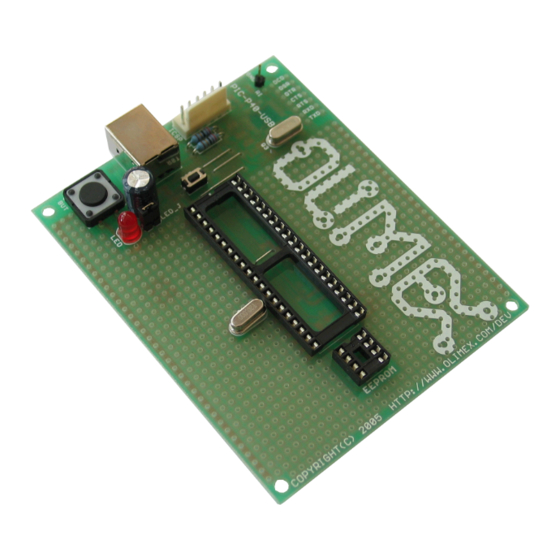
- Page 1 PIC-P40-USB development boar d User's Manual Rev.B, July 2013 Copyright(c) 2007, OLIMEX Ltd, All rights reserved...
- Page 2 INTRODUCTION: PIC-P40-USB board was designed in mind to create board which to allow easy interface for your embedded projects to computers with USB. It’s based around the popular FTDI chips FT232. Some of you will say: wait a minute why to use additional expensive chip to interface my PIC to USB when I have seen on Microchip’s web site that there are PICs with buid-in USB...
- Page 3 The RESET circuit is made with simple RC circuit. Note that RESET button should not be pressed while you program or debug the PIC! PIC-P40-USB have user button for user input connected to PIC microcontroller’s RE2 port. When RE2 port is initialized as INPUT you will read “0” when the button is pressed and “1”...
- Page 4 FEATURES: Note that: 1) There is a GND line at the bottom row of pins of the board (under button BUT). 2) There is a +5V line at the bottom row of pins of the board (above the quartz crystal) ...
- Page 5 HARDWARE:...
- Page 6 “virtual” COM port. When you open Hyperterminal on your host PC computer with 9600 bps, 8 data bit, 1 stop bit, No flow control the PIC-P40-USB every character you type on the hyperterminal will be printed back with “*” i.e. if you type “abc” you will receive “a*b*c*”.
-
Page 7: Order Code
ORDER CODE: PIC-P40-USB – assembled and tested (no kit, no soldering required) PIC-P40-USB/PCB – blank PCBs only How to order? You can order to us directly or by any of our distributors. Check our web https://www.olimex.com for more info. Revision history: REV.A... - Page 8 This document is intended only to assist the reader in the use of the product. OLIMEX Ltd. shall not be liable for any loss or damage arising from the use of any information in this document or any error or omission in such...
- Page 9 Mouser Electronics Authorized Distributor Click to View Pricing, Inventory, Delivery & Lifecycle Information: Olimex Ltd. PIC-P40-USB...
Need help?
Do you have a question about the PIC-P40-USB and is the answer not in the manual?
Questions and answers