
Related Manuals for OLIMEX PIC-MICRO-WEB


Summary of Contents for OLIMEX PIC-MICRO-WEB
- Page 1 PIC-MICRO-WEB development board User's manual Rev. E, January 2014 Copyright(c) 2011, OLIMEX Ltd, All rights reserved Page 1...
-
Page 2: Board Features
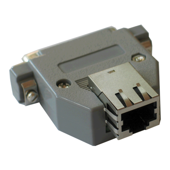
Packed in compact plastic enclosure with DB25 male connector for the microcontroller ports and with the unique PoE (Power over Ethernet) feature which allows PIC-MICRO-WEB to take power by the Ethernet cable and with no need for external power supply adapter. -
Page 3: Processor Features
(24-50VDC) directly to DB25.pin8. Software: PIC-MICRO-WEB is tested with MPLAB IDE v.7.62 + MPLAB C18 C compiler. It is possible that the stack might not function properly if used with later versions of MPLAB IDE. - Page 4 Selectable polarity Programmable dead time Auto-shutdown and auto-restart Up to Two Master Synchronous Serial Port (MSSP) modules supporting SPI (all 4 modes) and I2C™ Master and Slave modes Up to Two Enhanced USART modules: Supports RS-485, RS-232 and LIN 1.2 Auto-wake-up on Start bit Auto-Baud Detect (ABD) 10-Bit, Up to 16-Channel Analog-to-Digital Converter module (A/D):...
-
Page 5: Block Diagram
BLOCK DIAGRAM: Page 5... -
Page 6: Memory Map
MEMORY MAP: Page 6... - Page 7 Page 7...
- Page 8 SCHEMATIC: CE220uF/10V CE220uF/10V Page 8...
-
Page 9: Reset Circuit
The board power consumption depends on the applied power supply and may vary. At 24VDC the consumption is about 40 mA. RESET CIRCUIT: PIC-MICRO-WEB reset circuit is made with R20 (10k) pull-up, R13 (330Ω) and capacitor C31 (100nF). CLOCK CIRCUIT: Quartz crystal 25 MHz is connected to PIC18F67J60 pin 39 clock in (OSC1/CLKI) and pin 40 clock out (OSC2/CLKO). - Page 10 Input Program Clock. Clock used for transferring the serial data (output from ICSP, input for the MCU). DB25: Pin # Signal Name Pin # Signal Name RA4/T0CKI RA0/LEDA/AN0 RC2/ECCP1/P1A RA2/AN2/VREF- RC7/RX1/DT1 VCC +3.3V RE1/P2C RD2/CCP4/P3D RE3/P3C RE4/P3B RD0/P1B RA5/AN4 RA1/LEDB/AIN1 RA3/AN3/VREF+ RC6/TX1/CK1 RF2/AN7/C1OUT...
- Page 11 LAN: Pin # Signal Name Chip Side Pin # Signal Name Chip Side TPOUT+ TPIN- TPOUT- TPIN+ Not Connected (NC) 3.3V Not Connected (NC) TPOUT- Output Differential signal output. TPOUT+ Output Differential signal output. TPIN- Input Differential signal input. TPIN+ Input Differential signal input.
-
Page 12: Available Demo Software
AVAILABLE DEMO SOFTWARE : You could find information about PIC-MICRO-WEB board, Microchip TCP/IP stack and how to change and configure the software on Understanding PIC WEB boards here: https://www.olimex.com/Products/PIC/_resources/Understanding-PIC-WEB- boards.pdf Page 12... -
Page 13: Order Code
ORDER CODE: PIC-MICRO-WEB – assembled and tested (no kit, no soldering required) How to order? You can order to us directly or by any of our distributors. Check our web page https://www.olimex.com/ for more info. All boards produced by Olimex are RoHS compliant... - Page 14 This document is intended only to assist the reader in the use of the product. OLIMEX Ltd. shall not be liable for any loss or damage arising from the use of any information in this document or any error or omission in such information or any incorrect use of the product.
- Page 15 Mouser Electronics Authorized Distributor Click to View Pricing, Inventory, Delivery & Lifecycle Information: Olimex Ltd. PIC-MICRO-WEB...
Need help?
Do you have a question about the PIC-MICRO-WEB and is the answer not in the manual?
Questions and answers