Table of Contents
Advertisement
Quick Links
The Challenge Machinery Company provides owner's manuals on its
products solely as a courtesy to its customers. See the information below
before using this manual.
These manuals are for reference only. These manuals include products which are noncurrent,
unsupported or no longer produced by The Challenge Machinery Company, and are provided solely as
an accommodation to our customers. By providing these manuals, The Challenge Machinery Company
makes no representation or warranty as to the products, their current condition, or their suitability or fitness
for use in any particular application, which are the sole and independent responsibility of the product
owner and user.
Older products may not comply with current safety procedures, guidelines or regulations, and it
is the product owner's and user's responsibility to evaluate the suitability and fitness of the
products in their current use and application. The Challenge Machinery Company makes no
representation, warranty or recommendation regarding any modifications which may be required
on non-current or unsupported products. The Challenge Machinery Company assumes no liability
for any modification or alteration to any Challenge product, and any such modification or
alteration to any Challenge product is not authorized by The Challenge Machinery Company. The
availability of these manuals is solely for the purpose of providing reference information for the products.
This manual may not be complete in all aspects of product maintenance and repair. All products should
be used only by qualified and properly trained personnel, following proper safety procedures. All
products should be regularly inspected and maintained, and their condition, application and use should
be periodically evaluated by qualified personnel. Only qualified and properly trained technicians should
perform maintenance, repair and replacement procedures. Attempting these procedures without proper
training may cause machine damage or operator injury!
Products may be unsupported by The Challenge Machinery Company due to age or the unavailability of
parts from their original manufacturer. No parts or product support will be available to repair or maintain
unsupported products. Older products may not be UL listed (if the product does not have a UL label it is
not a listed product), and may not comply with applicable installation or other regulations or requirements
if relocated to a new facility. Many municipalities require a product to be UL listed before an electrician
will connect power to them. Often the cost of updating an older product to comply with current safety
regulations is greater than the value of the product.
SPARTAN 150 SA
Technical Service and Parts Manual
Serial Numbers:
041001 through 159999,
150-A-150000 and up
Sold and Serviced by
The Challenge Machinery Company
6125 Norton Center Drive
Norton Shores, MI 49441-6081 USA
F.150-T
ChallengeMachinery.com
November 2016
Advertisement
Table of Contents

Related Manuals for Challenge SPARTAN 150 SA


Summary of Contents for Challenge SPARTAN 150 SA
- Page 1 Products may be unsupported by The Challenge Machinery Company due to age or the unavailability of parts from their original manufacturer. No parts or product support will be available to repair or maintain unsupported products.
-
Page 2: Introduction
Always give the SERIAL NUMBER and MODEL of your machine to insure the correct parts are sent as soon as possible. Challenge® is a registered trademark of The Challenge Machinery Company 6125 Norton Center Drive Norton Shores, MI 49441-6081... - Page 3 1.0 Introduction TABLE OF CONTENTS 1.0 Introduction ............................2 2.0 Safety ..............................4 2.1 Precautions ...........................4 2.2 Power Lockout Procedure ......................4 2.3 Warning Label Definitions ......................5 3.0 Maintenance Guide ...........................7 3.1 Routine Maintenance ........................8 3.1.1 Weekly ...........................8 3.1.2 Monthly ..........................8 3.1.3 Yearly ............................8 3.2 Cleaning ............................8 3.2.1 Table ............................8 3.2.2 Display Panel ........................8...
-
Page 4: Power Lockout Procedure
2.0 Safety 2.0 Safety 2.1 Precautions This machine is designed for one-person operation. Never operate the machine with more than one person. Safe use of this machine is the responsibility of the operator. Use good judgment and common sense when working with and around this machine. -
Page 5: Warning Label Definitions
2.0 Safety 2.3 Warning Label Definitions The following warning labels are found at various locations on your machine. Read and understand the meaning of each symbol. If a label is lost from the machine, it should be replaced. HAZARDOUS AREA Disconnect power before cleaning, servicing, or making adjustments not requiring power. - Page 6 2.0 Safety !OJO! This Este simbolo de alerta de seguridad significa ¡ OJO ! - INSTRUCCIONES DE SEGURIDADPERSONAL. Lea las instrucciones porque se refieren a su seguridad personal. Fall de obedecer las instrucciones que siguen podria resultar en lesiones corporales. ...
-
Page 7: Maintenance Guide
Challenge. The Challenge Machinery Company assumes no liability for any modification or alteration to any Challenge products, and any such modification or alteration to any Challenge product is not authorized by The Challenge Machinery Company. Any modification or alteration of any Challenge product... -
Page 8: Display Panel
3.0 Maintenance Guide 3.1 Routine Maintenance DISCONNECT POWER before making any adjustments or lubricating. See page 4, SAFETY PRECAUTIONS, for Power Lockout Procedure. A clean, lubricated machine will run longer, smoother, cut more accurately, with less downtime and fewer costly repairs. Schedule lubrication both early in the day and early in the week. This allows the lubricants to work into the machine. -
Page 9: Machine Exterior
3.0 Maintenance Guide 3.2.3 Machine Exterior The machine’s exterior should be cleaned with a non-abrasive water based detergent applied to a damp cloth. Always be careful when cleaning around safety warning labels. Use limited amounts of cleaners in those areas. 3.3 Lubrication 3.3.1 Clamp Send the knife down by activating a cut cycle and when the knife reaches the bottom, release only... -
Page 10: Backgauge Leadscrew
3.0 Maintenance Guide 3.3.2 Backgauge Leadscrew With the top cover ON, place machine on a flat level surface on it’s left side and remove bottom cover. Use any brand-name type of grease or light oil to lubricate backgauge leadscrew (Figure 4). It may be helpful to use a small brush to apply grease. - Page 11 3.0 Maintenance Guide Figure 5 Figure 6Figure 7 To square the backgauge: 1. Make sure the backgauge gibs are set properly (see section 3.4.5 ). 2. Remove the rear Plexiglas table cover. 3. Loosen the jam nuts on the backgauge adjusting screws. (Figure 8). Backgauge Backgauge Adjusting...
-
Page 12: Backgauge Accuracy Adjustment
3.0 Maintenance Guide Note: Once the backgauge is square, check the backgauge accuracy (see section 3.4.2 ) to make sure it is accurate. 3.4.2 Backgauge Accuracy Adjustment If the backgauge position readout does not match the actual measurement between the knife and the backgauge, the accuracy can be adjusted. -
Page 13: Knife Bar Gib Adjustments
3.0 Maintenance Guide Preset Screw Figure 10 5. Replace bottom cover, lay machine flat, and turn on power. Note: If power was not off, reset power now or else reading will be false. Bring the backgauge to the front to reset the display and make another test. -
Page 14: Knife Leveling Adjustment
3.0 Maintenance Guide 5. Replace top cover, plug in power cord, turn power on, and start a cut cycle. 6. When knife is all the way down, release right cut button only and switch off power. 7. Now with the knife in the down position, disconnect power cord, remove top cover, and repeat gib screw adjustment for the BOTTOM GIB SCREW on each side. -
Page 15: Backgauge Gib Adjustments
3.0 Maintenance Guide 6. Slightly loosen the remaining (5) knife screws, keeping them somewhat snug. 7. Adjust the knife leveling screw (Figure 13) that corresponds with the side of the knife which does not cut all the way through. Tug on the paper while adjusting and stop when the bottom sheet is cut all the way through. -
Page 16: Leadscrew Collars
3.0 Maintenance Guide Backgauge Backgauge Gib Screw Gib Screw Figure 14 4. Tighten the two nylon set screws until they just touch the guide. Do not over-tighten or they could cause the backgauge to bind. Lock in position with jam nuts. The center screw is a spring loaded plunger and should not need adjustment. -
Page 17: Line Light Adjustment
3.0 Maintenance Guide Leadscrew Collars Figure 15 4. Make sure there is a slight gap between the front hand crank and the machine, slide collars up tight against the nylon washers and tighten the collar screws. 5. Check to make sure the hand crank turns freely with no play. 6. -
Page 18: Front Guard Switch Adjustment
3.0 Maintenance Guide Line Light Mounting Screws Figure 16 3. Place a white sheet of paper over the cut stick and turn the power on to activate the line light. Note: 24V is being supplied to line light board while power is on. 4. -
Page 19: Knife Up Limit Switch Adjustment
3.0 Maintenance Guide Hinge Rod Mounting Screws Figure 17 4. Tighten screws, replace cover and clamp handle. 5. Test to make sure machine works properly, using the test found at the end of this manual. 3.4.9 Knife Up Limit Switch Adjustment If the knife up limit switch becomes loose or needs adjustment, adjust as follows: 1. -
Page 20: Knife Down Limit Switch Adjustment
3.0 Maintenance Guide Mounting Screws Figure 18 5. Replace bottom cover, lay machine flat, and turn on power. Make a cut. Check position of knife – USE CAUTION, THE KNIFE EDGE IS VERY SHARP. The edge of a new knife should be above the bottom of the clamp when the knife and clamp are in the “up”... -
Page 21: Backgauge Encoder/Belt Adjustment
3.0 Maintenance Guide Bracket Mounting Screws Limit Switch Switch Bracket Figure 19 4. Check to make sure the switch bracket slides freely on the mounting bracket. 5. Check condition of spring. 6. Replace bottom cover and lay machine flat. 3.4.11 Backgauge Encoder/Belt Adjustment The backgauge encoder system reads the position of the backgauge, and sends the information to the display. -
Page 22: Re-Engaging The Knife Pull-Down Gear
3.0 Maintenance Guide Belt Encoder Pulley Bracket Mounting Screws Figure 20 4. Inspect the belt and make sure it is tight. If it is not, loosen the (2) screws at the rear of the machine, pull belt tight, then tighten the screws. 5. - Page 23 3.0 Maintenance Guide Disengage Brake Figure 21 4. Now move the gears in the directions shown in Figure 21. Some machines are equipped with gears that have a small stub on them which can be used to turn the gear using a pliers or wrench if necessary.
-
Page 24: Troubleshooting
3.0 Maintenance Guide 6. Check to make sure the up and down limit switches are positioned properly to prevent gears from becoming disengaged again (See Section 3.4.9 page 19 and Section 3.4.10 page 20). 7. Replace bottom cover and lay machine flat. 3.5 Troubleshooting Problem Possible Cause... - Page 25 3.0 Maintenance Guide Problem Possible Cause Solution 6. Backgauge display is a) Backgauge accuracy needs a) See Section 3.4.2 Backgauge inaccurate. adjustment. Accuracy Adjustment, page 12. b) Encoder malfunction. b) Check encoder system (see Section 3.4.11 Backgauge Encoder/Belt Adjustment, page 21) or replace encoder.
-
Page 26: Parts Lists
4.0 Parts Lists 4.0 Parts Lists 4.1 Main Assembly – Backgauge Bracket 60000-SA Sheet 1, Rev. G... - Page 27 4.0 Parts Lists PART NO. DESCRIPTION 60042 DOUBLE NUT- #6-32 60075 KNOB - 5 LOBE, SOFT TOUCH 60096 HANDWHEEL LOCK BLOCK 60098 HANDWHEEL LOCK ADJ. ROD 60100 BASE WELDMENT 60206 GUIDE SHAFT BRACKET 60208 TIMING PULLEY- 25 GROOVE MXL 60209 ENCODER MOUNTING BRACKET 60211 BELT- MXL...
-
Page 28: Main Assembly – Leadscrew
4.0 Parts Lists 4.2 Main Assembly – Leadscrew 60000-SA Sheet 2, Rev. D... - Page 29 4.0 Parts Lists PART NO. DESCRIPTION 60043 HANDCRANK - BACKGAUGE 60115 ADJUSTABLE PILLOW BLOCK 60210 LEADSCREW 11288-5 NYLON WASHER A-10081-4 SPLIT COLLAR H-6918-406 SCREW - 1/4-20 X 3/4 SOCKET HEAD CAP H-7321-4 WASHER - 1/4 SAE PLAIN H-7327-8 WASHER - 1/4 MEDIUM LOCK S-1781-124 FRONT LABEL...
-
Page 30: Main Assembly – Knife Drive
4.0 Parts Lists 4.3 Main Assembly – Knife Drive 60000-SA Sheet 3, Rev. G... - Page 31 4.0 Parts Lists PART NO. DESCRIPTION 60005 MOTOR AND GEARBOX ASM - 120V, 60HZ 60010 PULL-DOWN LINK 60028 PIN - LOWER PULL DOWN 60038 LOWER LIMIT SWITCH BRACKET 60039 UPPER LIMIT SWITCH BRACKET 60111 SWITCH ADJUSTMENT BRACKET 35048-21 COMPRESSION SPRING 61034-250032 SHLD SCR LENGTHENING SHIM- 1/4 E-1152-71...
-
Page 32: Main Assembly – Bottom Side Electrical
4.0 Parts Lists 4.4 Main Assembly – Bottom Side Electrical 60000-SA Sheet 4, Rev. D... - Page 33 4.0 Parts Lists PART NO. DESCRIPTION 47214-1 SHOULDER WASHER E-3074 CIRCUIT BREAKER AND ON/OFF SWITCH - 8 AMP E-3117 BOOT - RUBBER, MOTOR CAPACITOR E-3129 PUSHBUTTON SWITCH E-1152-56 STANDOFF E-1152-71 STANDOFF E-2416-5 CAPACITOR - 80 MFD E-2626-2 TERMINAL STRIP (2P) E-2709-4 BRACKET - CAPACITOR (80 MFD) EE-3188...
-
Page 34: Main Assembly – Clamp
4.0 Parts Lists 4.5 Main Assembly – Clamp 60000-SA Sheet 5, Rev. H... - Page 35 4.0 Parts Lists PART NO. DESCRIPTION 60017 TORSION BAR 60018 TORSION LINK 60093 HANDWHEEL - CLAMP 61025 CLAMP 61026 CLAMP LEADSCREW 61027 ARCH WELDMENT - 150SA, 150M 61066 CLAMP NUT 20075-10 SHIM 61065-313032 SHLD SCR SHORTENING SHIM- 5/16 H-5246-416 DOWEL PIN - 1/4 X 2 HD GD H-5254-502 SCREW - 5/16 X 1/4 SHSS H-5254-503...
-
Page 36: Main Assembly – Knife
4.0 Parts Lists 4.6 Main Assembly – Knife 60000-SA Sheet 6, Rev. D... - Page 37 4.0 Parts Lists PART NO. DESCRIPTION 60002 KNIFE BAR 60003 ROLLER 60011 KNIFE 60014 ROLLER DISK 60030 PIN - UPPER PULL DOWN 60057 CUT STICK 60064 KNIFE BAR MOUNTED GUARD 56256 GIB INSERT (S/N 051260 AND BELOW) 60074 GIB INSERT (S/N 051261 AND ABOVE) 60089 CLAMP GUIDE BLOCK 60015...
-
Page 38: Main Assembly – Front Shield
4.0 Parts Lists 4.7 Main Assembly – Front Shield 60000-SA Sheet 7, Rev. D... - Page 39 4.0 Parts Lists PART NO. DESCRIPTION 60035 TILT SHIELD 60047 HANDLE - SHIELD 60048 SHIELD BRACKET 60049 DAMPENING TUBE 60051 TORSION SPRING 60052 MAGNET ASSEMBLY 60036-1 HINGE ROD 60037-1 SHIELD BRACKET E-866-9 POSITIVE ACTION MICROSWITCH H-5254-402 SCREW - 1/4 X 1/4 SHSS H-6423-N4 NUT - #4-40 HEX KEP H-6910-410...
-
Page 40: Main Assembly – Backgauge
4.0 Parts Lists 4.8 Main Assembly – Backgauge 60000-SA Sheet 8, Rev. G... - Page 41 4.0 Parts Lists PART NO. DESCRIPTION 60044 SIDE GUIDE 60203 BACKGAUGE ASSEMBLY H-6910-405 SCREW - 1/4-20 X 5/8 BUTTON HEAD CAP H-6918-606 SCREW - 3/8-16 X 3/4 SOCKET HEAD CAP H-6938-416 SCREW - 1/4-20 X 1 CUP SOC SET H-6947-405 SCREW - 1/4-20 X 5/8 FULL DOG POINT SOC SET H-7321-4 WASHER - 1/4 SAE PLAIN...
-
Page 42: Main Assembly – Top Side Electrical
4.0 Parts Lists 4.9 Main Assembly – Top Side Electrical 60000-SA Sheet 9, Rev. D... - Page 43 4.0 Parts Lists PART NO. DESCRIPTION 60040 LINE LIGHT BRACKET EE-3081 BOARD H-6910-102403 SCREW - #10-24 X 3/8 BUTTON HEAD CAP H-6918-83203 SCREW - #8-32 X 3/8 SOCKET HEAD CAP H-7321-N8 WASHER - #8 SAE PLAIN H-7327-N8 WASHER - #8 MEDIUM LOCK H-7327-N10 WASHER - #10 MEDIUM LOCK S-1694-1...
-
Page 44: Main Assembly – Covers And Labels
4.0 Parts Lists 4.10 Main Assembly – Covers and Labels 60000-SA Sheet 10, Rev. D... - Page 45 4.0 Parts Lists PART NO. DESCRIPTION 41130 PLATE - SERIAL NUMBER 60021 TOP COVER 60056 BOTTOM COVER 60062 REAR COVER 60073 ABSORBANT MAT 5177-3 LABEL - UL LISTING 5177-4 LABEL - UL/CSA LISTING A-11074-1 FOOT - RUBBER H-6423-N10 NUT - #10-24 HEX KEP H-6910-102404 SCREW - #10-24 X 1/2 BUTTON HEAD CAP H-6910-102408...
-
Page 46: Main Assembly – Accessories
4.0 Parts Lists 4.11 Main Assembly – Accessories 60000-SA Sheet 11, Rev. D PART NO. DESCRIPTION 5064 CUT STICK PULLER 60058 JOGGING AID 60061 KNIFE LIFTER ASM W-189 WRENCH - 5/32" T-HANDLE HEX ALLEN... -
Page 47: Motor And Gearbox Assembly
4.0 Parts Lists 4.12 Motor and Gearbox Assembly 60005 Rev. D PART NO. DESCRIPTION 60004 GEARBOX 60029 CAP - GEARBOX 60033 60034 GASKET - GEARBOX 60067 OIL SEAL E-1600-197 MOTOR W/ BRAKE - BALDOR H-6910-403 SCREW - 1/4-20 X 3/8 BUTTON HEAD CAP H-6910-102404 SCREW - #10-24 X 1/2 BUTTON HEAD CAP H-6918-410... -
Page 48: Backgauge Assembly
4.0 Parts Lists 4.13 Backgauge Assembly 60203 PART NO. DESCRIPTION 60201 BACKGUAGE- MACHINED 60204 FLOATING FINGER H-5246-406 DOWEL PIN - 1/4 X 3/4 HD GD 4.14 Magnet Assembly 60052 PART NO. DESCRIPTION 60046 BLOCK - HOOD HANDLE 60053 MAGNET - RARE EARTH H-21S-187-0500 ROLL PIN - 3/16 X 1/2... -
Page 49: Electrical Power Panel Assembly
4.0 Parts Lists 4.15 Electrical Power Panel Assembly EE-3061, Rev. B (120V Opt) and EE-3136 (220V Opt) -
Page 50: Wire Harness Assembly
4.0 Parts Lists 4.16 Wire Harness Assembly EE-3116, Rev. C... - Page 51 4.0 Parts Lists Wire Harness Assembly EE-3116, Rev. C...
-
Page 52: Electrical Schematic
4.0 Parts Lists 4.17 Electrical Schematic E-3062 rev A (120 Volt) -
Page 53: Electrical Schematic
4.0 Parts Lists 4.18 Electrical Schematic E-3135 rev. A (220 Volt Option) -
Page 54: Electrical Interconnection Diagram
4.0 Parts Lists 4.19 Electrical Interconnection Diagram E-3125 Rev. D (120 Volts) -
Page 55: Electrical Interconnection Diagram
4.0 Parts Lists 4.20 Electrical Interconnection Diagram E-3125-1 Rev. B (220 Volts Option) -
Page 56: Label – Fuse Replacement
4.0 Parts Lists 4.21 Label – Fuse Replacement S-1781-129, Rev. B... -
Page 57: Label – Fuse Replacement
4.0 Parts Lists 4.22 Label – Fuse Replacement S-1781-140, Rev. B (220 Volt Option) -
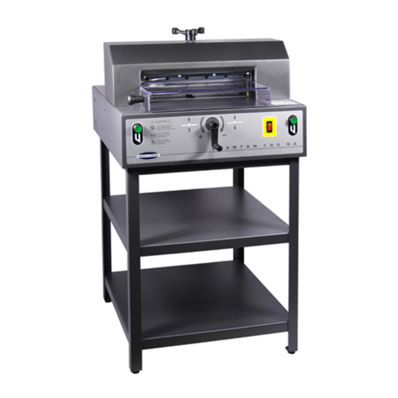
Page 58: Optional Floor Stand Assembly
4.0 Parts Lists 4.23 Optional Floor Stand Assembly 60065, Rev. B PART NO. DESCRIPTION 60069 STAND WELDMENT 40016-6 MOUNT - VIBRATION H-6925-412 SCREW - 1/4-20 X 3/4 TRUSS HD MACH... - Page 59 4.0 Parts Lists BLANK...
- Page 60 F.150-T November 2016...
Need help?
Do you have a question about the SPARTAN 150 SA and is the answer not in the manual?
Questions and answers