
Related Manuals for OpenEye CM-300H


Summary of Contents for OpenEye CM-300H
-
Page 1: User Manual
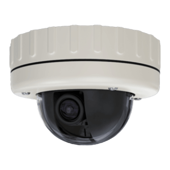
300 Series Dome Camera Vandal Proof Outdoor Dome User Manual CM-300H model no. CM-300 Please carefully read these instructions before using this product. Save this manual for future use. 27791AE... -
Page 2: Regulatory Compliance
POWER SUPPLY REQUIREMENTS: For use with listed Audio/Video Product and only connected to 15W or less power supply. ATTENTION: The information in this document is subject to change without notice. OpenEye shall not be liable for technical, editorial errors or omissions contained herein. -
Page 3: Table Of Contents
Contents Regulatory Compliance ..................Contents ........................ Mounting Guide ....................Precaution ......................Methods for Mounting the Enclosure ..............Packing List ...................... Installing the Dome Enclosure ................. Camera Adjustments ..................Camera Adjustments for the 300 Series ............Camera Specifications ..................Template ...................... -
Page 4: Mounting Guide
Mounting Guide Turn silver-colored screws clockwise to first extend the locking arms and then tighten them against the mounting surface. Tighten the screws sufficiently to compress the o-ring moisture seals located underneath the screwheads. DO NOT OVERTIGHTEN Rubber o-rings maintain the moisture seal when installing externally. -
Page 5: Precaution
Mounting Guide Precautions • Do not attempt to disassemble the camera module mounted within the dome. There are no user-serviceable parts within the camera module. Refer servicing to qualified service personnel. • Handle the camera with care. Do not abuse the camera. Avoid striking or shaking it. -
Page 6: Installing The Dome Enclosure
Mounting Guide Installing the Dome Enclosure Threaded base cable entry (¾” sealing plug (D8) supplied) Washer and screw for strain relief Threaded side entry (with ½” sealing plug (D8) fitted) Outer ring large knock-out for ½” conduit entry Outer ring small knock-out for cable-only entry Large rubber gasket Index slots for Dome Lid Conduit entry sealing plugs... -
Page 7: Adjust Camera Position
Mounting Guide Installing the Dome Enclosure Remove Bubble Liner G1: Camera Liner G2: External Positioning Ring G3: Positioning Screws G4: Internal Positioning Ring Adjust Camera Position Rotate and pan the internal positioning ring (G4) to the desired position. Slightly tighten the positioning screws (G3) on both sides. - Page 8 Installing the Dome Enclosure Remove the dome cover Use the supplied Torx driver to loosen, if required, (but not remove) the four cover screws. The screws are captive and will be retained in the lid. Use the template to mark and prepare the mounting area All mounting access positions are sealed until they are ready to be used.
- Page 9 Installing the Dome Enclosure Fit the camera assembly Connect the camera to the fly-connector (E3). This lead and the one that it connects with are multi-colored. Place the complete camera assembly (F1) onto the three mounting pillars (F3) within the enclosure. Insert and slightly tighten the three nickel-colored gimbal securing screws (F2).
-
Page 10: Camera Adjustments
Camera Adjustments H 300 Series High Resolution Color Camera H A S A L C – H1: Focus Adjust B . E H2: Field of View Adjust N . S I N T H3: DIP Switches B L C H4: ALC Adjustment A G C H5: V-PHASE Adjustment Camera Adjustments for the 300 Series High Resolution Color... -
Page 11: Camera Specifications
Camera Specification 300 Series High Resolution Camera Specification Image Picture Element 1/3” Interline CCD 768(H) x 494(V) Resolution (TV lines) 540 (normal) i n i u l l Back Light Compensation Central area for Auto Iris Line Lock (Phase Adj. Range) ~270 Line Lock (Frequency Range) 60Hz ±1Hz... -
Page 12: Template
Template Surface mount Flush mount Create four ¼” (7mm) diameter holes at template Create an aperture in the mounting surface to a diameter positions ‘T1’. Use 4 x wall plugs and 4 x (no.12 x 1½”) of 4.3” (110mm) as indicated by ‘T5’. screws.
Need help?
Do you have a question about the CM-300H and is the answer not in the manual?
Questions and answers