
Related Manuals for OpenEye XM5000


Summary of Contents for OpenEye XM5000
-
Page 1: User Manual
410-Series Camera Mini Speed Dome User Manual CM-410 XM5000 model no. model no. Please carefully read these instructions before using this product. 28561AA Save this manual for future use. - Page 2 THE INFORMATION IN THIS PUBLICATION IS PROVIDED “AS IS” WITHOUT WARRANTY OF ANY KIND. THE ENTIRE RISK ARISING OUT OF THE USE OF THIS INFORMATION REMAINS WITH RECIPIENT. IN NO EVENT SHALL OPENEYE BE LIABLE FOR ANY DIRECT, CONSEQUENTIAL, INCIDENTAL, SPECIAL, PUNITIVE, OR OTHER DAMAGES WHATSOEVER (INCLUDING WITHOUT LIMITATION,...
-
Page 3: Important Safeguards
Important Safeguards Read Instructions Read all of the safety and operating instructions before using the product. Retain Instructions Save these instructions for future reference. Attachments / Accessories Do not use attachments or accessories unless recommended by the appliance manufacturer as they may cause hazards, damage product and void warranty. -
Page 4: Explanation Of Graphical Symbols
WARNING DANGEROUS HIGH VOLTAGES ARE PRESENT INSIDE THE ENCLOSURE. DO NOT OPEN THE CABINET. REFER SERVICING TO QUALIFIED PERSONNEL ONLY. CAUTION C A U T I O N RISK OF ELECTRIC SHOCK DO NOT OPEN CAUTION: TO REDUCE THE RISK OF ELECTRIC SHOCK, DO NOT REMOVE COVER (OR BACK). -
Page 5: Standard Warranty
Standard Warranty Openeye warrants all products to be free from defects in workmanship and material under normal use for a period of one year after the date of purchase. Any defective product that falls under this warranty will, at OpenEye's discretion, be repaired or replaced at no additional charge. - Page 6 NOTES: 28561AA...
-
Page 7: Table Of Contents
Table of Contents INTRODUCTION ......................1 FEATURES .............................. 1 Camera Specifications ......................... 1 Advanced Pan/Tilt Functions ....................... 1 Preset, Pattern, Swing, Group, and Privacy Mask ................1 PTZ (Pan/Tilt/Zoom) Control ........................ 1 OSD (On-Screen Display) ........................1 Alarm I/O Functions ..........................2 Reserved Presets for Special Purpose .................... - Page 8 Privacy Zone Size Adjustment ......................23 CAMERA SETUP ............................ 24 White Balance ............................. 24 AE Setup (Auto Exposure) ........................25 MOTION SETUP ............................. 26 Parking Action Setup .......................... 26 Alarm Input Setup ..........................27 PRESET SETUP ............................. 27 Edit Preset Scene ..........................28 Edit Preset Label ..........................
- Page 9 NOTES: 28561AA...
- Page 10 NOTES: 28561AA...
-
Page 11: Introduction
INTRODUCTION FEATURES CAMERA SPECIFICATIONS • CCD Sensor : 1/4" Interline Transfer CCD • Zoom Magnification : × 10 Optical Zoom, × 10 Digital Zoom (Max × 100 Zoom) • Day & Night Function • Various Focus Mode: Auto-Focus / Manual Focus / Semi-Auto Focus. •... -
Page 12: Alarm I/O Functions
ALARM I/O FUNCTIONS • 4 alarm sensor Inputs are available. • To completely eliminate external electric noise and shock, alarm sensor Input is decoupled from photo coupler. • The signal range of sensor Input is from 5 to 12 volts DC to adapt to various applications. •... -
Page 13: Product & Accessories
PRODUCT & ACCESSORIES Main Body Surface Mount Bracket Screws and Terminal Block OPTIONAL ACCESSORIES Flush Mount Kit Ceiling Mount Bracket Wall Mount Bracket 28561AA... -
Page 14: Part Names And Functions
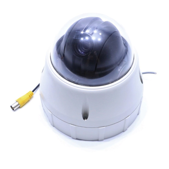
PART NAMES AND FUNCTIONS Surface Mount Bracket Mounting Hole Safety Retention Spring Main Body Lock-up Screw Cabling Terminal Block DIP Switch Dome Cover Main Unit / Surface Mount Bracket Back of Main Unit Do not remove protective vinyl from dome cover before finishing all installation processes to protect Dome Cover dome cover from scratches or dust. -
Page 15: Dip Switch Setup
DIP SWITCH SETUP Before you install the camera, you should set the DIP switches to configure the camera ID and communication protocol. Communication Camera ID Protocol CAMERA ID SETUP • ID number of camera is set using a binary number. Example is shown below. ID Value ex) ID=5 ex) ID=10... -
Page 16: Reserved For Supplier
RESERVED FOR SUPPLIER • Since Pin 3 ~ Pin 4 are only for supplier, DO NOT CHANGE THEIR ORIGINAL SETTINGS. If settings are changed, camera will not operate properly. PAL / NTSC system selection of Camera. DO NOT CHANGE Pin 3 THIS PIN. -
Page 17: Installation
INSTALLATION DIRECT INSTALLATION ON THE CEILING To pass cables to upside of ceiling, cut a 2~2.5 inch Fasten surface mount bracket to ceiling with 4 screws. (50~60mm) hole in the ceiling panel. Wire cables to terminal block and connect the terminal Fasten main unit to surface mount bracket with 4 lock-up blocks to main unit. -
Page 18: Installation Using The Ceiling Mount Bracket
INSTALLATION USING THE CEILING MOUNT BRACKET Fasten ceiling mount bracket to the ceiling with 3 screws. Wire cables to terminals and connect the terminals to main unit. Do not use surface mount bracket! Fasten main unit to ceiling mount bracket with 4 screws. Remove protective vinyl from dome cover. -
Page 19: Installation Using The Wall Bracket
INSTALLATION USING THE WALL BRACKET Fasten the wall bracket to the ceiling with 3 screws. Wire cables to terminals and connect the terminals to main unit. Do not use surface mount bracket! Fasten main unit to wall mount bracket with 4 screws. Remove protective vinyl from dome cover. -
Page 20: Installation With Flush Mount Kit
INSTALLATION WITH FLUSH MOUNT KIT Cut holes in the ceiling. (Image not to scale) Align main body bracket with Flush Mount Kit. Fasten with screws. 65mm (2.56”) Connect fall-proof spring to main body hook. Assemble and Put main body and bracket assembly into main hole. fasten with screws. -
Page 21: Cabling
CABLING Power IrDA Sensor Door Controller/ DVR S witch Sensor Monitor Cabling Terminal Block POWER CONNECTION • Check the voltage and current capacity of rated power carefully. Rated power is indicated on the back of the main unit. Rated Power Input Voltage Range Current Consumption AC 24V... -
Page 22: Rs-485 Communication
For PTZ control, connect this line to the keyboard and DVR. To control multiple cameras at the same time, RS-485 communication lines to cameras are connected in parallel as shown below. • OpenEye recommends Category 5 or 6 Twisted Pair Cable for the RS-485 wire Keyboard Controller/ DVR RS-485 VIDEO CONNECTION •... - Page 23 NOTES: 28561AA...
- Page 24 NOTES: 28561AA...
-
Page 25: Operation
OPERATION CHECK POINTS BEFORE OPERATION • Before power is applied, please check the cables carefully. • The camera ID of the controller must be identical to that of the target camera. The camera ID can be checked by reading the DIP switches on the camera. -
Page 26: Starting Osd Menu
STARTING OSD MENU Function Using the OSD menu, Preset, Pattern, Swing, Group and Alarm Input function can be configured for each application Enter Menu <Go Preset> [95] RESERVED PRESET Some Preset numbers are reserved to special functions. Function Go Preset [95] : Enters OSD menu Go Preset [131~134] : Runs Pattern Function 1 ~ 4... -
Page 27: Preset
PRESET Function Max. 127 positions can be stored as Preset position. The Preset number can be assigned from 1 to 128, but 95 is reserved for starting OSD menu. Camera characteristics (i.e. White Balance, Auto Exposure) can be set up independently for each preset. -
Page 28: Pattern
PATTERN Function Pattern Function allows the camera to memorize a path (often a curved path) created by a controller joystick for an assigned time. The camera will then retrace the path exactly as memorized. 4 Patterns are available and a Maximum of 1200 communication commands can be stored in a pattern. Set Pattern Patterns can be created by one of following two methods. -
Page 29: Group
GROUP Function The group function allows a running sequence of Presets, Pattern and/or Swings. Max 8 groups can be stored. Each group can have max 20 action entities which can be preset, pattern or swing. Preset speed can be set up and the repeat number of Pattern & Swing can be set up in Group setup. Dwell time between actions can also be set up. -
Page 30: Other Functions
OTHER FUNCTIONS Power Up Action This function enables the camera to resume the last action executed before power down. Most actions such as Preset, Pattern, Swing and Group are available for this function, but Jog actions cannot be resumed. Auto Flip If the tilt angle arrives at the top of tilt orbit (90°), zoom module camera will keep moving in the opposite tilt direction (180°) to keep tracing targets. -
Page 31: Osd Of Main Screen
OSD OF MAIN SCREEN Preset Label Action Title Image Flip Alarm Information Camera ID PTZ Information P/T/Z Information Current Pan/Tilt angle in degree, zoom magnification and a compass direction. Camera ID Current Camera ID(Address). Action Title Followings are possible Action Titles and their meaning. "SET PRESET ×××"... -
Page 32: How To Use The Osd Menu
HOW TO USE THE OSD MENU GENERAL RULES OF KEY OPERATION FOR MENU • The menu items surrounded with ( ) always have a sub menu. • At all menu levels, to go into sub menu, press the FOCUS NEAR key. •... -
Page 33: Privacy Zone Mask Setup
PRIVACY ZONE MASK SETUP Select area in image to mask. PRIVACY ZONE Mask No [1~4] ------------------------ MASK NO Select Mask number. If the selected mask has already UNDEFINED data, camera moves as it was set. Otherwise, DISPLAY “UNDEFINED” will be displayed under “Mask NO”. CLEAR MASK CANCEL <EDIT MASK>... -
Page 34: Camera Setup
CAMERA SETUP Setup the general functions of zoom camera module. ZOOM CAMERA SETUP Focus Mode [AUTO/MANUAL/SEMIAUTO] ------------------------ FOCUS MODE SEMIAUTO Sets camera focus mode. DIGITAL ZOOM LINE LOCK SEMIAUTO Mode <WHITE BALANCE SETUP> Automatically selects focus mode from Manual Focus or <AUTO EXPOSURE SETUP>... -
Page 35: Ae Setup (Auto Exposure)
AE SETUP (AUTO EXPOSURE) Backlight [ON/OFF] AE SETUP - GLOBAL Sets Backlight Compensation ------------------------ BACKLIGHT Day/Night [AUTO1/AUTO2/DAY/NIGHT] DAY/NIGHT AUTO1 BRIGHTNESS AUTO1 exchanges Day/Night mode faster than AUTO2. IRIS AUTO SHUTTER Brightness [0~100] NORMAL Adjusts brightness of images. Iris, Shutter Speed and Gain SSNR MIDDLE are adjusted automatically in correspondence with this... -
Page 36: Motion Setup
MOTION SETUP Setup the general functions of Pan/Tilt motions. MOTION SETUP Motion Lock [ON/OFF] ------------------------ MOTION LOCK If Motion Lock is set to ON, it is impossible to set up and PWR UP ACTION delete Preset, Swing, Pattern and Group. It is only possible AUTO FLIP to run these functions. -
Page 37: Alarm Input Setup
ALARM INPUT SETUP Matches the Alarm sensor input to one of Preset positions. If an external sensor is ALARM INPUT SETUP activated, camera will move to corresponding preset position when this item is ------------------------ predefined. ALARM1 TYPE N.OPEN ALARM2 TYPE N.OPEN [Normal OPEN/Normal CLOSE] Alarm ×... -
Page 38: Edit Preset Scene
EDIT PRESET SCENE EDIT SCENE - PRESET 1 Using Joystick, move camera to desired position. ------------------------ By pressing NEAR key, save current PTZ data. Press FAR key to cancel. MOVE TO TARGET POSITION [NEAR:SAVE /FAR:CANCEL] EDIT PRESET LABEL Edits label to show on monitor when camera arrives at presets. In Edit Label menu, EDIT LABEL - PRESET 1 a reverse rectangle is the cursor. -
Page 39: Swing Setup
SWING SETUP Swing Number [1~8] SWING SETUP Select Swing number to edit. If a selected Swing is not ------------------------ defined, "NOT USED" is displayed in 1st Position and 2nd SWING NO. Position 1ST POS. NOT USED 2ND POS. NOT USED 1st Position [PRESET 1~128] SWING SPEED... -
Page 40: Pattern Setup
PATTERN SETUP Pattern Number [1~4 ] PATTERN SETUP Selects Pattern number to edit. ------------------------ PATTERN NO. If a selected pattern number is not defined, UNDEFINED "UNDEFINED" will be displayed under selected pattern CLR PATTERN CANCEL number. <EDIT PATTERN> Clear Pattern [CANCEL/OK] Deletes data in current pattern BACK... -
Page 41: Group Setup
GROUP SETUP Group Number [1~8] GROUP SETUP Selects Group number to edit. ------------------------ GROUP NO. If a selected Group number is not defined, "UNDEFINED" UNDEFINED will be displayed under selected Group number. CLEAR GROUP CANCEL <EDIT GROUP> Clear Group [CANCEL/OK] Deletes data in current Group Edit Group Starts editing Group. - Page 42 Set up items such as Action, ###, Dwell and OPT. EDIT GROUP 1 ------------------------ NO ACTION ### DWELL OPT ------------------------ 1 PRESET 1 00:03 360 2 NONE 3 NONE 4 NONE 5 NONE ------------------------ SAVE :MOVE CURSOR] CANCEL [ :CHANGE VAL.] After finishing setup of an Action, press Near key to one-upper-level menu(Step 2).
-
Page 43: System Initialize
SYSTEM INITIALIZE Clear All Data Deletes all configuration data such as display, camera, SYSTEM INITIALIZE motion setup and so on. ------------------------ CLEAR ALL DATA Clear Display Set Initializes Display Configuration CLR DISPLAY SET CLR CAMERA SET Clear Camera Set Initializes Camera Configuration CLR MOTION SET CLR EDIT DATA Clear Motion Set... - Page 44 NOTES: 28561AA...
-
Page 45: Appendix: Camera Id
APPENDIX: CAMERA ID Camera Camera bit1 bit2 bit3 bit4 bit5 bit6 bit7 bit8 bit1 bit2 bit3 bit4 bit5 bit6 bit7 bit8 28561AA... - Page 46 NOTES: 28561AA...
-
Page 47: Appendix: Specifications
APPENDIX: SPECIFICATIONS CAMERA SPECIFICATIONS Appearance Model CM-410 1/4'' Interline Transfer CCD Max. Pixels 811(H)×508(V) 410K Effective Pixels 768(H)×494(V) 380K Horizontal Res. 500 TV (Color), 570 TV (B/W) S/N Ratio 50 dB (AGC Off) Zoom ×10 Optical Zoom, ×10 Digital Zoom Focal length F1.8, f=3.8~38mm Min. -
Page 48: Dimensions
DIMENSIONS All measurements in millimeters (mm) Main Unit & Surface Mount Bracket Ceiling Mount Bracket Wall Mount Bracket 28561AA... - Page 49 28561AA...
- Page 50 © 2007 Openeye Inc. All rights reserved. No part of this publication may be reproduced by any means without written permission from Openeye Inc. The information in this publication is believed to be accurate in all respects. However, Openeye cannot assume responsibility for any consequences resulting from the use thereof.
Need help?
Do you have a question about the XM5000 and is the answer not in the manual?
Questions and answers