
Subscribe to Our Youtube Channel
Related Manuals for Siko SGP/1


Summary of Contents for Siko SGP/1
- Page 1 SGP/1 Seilzuggeber Deutsch Originalmontageanleitung Seite 2 Wire-Actuated Encoder English Translation of the Original Installation Instructions page 21 206/17...
-
Page 2: Table Of Contents
6.4 Was tun wenn ... 7 Inbetriebnahme 8 Verfahrgeschwindigkeiten (mm/s) 9 Transport, Lagerung, Wartung und Entsorgung 10 Zubehör 10.1 Seilverlängerung 10.2 Umlenkrolle 10.3 Gegenstecker M12 gerade 11 Technische Daten SGP/1 · Datum 03.07.2017 · Art. Nr. 84050 · Änd. Stand 206/17... -
Page 3: Dokumentation
Todesfolge, Sachschäden oder ungeplanten Gerätereaktionen führen können, sofern Sie die gegebenen Anweisungen missachten. Gefährdungen, die zu schweren Körperverletzungen, Sachschäden oder WARNUNG ungeplanten Gerätereaktionen führen können, sofern Sie die gegebenen Anweisungen missachten. SGP/1 · Datum 03.07.2017 · Art. Nr. 84050 · Änd. Stand 206/17... -
Page 4: Zielgruppe
Automatisierungstechnik vertraut sind; • als Inbetriebnahme- und Monatagepersonal berechtigt sind, Strom- kreise und Geräte/Systeme gemäß den Standards der Sicherheitstech- nik in Betrieb zu nehmen, zu erden und zu kennzeichnen. SGP/1 · Datum 03.07.2017 · Art. Nr. 84050 · Änd. Stand 206/17... -
Page 5: Grundlegende Sicherheitshinweise
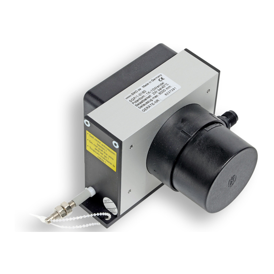
Federgehäuse Abb. 1: Federgehäuse 3 Identifikation Das Typenschild zeigt den Gerätetyp mit Variantennummer. Die Lieferpa- piere ordnen jeder Variantennummer eine detaillierte Bestellbezeichnung z. B. SGP/1 0023 Varianten-Nr. Geräte-Typ SGP/1 · Datum 03.07.2017 · Art. Nr. 84050 · Änd. Stand 206/17... -
Page 6: Installation
Abb. 2: Prüfung Auszugslänge Montage Seilzuggeber (Abb. 1. Entfernen Sie den als Transportsicherung angebrachten Kabelbinder . Zwei Durchgangslöcher dienen zur Befestigung auf einer ebene Montagefläche Kabelbinder Montagefläche Abb. 3: Montage SGP/1 · Datum 03.07.2017 · Art. Nr. 84050 · Änd. Stand 206/17... - Page 7 7) montieren. 3. Nach der Montage mit geöffnetem Seilhaken, Seilhaken wieder schlie- Abb. ßen (siehe Seilhaken Abb. 5: Seilaufnahme mit Haken Abb. 6: Seilhaken geschlossen Abb. 7: Seilhaken geöffnet SGP/1 · Datum 03.07.2017 · Art. Nr. 84050 · Änd. Stand 206/17...
-
Page 8: Elektrische Installation
1. Zum Öffnen des Gerätes den Seilzuggeber mit dem Getriebegehäuse fixieren und die Haube entgegen dem Uhrzeigersinn um eine 1/4 Umdrehung drehen bis der Bajonettverschluss ausrastet. 2. Die Haube axial vom Getriebegehäuse abnehmen. SGP/1 · Datum 03.07.2017 · Art. Nr. 84050 · Änd. Stand 206/17... -
Page 9: Anschlussbelegung
Abb. 9: Schließen 4.4 Anschlussbelegung • 4 pol. Stiftkontakt (M12 A-kodiert) Zubehör Gegenstecker siehe Kapitel 10. Potentiometer ohne Messwandler Belegung Po (Anfangsstellung) Pe (Endstellung) Ansichtseite = S (Schleifer) Steckseite Stiftkontakt SGP/1 · Datum 03.07.2017 · Art. Nr. 84050 · Änd. Stand 206/17... - Page 10 3. Litzen durch die Verschraubung schieben. Kunststoffeinsatz die Verschraubung einpassen. 4. Die Mutter aufschrauben und die komplette Verschraubung (mit O-Ring zur Abdichtung) an der Haube anbringen. SGP/1 · Datum 03.07.2017 · Art. Nr. 84050 · Änd. Stand 206/17...
- Page 11 Abb. 12: Litzenanschluss Schraubklemmenbelegung ohne Messwandler Belegung Klemme Pe (Endstellung) S (Schleifer) Po (Anfangsstellung) Schraubklemmenbelegung mit R/I-Wandler (MWI) Belegung Klemme I+ (4 ... 20 mA) I- (4 ... 20 mA) SGP/1 · Datum 03.07.2017 · Art. Nr. 84050 · Änd. Stand 206/17...
-
Page 12: Lageänderung Kabel- Oder Steckerabgang
~220° gegen den Uhrzeigersinn und ~90° in Richtung des Uhrzeigersinns. 4. Die Innensechskanntschrauben wieder anziehen, Haube aufsetzen und schließen. Innensechskantschrauben Getriebegehäuse Abb. 15: Lageänderung Kabel- oder Steckerabgang SGP/1 · Datum 03.07.2017 · Art. Nr. 84050 · Änd. Stand 206/17... -
Page 13: Einstellung Und Abgleich
10-Wendel-Potentiometer Abb. 16: Einstellen Trimmpotentiometer MWI • Mit Trimmpotentiometer Po kann ein Strom von 4 mA bei Auszugslän- gen von 0 ... 15 % der insgesamt möglichen Auszugslänge eingestellt werden. SGP/1 · Datum 03.07.2017 · Art. Nr. 84050 · Änd. Stand 206/17... -
Page 14: Abgleich Des R/U-Wandlers (Mwu)
Die Ausgangslast sollte jedoch so dimensioniert sein, dass in der Endstel- lung (10 V) ein Ausgangsstrom von 15 mA nicht überschritten wird. Abb. 18) kann dieser Wert an Mit dem Trimmpotentiometer Pe (siehe die tatsächliche Endstellung der Anwendung angepasst werden. SGP/1 · Datum 03.07.2017 · Art. Nr. 84050 · Änd. Stand 206/17... -
Page 15: Was Tun Wenn
20 mA bringen lassen? • Dann ist vermutlich der Verstellbereich des Potentiometers zu klein (Schleifer bewegt sich innerhalb des minimalen Bereichs von 15 ... 90 % und überstreicht einen zu kleinen Widerstandsbereich). SGP/1 · Datum 03.07.2017 · Art. Nr. 84050 · Änd. Stand 206/17... -
Page 16: Inbetriebnahme
• einwandfreie Montage des Geräts. 8 Verfahrgeschwindigkeiten (mm/s) Messbereich [mm] Verfahrgeschwindigkeit [mm/s] ≤200 1000 ≤300 1250 ≤300 1500 ≤400 1750 ≤490 2000 ≤500 2250 ≤600 2500 ≤700 2750 ≤800 3000 ≤800 SGP/1 · Datum 03.07.2017 · Art. Nr. 84050 · Änd. Stand 206/17... -
Page 17: Transport, Lagerung, Wartung Und Entsorgung
Stoffe und sind zugleich Wertstoffträger. Der Seilzuggeber muss deshalb nach seiner endgültigen Stilllegung einem Recycling zuge- führt werden. Die Umweltrichtlinien des jeweiligen Landes müssen hierzu beachtet werden. SGP/1 · Datum 03.07.2017 · Art. Nr. 84050 · Änd. Stand 206/17... -
Page 18: Zubehör
• Zubehör SIKO Art. Nr. "UR". Wenn das Seil nicht lotrecht zum Seilausgang befestigt werden kann, ermöglicht der Einsatz einer Umlenkrolle den Auszug in jede beliebige Richtung. SGP/1 · Datum 03.07.2017 · Art. Nr. 84050 · Änd. Stand 206/17... -
Page 19: Gegenstecker M12 Gerade
Mechanische Daten Ergänzung Gehäuse Aluminium/Kunststoff Seiltyp Stahlseil (Edelstahl rostfrei) ø0.54 mm Stahlseil (Edelstahl rostfrei) kunststoffummantelt ø0.87 mm Paraleine ø1.05 mm Auszugskraft ≥8 N Messweg/ Seiltromme- 200 mm lumdrehung Beschleunigung ≤23.5 m/s² Gewicht ~0.7 kg SGP/1 · Datum 03.07.2017 · Art. Nr. 84050 · Änd. Stand 206/17... - Page 20 Ergänzung Wiederholgenauigkeit ~0.5 mm je Anfahrtsrichtung Messbereich 3600° +10° Verfahrgeschwindigkeit siehe Tabelle Umgebungsbedingungen Ergänzung Umgebungstemperatur -20 … 80 °C -40 … 80 °C T2 (Einzugsgeschwindigkeit ≤800 mm/s) Schutzart IP65 (Potentiometerteil) EN 600529 SGP/1 · Datum 03.07.2017 · Art. Nr. 84050 · Änd. Stand 206/17...
- Page 21 7 Commissioning 8 Travel speeds (mm/s) 9 Transport, Storage, Maintenance and Disposal 10 Accessory 10.1 Wire extension 10.2 Guide roller 10.3 Straight mating connector M12 11 Technical data SGP/1 · Date 03.07.2017 · Art. No. 84050 · Mod. status 206/17...
-
Page 22: Documentation
Danger that may cause minor injury, property damage or unplanned device CAUTION reactions if you disregard the instructions given. SGP/1 · Date 03.07.2017 · Art. No. 84050 · Mod. status 206/17... -
Page 23: Target Group
Spiral spring jumping out DANGER Injuries such as cuts caused by the prestressed spiral spring jumping out. ` Do not open the spring casing of the wire-actuated encoder (see Fig. SGP/1 · Date 03.07.2017 · Art. No. 84050 · Mod. status 206/17... -
Page 24: Identification
` The wire must not spring back losely, it must be stressed by spring force in every situation and movement. Destruction of the wire-actuated encoder WARNING ` Do not extend the wire beyond the specified maximum extension Fig. length (see SGP/1 · Date 03.07.2017 · Art. No. 84050 · Mod. status 206/17... - Page 25 2. Mount the wire accommodation using the lock nut and the set- ting nut Wire accommodation Lock nut Setting nut Fig. 4: Wire accommodation with thread SGP/1 · Date 03.07.2017 · Art. No. 84050 · Mod. status 206/17...
-
Page 26: Electrical Installation
When mounting the system keep a maximum possible distance from lines loaded with interference. If necessary, provide additional installations including screening shields or metallized housings. SGP/1 · Date 03.07.2017 · Art. No. 84050 · Mod. status 206/17... -
Page 27: How To Open And Close The Device
Hood Gear's housing axially close clockwise-rotating Fig. 9: Closing SGP/1 · Date 03.07.2017 · Art. No. 84050 · Mod. status 206/17... -
Page 28: Pin Assignment
1. Prepare wire accord. to Fig. 2. Open the device (see chapter 4.3) and unscrew the PG-screws. Shink sleeve Ferrule Wire cross section: 2x 0.25 mm² or 3x 0.25 mm² Fig. 10: Cable preparation SGP/1 · Date 03.07.2017 · Art. No. 84050 · Mod. status 206/17... - Page 29 6. Close the geared potentiometer (see chapter 4.3). Screw connector Fig. 12: Wire connection Screw connector connection without instrument transformer Designation Terminal Pe (End point) S (Moving contact) Po (Start point) SGP/1 · Date 03.07.2017 · Art. No. 84050 · Mod. status 206/17...
-
Page 30: Changing The Position Of Cable Or Connector Outlet
3. Now you can rotate the drive's housing , ~220° counter-clockwise and ~90° clockwise. 4. Tighten the Allen screws , put the hood on the device and close it. SGP/1 · Date 03.07.2017 · Art. No. 84050 · Mod. status 206/17... -
Page 31: Adjustment And Alignment
(completely pulled out). Fig. 16) these values Via two trim potentiometers Pe and Po (see can be adjusted to the application's actual start and end position. SGP/1 · Date 03.07.2017 · Art. No. 84050 · Mod. status 206/17... - Page 32 20 mA is measured. The steps 1 to 4 are to be repeated until the values are counterbalanced (iterative alignment). Current (Pe) 20 mA (Po) 4 mA Distance Fig. 17: Aligment SGP/1 · Date 03.07.2017 · Art. No. 84050 · Mod. status 206/17...
-
Page 33: Alignment Of The R/U Transformer (Mwu)
• An output voltage of 10 V with an extension position of 60 to 100 % of the maximum encoder extension length can be set. Alignment 1. Move axis to end position. 2. Turn potentiometer Pe until an output voltage 10 V is measured. SGP/1 · Date 03.07.2017 · Art. No. 84050 · Mod. status 206/17... -
Page 34: What To Do If
Please ensure that the instructions given in chapter regarding mechanical and electrical connection are followed. This will ensure correct installation and the operating reliability of the device. Before starting check again: • correct polarity of the supply voltage. • correct cable connection. • correct mounting of the device. SGP/1 · Date 03.07.2017 · Art. No. 84050 · Mod. status 206/17... -
Page 35: Travel Speeds (Mm/S)
With correct installation according to chapter the wire-actuated encoder requires no maintenance. The wire-actuated encoder has received life- time lubrication and need not be lubricated under normal operating con- ditions. SGP/1 · Date 03.07.2017 · Art. No. 84050 · Mod. status 206/17... -
Page 36: Accessory
2. Press clamping sleeve into connection piece and screw connec- tion in order to connect form-fit both pieces. Screw connector Connecting piece Clamping sleeve Fig. 20: Mounting wire extension SGP/1 · Date 03.07.2017 · Art. No. 84050 · Mod. status 206/17... -
Page 37: Guide Roller
3. Dismantle cable, strip and tin conductor. (according to chapter 4.4). 4. Screw wires into socket 5. Mount parts 6. Screw pressing screw and coupling sleeve together. Fig. 21: Straight mating connector M12 SGP/1 · Date 03.07.2017 · Art. No. 84050 · Mod. status 206/17... -
Page 38: Technical Data
Electrical data Transducer, voltage output Additional information Operating voltage 15 … 28 V DC at 3 mA without load Output voltage 0 … 10 V DC Resistance 2 … 10 kΩ against GND Load ≤15 mA SGP/1 · Date 03.07.2017 · Art. No. 84050 · Mod. status 206/17... - Page 39 3600° +10° Travel speed see table Ambient conditions Additional information Ambient temperature -20 … 80 °C -40 … 80 °C T2 (draw-in speed ≤800 mm/s) Protection category IP65 (potentiometer part) EN 600529 SGP/1 · Date 03.07.2017 · Art. No. 84050 · Mod. status 206/17...
- Page 40 SIKO GmbH Weihermattenweg 2 79256 Buchenbach Telefon/Phone + 49 7661 394-0 Telefax/Fax + 49 7661 394-388 E-Mail info@siko.de Internet www.siko-global.com Service support@siko.de...
Need help?
Do you have a question about the SGP/1 and is the answer not in the manual?
Questions and answers