Siko SG10 Installation Instructions Manual
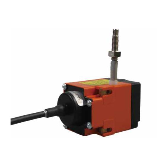
Wire-actuated encoder
Hide thumbs
Also See for SG10:
- User information (12 pages) ,
- Installation instructions manual (20 pages)

Related Manuals for Siko SG10


Summary of Contents for Siko SG10
- Page 1 SG10 Seilzuggeber Deutsch Originalmontageanleitung Seite 2 Wire-actuated Encoder English Translation of the Original Installation Instructions page 16 215/18...
-
Page 2: Table Of Contents
5.3 Abgleich des R/U-Wandlers (MWU) 5.4 Justage Inkrementalgeber (Abb. 6 Inbetriebnahme 7 Transport, Lagerung, Wartung und Entsorgung 8 Zubehör Abb. 8.1 Seilverlängerung (Abb. 8.2 Umlenkrolle 9 Technische Daten SG10 · Datum 18.06.2018 · Art. Nr. 80805 · Änd. Stand 215/18... -
Page 3: Dokumentation
Todesfolge, Sachschäden oder ungeplanten Gerätereaktionen führen können, sofern Sie die gegebenen Anweisungen missachten. Gefährdungen, die zu schweren Körperverletzungen, Sachschäden oder WARNUNG ungeplanten Gerätereaktionen führen können, sofern Sie die gegebenen Anweisungen missachten. SG10 · Datum 18.06.2018 · Art. Nr. 80805 · Änd. Stand 215/18... -
Page 4: Zielgruppe
Automatisierungstechnik vertraut sind; • als Inbetriebnahme- und Monatagepersonal berechtigt sind, Strom- kreise und Geräte/Systeme gemäß den Standards der Sicherheitstech- nik in Betrieb zu nehmen, zu erden und zu kennzeichnen. SG10 · Datum 18.06.2018 · Art. Nr. 80805 · Änd. Stand 215/18... -
Page 5: Grundlegende Sicherheitshinweise
Federgehäuse Abb. 1: Federgehäuse 3 Identifikation Das Typenschild zeigt den Gerätetyp mit Variantennummer. Die Lieferpa- piere ordnen jeder Variantennummer eine detaillierte Bestellbezeichnung z. B. SG10 0023 Varianten-Nr. Geräte-Typ SG10 · Datum 18.06.2018 · Art. Nr. 80805 · Änd. Stand 215/18... -
Page 6: Installation
(Befestigungsmaße siehe Datenblatt). 2. Das Seilabschluss-Stück ( ) beziehungsweise das Seil bis an die vorgesehene Befestigungsstelle ausziehen. 3. Die Seilaufnahme mit Hilfe der Kontermutter und der Einstell- mutter montieren. SG10 · Datum 18.06.2018 · Art. Nr. 80805 · Änd. Stand 215/18... -
Page 7: Elektrische Montage
Zulässige Leistungsaufnahme ACHTUNG Die Versorgung für den Seilzuggeber ist ausreichend zu dimensionieren. Die Spannungswerte sind abhängig von der Geräteausführung und sind den technischen Daten in Kapitel zu entnehmen. SG10 · Datum 18.06.2018 · Art. Nr. 80805 · Änd. Stand 215/18... - Page 8 Der Messwandler liefert eine Ausgangsspannung im Bereich von 0 ... 10 V DC. Farbe Belegung weiß grün Uout braun +24 V DC Anschlussbelegung Inkrementalgeber Angaben zu den elektrischen Anschlüssen sind der Dokumentation des Inkrementalgebers zu entnehmen. SG10 · Datum 18.06.2018 · Art. Nr. 80805 · Änd. Stand 215/18...
-
Page 9: Einstellung Und Abgleich
Trimmpotentio- meter Po Abb. 6: Einstellen Trimmpotentiometer MWI • Mit Trimmpotentiometer Po kann ein Strom von 4 mA bei Potentiome- terwerten von 0 ... 15 % des Gesamtwertes eingestellt werden. SG10 · Datum 18.06.2018 · Art. Nr. 80805 · Änd. Stand 215/18... -
Page 10: Abgleich Des R/U-Wandlers (Mwu)
Der Messwandler ist bei Auslieferung abgeglichen. Anfangsstellung 0 V Ausgangsspannung (Po), entspricht Auszugslänge 0 mm (vollständig ein- gezogen). Endwert 10 V Ausgangsspannung (Pe), entspricht der maxima- len Auszugslänge des Gebers (vollständig ausgezogen). SG10 · Datum 18.06.2018 · Art. Nr. 80805 · Änd. Stand 215/18... -
Page 11: Justage Inkrementalgeber
Inkrementalgeber drehen lässt. 3. Den Geber gegen den Uhrzeigersinn drehen (in Pfeilrichtung), bis der Referenzpunkt erreicht ist. 4. Schrauben anziehen. 5. Gehäusedeckel schließen und mit Schrauben befestigen. SG10 · Datum 18.06.2018 · Art. Nr. 80805 · Änd. Stand 215/18... -
Page 12: Inbetriebnahme
Beschädigte Seilzuggeber nicht einbauen. Wartung Bei korrektem Einbau nach Kapitel ist der Seilzuggeber wartungsfrei. Der Seilzuggeber enthält eine Lebensdauerschmierung und muss unter norma- len Betriebsbedingungen nicht nachgeschmiert werden. SG10 · Datum 18.06.2018 · Art. Nr. 80805 · Änd. Stand 215/18... -
Page 13: Zubehör
Schraubverbindung stecken. 2. Spannhülse in Anschlussstück und Schraubverbindung pres- sen, so werden beide Teile formschlüssig verbunden. Schraubverbindung Anschlussstück Spannhülse Abb. 11: Montage Seilverlängerung SG10 · Datum 18.06.2018 · Art. Nr. 80805 · Änd. Stand 215/18... -
Page 14: Umlenkrolle
Elektrische Daten Geber Potentiometer Ergänzung Belastbarkeit 1.5 W bei 70 °C Widerstand 10 kΩ Widerstandstoleranz ±5 % Standard-Endwiderstand ≤0.5 % oder 1 Ω (es gilt jeweils der größere Wert) Linearitätstoleranz ±0.25 % ±0.1 % Gebertyp MWI/0,1 SG10 · Datum 18.06.2018 · Art. Nr. 80805 · Änd. Stand 215/18... - Page 15 Messwandler relative Luftfeuchtigkeit Betauung nicht zulässig EN 61000-6-2 Störfestigkeit / Immission EN 61000-6-4 Störaussendung / Emission Schutzart IP50 (Geberteil Potentiome- EN 600529 ter) IP54 (Inkremental) EN 600529 SG10 · Datum 18.06.2018 · Art. Nr. 80805 · Änd. Stand 215/18...
- Page 16 5.3 Alignment of the R/U transformer (MWU) 5.4 Incremental encoder adjustment (Fig. 6 Commissioning 7 Transport, Storage, Maintenance and Disposal 8 Accessories Fig. 8.1 Wire extension (Fig. 8.2 Guide roller 9 Technical data SG10 · Date 18.06.2018 · Art. No. 80805 · Mod. status 215/18...
-
Page 17: Documentation
Danger that may cause minor injury, property damage or unplanned device CAUTION reactions if you disregard the instructions given. SG10 · Date 18.06.2018 · Art. No. 80805 · Mod. status 215/18... -
Page 18: Target Group
` Take protective measures to prevent people from being grasped. Spiral spring jumping out DANGER Injuries such as cuts caused by the prestressed spiral spring jumping out. Fig. ` Do not open the wire-actuated encoder (see SG10 · Date 18.06.2018 · Art. No. 80805 · Mod. status 215/18... -
Page 19: Identification
` The wire must not spring back losely, it must be stressed by spring force in every situation and movement. Destruction of the wire-actuated encoder WARNING ` Do not extend the wire beyond the specified maximum extension Fig. length (see SG10 · Date 18.06.2018 · Art. No. 80805 · Mod. status 215/18... - Page 20 Screw M4 (not included in the scope of delivery) Wire accommodation Lock nut Setting nut Fig. 3: Mounting/wire end piece SG10 · Date 18.06.2018 · Art. No. 80805 · Mod. status 215/18...
-
Page 21: Electrical Installation
Po (Start point) Pin assignment of the potentiometer with R/I transformer (MWI) (Fig. Fig. The instrument transformer provides a loop current in the range of 4 ... 20 mA. Color Designation white brown SG10 · Date 18.06.2018 · Art. No. 80805 · Mod. status 215/18... -
Page 22: Adjustment And Alignment
The measuring range of the potentiometer is matched to the total pull-out length of the wire. Ex works value 0 Ω is preset for the pull-out length of 0 mm (wire completely pulled in). SG10 · Date 18.06.2018 · Art. No. 80805 · Mod. status 215/18... -
Page 23: Alignment Of The R/I Transformer (Mwi)
3. Move the machine to the end position. 4. Turn potentiometer Pe until end value 20 mA is measured. The steps 1 to 4 are to be repeated until the values are counterbalanced (iterative alignment). SG10 · Date 18.06.2018 · Art. No. 80805 · Mod. status 215/18... -
Page 24: Alignment Of The R/U Transformer (Mwu)
By means of the trim potentiometer Pe (see adjusted to the actual final position of the application. 1. Unscrew the screws and open the cover of the housing 2. Adjust the trim potentiometer Pe SG10 · Date 18.06.2018 · Art. No. 80805 · Mod. status 215/18... -
Page 25: Incremental Encoder Adjustment (Fig. 9)
5. Close the cover of the housing and fasten it by means of screws Screw Cover of the housing Screw Fig. 9: Incremental encoder adjustment SG10 · Date 18.06.2018 · Art. No. 80805 · Mod. status 215/18... -
Page 26: Commissioning
Therefore, the wire-actuated encoder or the rotary encoder must be recycled after it has been taken out of operation ultimately. Observe the environment protection guidelines of your country. SG10 · Date 18.06.2018 · Art. No. 80805 · Mod. status 215/18... -
Page 27: Accessories
Guide rollers are used for applications where wire-actuated encoder and wire cannot be mounted in one line. By using guide rollers the wire can be pulled out in any direction. SG10 · Date 18.06.2018 · Art. No. 80805 · Mod. status 215/18... -
Page 28: Technical Data
Electrical data Transducer, voltage output Additional information Operating voltage 15 … 28 V DC at 3 mA, no load Output voltage 0 … 10 V DC Resistance 2 … 10 kΩ against GND Load ≤15 mA SG10 · Date 18.06.2018 · Art. No. 80805 · Mod. status 215/18... - Page 29 EN 61000-6-2 interference resistance / immis- sion EN 61000-6-4 emitted interference / emission Protection category IP50 (encoder part potenti- EN 600529 ometer) IP54 (incremental) EN 600529 SG10 · Date 18.06.2018 · Art. No. 80805 · Mod. status 215/18...
- Page 30 SG10...
- Page 31 SG10...
- Page 32 SIKO GmbH Weihermattenweg 2 79256 Buchenbach Telefon/Phone + 49 7661 394-0 Telefax/Fax + 49 7661 394-388 E-Mail info@siko.de Internet www.siko-global.com Service support@siko.de...
Need help?
Do you have a question about the SG10 and is the answer not in the manual?
Questions and answers