Table of Contents
Advertisement
Quick Links
Advertisement
Table of Contents

Related Manuals for KYLAND Technology SICOM3028GPT Series


Summary of Contents for KYLAND Technology SICOM3028GPT Series
- Page 1 SICOM3028GPT/3424PT/3028GP/3424P Series Industrial Ethernet Switch Hardware Installation Manual Kyland Technology Co., LTD. Publication Date: Mar. 2012 Version: V1.2 Customer Service Hotline: (+8610) 88796676 FAX: (+8610) 88796678 Website: http://www.kyland.cn E-mail: support@kyland.biz...
- Page 2 SICOM3028GPT/3424PT/3028GP/3424P Series Industrial Ethernet Switch Hardware Installation Manual Disclaimer: Kyland Technology Co., Ltd. tries to keep the content of this manual as accurate and as updated as possible. T his document i s not g uaranteed t o b e error-free, and we reserve the right to amend it without notice to users.
- Page 3 SICOM3028GPT/3424PT/3028GP/3424P User’s Manual-v1.2 Notice for Safety Operation This pr oduct per forms r eliably as long as it is used acc ording t o t he g uidance. Artificial damage or destruction of the equipment should be avoided. Read this manual carefully and keep it for future reference; ...
-
Page 4: Table Of Contents
SICOM3028GPT/3424PT/3028GP/3424P User’s Manual-v1.2 Contents Packing List ......................5 Product Overview ....................5 Structure and Interface ..................6 3.1 Front Panel ....................6 3.2 Rear Panel ....................6 3.2.1 Rear Panel 1U Slot ................7 3.2.2 Rear Panel 0.5U Slot ................. 8 Interface Modules Mounting ................ - Page 5 SICOM3028GPT/3424PT/3028GP/3424P User’s Manual-v1.2 LED Indicators ....................29 Power-on Self-inspection ................. 31 Management Access ..................32 9.1 Connected through Console Port .............. 32 9.2 Connected through Ethernet Cable ............34 9.3 Web Access ....................35 10 Product Configuration Information ..............36 11 Basic Features and Specifications ..............
-
Page 6: Packing List
SICOM3028GPT/3424PT/3028GP/3424P User’s Manual-v1.2 1 Packing List Industrial Ethernet Switch CD (including Hardware Installation Manual, Web Operation Manual and Windows utility) Screwdriver Mounting Bracket Puller Certificate of Quality (including Certificate of Compliance) Note: After unpacking, please check the accessories and the appearance of the equipment. If anything is missing or damaged, please contact us. -
Page 7: Structure And Interface
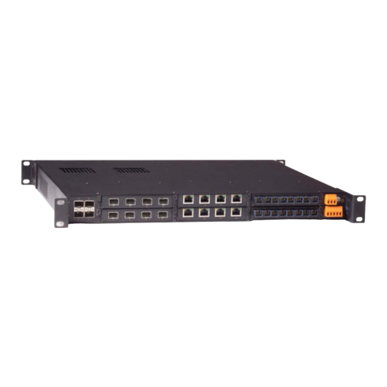
SICOM3028GPT/3424PT/3028GP/3424P User’s Manual-v1.2 3 Structure and Interface 3.1 Front Panel Figure 1 Front Panel 1: Alarm-Alarm LED 2: Run-Running LED 3: Ring-Ring LED 4: Lock-Synchronization Finish LED 5: PWR2-Power 2 LED 6: PWR1-Power 1 LED 7: Slot (1-7) Speed (1-4)-4 port Speed LEDs (Slot (1-7)) 8: Slot (1-7) Link/ACT (1-4)-4 port Link/ACTLEDs ((Slot (1-7)) 9: Console-Console interface (Mini USB) 10: USB interface (for future release) -
Page 8: Rear Panel 1U Slot
SICOM3028GPT/3424PT/3028GP/3424P User’s Manual-v1.2 5: 0.5U Slot5 for 4-port Ethernet interface module 6: 0.5U Slot6 for 4-port Ethernet interface module 7: 0.5U Slot7 for 4-port Ethernet interface module 8: Alarm contact 9: Grounding screw 10: Terminal block for power input 11: Rear mounting bracket 3.2.1 Rear Panel 1U Slot ... -
Page 9: Rear Panel 0.5U Slot
SICOM3028GPT/3424PT/3028GP/3424P User’s Manual-v1.2 3.2.2 Rear Panel 0.5U Slot SM6.6-4GX-0.5U Figure 6 SM6.6-4GX-0.5U SM6.6-4GX-0.5U: 4 1000Base-X, 10/100/1000Base-T(X) SFP ports SM6.6-2GX-2S/M-0.5U Figure 7 SM6.6-2GX-2S/M-0.5U SM6.6-2GX-2S/M-0.5U: 2 1000Base-X, 10/100/1000Base-T(X) SFP ports 2 100Base-FX, SM/MM ports, FC/SC/ST connector SM6.6-4GE-0.5U Figure 8 SM6.6-4GE-0.5U SM6.6-4GE-0.5U: 4 10/100/1000Base-T(X) RJ45 ports ... -
Page 10: Interface Modules Mounting
SICOM3028GPT/3424PT/3028GP/3424P User’s Manual-v1.2 2 1000Base-X, 10/100/1000Base-T(X) SFP ports 2 10/100/1000Base-T(X) RJ45 ports SM6.6-4S/M-0.5U Figure 10 SM6.6-4S/M-0.5U SM6.6-4S/M-0.5U: 4 100Base-FX, SM/MM ports, FC/SC/ST connector SM6.6-2S/M-2T-0.5U Figure 11 SM6.6-2S/M-2T-0.5U SM6.6-2S/M -2T-0.5U: 2 100Base-FX, SM/MM ports, FC/SC/ST connector 2 10/100Base-T(X) RJ45 ports ... -
Page 11: Interface Modules Mounting
SICOM3028GPT/3424PT/3028GP/3424P User’s Manual-v1.2 4.1 Interface Modules Mounting The series switches provide one 1U Slot (Slot1) and six 0.5U Slots (Slot2-Slot7) in the rear panel as shown in Figure 2. Interface modules can be installed into slots as needed. The models of the interface modules are shown in Table 11. Note: Not all the slots need to be installed with the interface modules;... - Page 12 SICOM3028GPT/3424PT/3028GP/3424P User’s Manual-v1.2 Figure 14 0.5U Interface Module Mounting 2 0.5U interface modules installation in lower slots(Slot3,Slot5 and Slot7) Step 1: C hoose the a ppropriate 0 .5U i nterface module. Insert the i nterface module with the port numbers (1, 2, 3, 4) upside down. Insert the guide rail of interface module into the guide rail slot, as shown in Figure 15, and then push the interface module into the slot completely along the guide rail slot.
-
Page 13: Interface Modules Removal
SICOM3028GPT/3424PT/3028GP/3424P User’s Manual-v1.2 (M2.5×5), as shown in Figure 16 . Figure 16 0.5U Interface Module Mounting 4 1U interface modules mounting in Slot1 The installation instructions for 1U interface modules in Slot1 are the same as in upper slots (Slot2, Slot4 and Slot6). Please refer to the instructions above. 4.2 Interface Modules Removal ... - Page 14 SICOM3028GPT/3424PT/3028GP/3424P User’s Manual-v1.2 Step 1: Remove the two fastening screws of the interface module and switch chassis. Step 2: Insert the long tab into the handle of the interface module, as shown in Figure 18; then move the puller left to ensure adequate space for inserting the short tab.
- Page 15 SICOM3028GPT/3424PT/3028GP/3424P User’s Manual-v1.2 Figure 19 Interface Modules Removal 2 Figure 20 Interface Modules Removal 3 Step 4: Grip the handle of puller; push the handle in the direction of arrow 1 with y our t humb, an d at t he sa me t ime pull the handle out wards with your fingers in the direction of arrow 2.
- Page 16 SICOM3028GPT/3424PT/3028GP/3424P User’s Manual-v1.2 Figure 21 Interface Modules Removal 4 Note: When using the puller, ensure to insert the long tab into the handle of the interface module first and then insert the short tab; otherwise the long and s hort tabs will not be inserted into the handles because of the specific design of the puller.
-
Page 17: Switch Chassis Mounting
SICOM3028GPT/3424PT/3028GP/3424P User’s Manual-v1.2 Figure 22 Interface Modules Removal 5 5 Switch Chassis Mounting 5.1 Dimension Drawing... -
Page 18: Mounting Steps
SICOM3028GPT/3424PT/3028GP/3424P User’s Manual-v1.2 Figure 23 Mounting Dimension Drawing Note: The switch housing is part of the heat dissipation system, which becomes hot during operation. Please use caution when coming in contact and avoid covering the ventilation holes of the switch housing when the switch is operating. 5.2 Mounting Steps The series switches support rack mounting by its front/rear panel. - Page 19 SICOM3028GPT/3424PT/3028GP/3424P User’s Manual-v1.2 Step 1: Select the mounting position for the switch in the rack and ensure that there is adequate space for it. Step 2: As shown in Figure 24, move the switch in the direction of arrow 1 and align the holes in the switch mounting brackets and the corresponding holes in the rack;...
-
Page 20: Cable Connection
SICOM3028GPT/3424PT/3028GP/3424P User’s Manual-v1.2 there is adequate space for it. Step 2: As shown in Figure 26, move the switch in the direction of arrow 1 and align the holes in the mounting brackets and the corresponding holes in the rack; use 4 screws (M5×14) to fix the switch in the rack. Figure 26 Mounting by Rear Panel ... - Page 21 SICOM3028GPT/3424PT/3028GP/3424P User’s Manual-v1.2 Pin definition of 10/100Base-T(X) RJ45 port Pin number of 10/100Base-T(X) RJ45 port is shown in Figure 28 Figure 28 RJ45 Port Pin definition of 10/100Base-T(X) RJ45 port is shown in Table 2 Table 2 Pin Definition of 10/100Base-T(X) RJ45 Port MDI-X Signal Name MDI Signal Name Receive Data+(RD+)
-
Page 22: 100Base-Fx Ethernet Port
SICOM3028GPT/3424PT/3028GP/3424P User’s Manual-v1.2 Figure 30 10/100M Cross-over Cable Wiring 6.2 100Base-FX Ethernet Port 100Base-FX Ethernet port is equipped with FC/SC/ST connector, and each port consists of TX (transmit) port and RX (receive) port, as shown on the left in Figure 100Base-FX port wiring is shown on the right in Figure 31 (Take SC port as example;... -
Page 23: 10/100/1000Base-T(X) Ethernet Port
SICOM3028GPT/3424PT/3028GP/3424P User’s Manual-v1.2 Note: A laser is used to transmit signals in fiber cables. The laser meets the requirements of level 1 laser products. Routine operation is not harmful to your eyes, but do not look directly at the fiber port or fiber connector when the switch is powered on. 6.3 10/100/1000Base-T(X) Ethernet Port 10/100/1000Base-T(X) E thernet R J45 por t can be co nnected t o t erminal equipment and network devices with straight-through cables or crossover cables. -
Page 24: 1000Base-X, 10/100/1000Base-T(X) Sfp Port
SICOM3028GPT/3424PT/3028GP/3424P User’s Manual-v1.2 Note: “+”“-”means level polarity. Wiring Sequence Figure 33 10/100/1000M Straight-through Cable Wiring Figure 34 10/100/1000M Cross-over Cable Wiring 6.4 1000Base-X, 10/100/1000Base-T(X) SFP Port 1000Base-X, 10/ 100/1000Base-T(X) S FP p ort na mely i s 1000Base S FP sl ot. Insert SFP module to SFP slot, and then plug twisted pair or optical fiber into SFP module t o t ransmit d ata. - Page 25 SICOM3028GPT/3424PT/3028GP/3424P User’s Manual-v1.2 Figure 35 Gigabit SFP Optical Module Gigabit S FP op tical module is equipped w ith LC c onnector, an d each por t consists of TX (transmit) port and R X (receive) port, as shown on the left in Figure 36.
-
Page 26: Gigabit Sfp Electrical Module
SICOM3028GPT/3424PT/3028GP/3424P User’s Manual-v1.2 2. Check the corresponding port Link/ACT indicator in the front panel: Indicator flashing means link connectivity; Indicator o ff means no l ink connectivity and i t may be b ecause of the incorrect link between RX port and TX port in SFP optical modules. Try to swapping connectors in any one end of optical fiber. -
Page 27: Console Interface
SICOM3028GPT/3424PT/3028GP/3424P User’s Manual-v1.2 Figure 39 SFP Electrical Module 6.5 Console Interface Install the driver for Mini USB onto your PC. The driver “Mini USB driver.exe” is in the so ftware d ownload folder, w hich i s on the s upplied C D. Connect the U SB port on t he P C to t he Console interface on the switch with cable equipped with Mini U SB co nnector and U SB c onnector at b oth ends. -
Page 28: Power
SICOM3028GPT/3424PT/3028GP/3424P User’s Manual-v1.2 USB connector pin number is shown in Figure 41. Figure 41 USB Connector USB pin definition is shown in Table 5. Table 5 USB Pin Definition USB Pin Definition VBUS 6.6 Power According to the power input requirements, use a 5.08mm-spacing terminal block to connect power cable. -
Page 29: Grounding
SICOM3028GPT/3424PT/3028GP/3424P User’s Manual-v1.2 Protection Ground Protection Ground PWR2: - PWR2: N PWR2: + PWR2: L Wiring and mounting Step 1: Take the power terminal block off the switch. Step 2: Insert the power cable into the terminal block and connect the power cable. -
Page 30: Relay Contact
SICOM3028GPT/3424PT/3028GP/3424P User’s Manual-v1.2 Note: T he cr oss section ar ea of c hassis grounding ca ble sh ould b e m ore t han 2. 5mm . T he grounding resistance requirement: <5Ω. 6.8 Relay Contact The relay contact is used for alarm output. When the switch works normally, the normally-open co ntact of t he al arm r elay is closed a nd t he n ormally-closed contact is open;... - Page 31 SICOM3028GPT/3424PT/3028GP/3424P User’s Manual-v1.2 Table 7 SICOM3028GPT/3424PT/3028GP/3424P Front Panel LEDs State Description System Running LED CPU operates abnormally or the switch is in the power on and startup process Blinking CPU operates normally (1Hz) CPU does not start up Alarm LED Blinking System alarm (5Hz)
-
Page 32: Power-On Self-Inspection
SICOM3028GPT/3424PT/3028GP/3424P User’s Manual-v1.2 1000M working state 1000Base-X 100M working state or no connection 100M working state 10/100Base-T(X) 10M working state or no connection 100M working state 100Base-FX no connection Effective network connection in the port Link/ACT Blinking Network activities in the port No effective network connection in the port Table 8 SICOM3028GPT/3424PT/3028GP/3424P Rear Panel LEDs State... -
Page 33: Management Access
SICOM3028GPT/3424PT/3028GP/3424P User’s Manual-v1.2 proving that the corresponding ports are operating normally. 9 Management Access Access the switch by one of the following three ways. 9.1 Connected through Console Port 1. Install the driver for Mini USB onto your PC. The driver “Mini USB driver.exe” is in the software download folder, which is on the supplied CD. - Page 34 SICOM3028GPT/3424PT/3028GP/3424P User’s Manual-v1.2 Figure 46 New Connection 5. Select COM port as the connection type. Figure 47 Choose Port 6. Set the parameters of COM port (Bits per second: 115200, Data bits: 8, Parity: None, Stop bits: 1, Flow control: None)
-
Page 35: Connected Through Ethernet Cable
SICOM3028GPT/3424PT/3028GP/3424P User’s Manual-v1.2 Figure 48 Set COM Parameters 7. Click “OK” to enter the CLI interface, and type in a CLI command from Table 9. Table 9 CLI Command View Command Description User View SWITCH>enable Enter management view SWITCH#show i nterface Show t he default IP addr ess of cu rrent Management View... -
Page 36: Web Access
SICOM3028GPT/3424PT/3028GP/3424P User’s Manual-v1.2 Figure 49 Enter Telnet 3. Click “OK”, and input a default user name “admin” and password “123” to enter the Telnet configuration interface, see Figure 50.Type in a CLI command from Table 9. Figure 50 Telnet Configuration Interface 9.3 Web Access 1. -
Page 37: Product Configuration Information
SICOM3028GPT/3424PT/3028GP/3424P User’s Manual-v1.2 Figure 51, login with default user name “admin” and password “123”. Figure 51 Access Web Interface 10 Product Configuration Information Table 10 SICOM3028GPT/3424PT/3028GP/3424P Chassis Table Slot Model Power 0.5U Slot 1U Slot SICOM3028GPT-Chassis 24DC,48DC, SICOM3424PT-Chassis 220AC/DCW SICOM3028GP-Chassis redundant SICOM3424P-Chassis Table 11 SICOM3028GPT/3424PT/3028GP/3424P Interface Modules... - Page 38 SICOM3028GPT/3424PT/3028GP/3424P User’s Manual-v1.2 0.5 interface module, supports 2 Only SICOM3028GPT, 1000Base-X,10/100/1000Base-T(X)SFP ports; 2 SM6.6-2GX-2GE-0.5U SICOM3028GP 10/100/1000Base-T(X) RJ45 ports 0.5U interface module, supports 4 For al l pr oduct SM6.6-4S/M-0.5U 100Base-FX,SM/MM ports, FC/SC/ST connector models 0.5U interface module, supports 2 For al l pr oduct 100Base-FX,SM/MM ports, FC/SC/ST connector SM6.6-2S/M -2T-0.5U models...
-
Page 39: Basic Features And Specifications
SICOM3028GPT/3424PT/3028GP/3424P User’s Manual-v1.2 Model Description DT-FCZ-RJ45-01 RJ45 dustproof shield DT-XL-Mini USB-USB-2m USB console cable, Mini USB to USB, 2m Gigabit SFP Module IGSFP-TX-RJ45 10/100/1000Base-T(X) RJ45 port; transmission distance is 100m IGSFP-M-SX-LC-850-0.55 1000Base-X port; multi mode, LC connector; wavelength is 850nm, transmission distance is 550m IGSFP-S-LX-LC-1310-10 1000Base-X port;... - Page 40 SICOM3028GPT/3424PT/3028GP/3424P User’s Manual-v1.2 Dimensions (W×H×D): 482.6mm×44mm×360mm Weight: <10Kg( 22.046 pound) Environment Limits Operating Temperature: -40℃ to 85℃ Storage Temperature: -40℃ to 85℃ Ambient Relative Humidity: 5% to 95% (non-condensing) MTBF SICOM3028GPT/3424PT: 359000h SICOM3028GP/3424P: 360000h Warranty 5 years For more information about KYLAND products, please visit our website: http://www.kyland.cn/...
Need help?
Do you have a question about the SICOM3028GPT Series and is the answer not in the manual?
Questions and answers