Sign In
Upload
Manuals
Brands
Rosslare Manuals
Control Panel
AuraSys L-4PCBA
Rosslare AuraSys L-4PCBA Manuals
Manuals and User Guides for Rosslare AuraSys L-4PCBA. We have
2
Rosslare AuraSys L-4PCBA manuals available for free PDF download: Hardware Installation Manual, User Manual
Rosslare AuraSys L-4PCBA Hardware Installation Manual (74 pages)
Brand:
Rosslare
| Category:
Control Panel
| Size: 3.65 MB
Table of Contents
Table of Contents
3
1 Introduction
9
Figure 1: Rosslare L-4 Panel
10
Figure 2: Rosslare L-4K Panel
10
Figure 3: Rosslare L-4 PCBA Panel
11
Figure 4: Rosslare L-4C, L-4CL, and L-4CU Panels
11
Figure 5: Rosslare L-4D, L-4DL, and L-4DU Panels
12
2 Technical Specifications and Features
13
Mechanical Specifications
15
3 Installation and Wiring
16
Installation Quick Guide
16
Installation Prerequisites
16
Preparing the Installation Environment
16
Preparing the Wiring
16
Mounting the Control Panel
17
Figure 6: L-4 PCBA Panel Mounting Holes
17
Figure 7: L-4C Mounting Template
18
Figure 8: L-4C Mounting
19
Figure 9: L-4D Mounting Template
20
Figure 10: L-4D Mounting
21
Installing the Keypad(S)
22
Figure 11: L-4/4K Drilling Template
22
Figure 12: Keypad Mounting Dimensions Kx-04
23
4 Wiring Instructions
24
Wiring Quick Reference
24
Figure 13: L-4/L-4K Control Panel Components
24
Figure 14: L-4 PCBA Control Panel Components and Dimensions
25
Figure 15: L-4C Casing Wiring Threads
26
Wiring the System
27
AC Wiring
27
Battery Connection
27
Figure 16: L-4D Casing Wiring Threads
27
Telephone Wiring
28
Keypad and Expansion Wiring
28
PGM Connection
28
Figure 17: Battery Connection Diagram
28
Figure 18: Telephone Diagram
28
Smoke Detector Connections
29
Figure 19: PGM Wiring Diagram
29
Figure 20: Smoke Detectors Without Reset Mechanism
30
Zone Wiring
31
Figure 21: Smoke Detectors with Reset Mechanism
31
Table 1: Hardwiring Schematics for Single Zone System
32
Table 2: Hardwiring Schematics for Doubled Zone System
32
Figure 22. Resistors
33
Sounder Connections
34
Figure 23: L-4/L-4K Sounder (Bell) Connection
34
Table 3: Resistor Color Scheme
34
Table 4: Resistors Provided
34
Preliminary Testing
35
5 Programming Via Keypad
36
Keypad Quick Reference
36
Figure 24: KE-04 - Matrixbus™ 4 Zone LED Keypad
36
Keypad User Functions
37
Figure 25: KC-04 - Matrixbus™ 4-Zone LCD Keypad
37
Figure 26: KD-04 - Matrixbus™ 4-Zone Dot-Matrix Keypad
37
Table 5: User Function Buttons
37
Indicator Bar
38
Numeric Programming Pad
38
Table 6: Operational Indicators
38
Figure 27: Numeric Keypad with Programming Icons
39
Table 7: Programming Function Buttons
39
System Audio Feedback
40
Access Level Types
41
Master Programmer
41
Installer Level
41
User
42
Entering Programming Mode (Installer/Master)
42
Enable Installer Code Access
42
Installer Programming Level
42
Entering Parameters
43
General Procedural Steps
43
Programming Tables
43
Advanced System Programming
48
Zone Definitions - Advanced
50
Panel Setup
52
CMS and Private Phone Reporting
52
PGM Setup
55
System Timers
56
Wireless Device Enrollment/Deletion
56
Remote Control Assignment
58
Wireless Siren Definition
58
Walk Test
59
System Time and Date
59
Factory and Access Code Defaults
59
Master/User Access
59
User Codes
59
Duress Code
60
Master User
60
Users Authorization Setup
60
System Time and Date
60
Factory and Access Code Defaults
61
6 Programming Via PC Software
62
Connections
62
Software Programming Options
62
Figure 28: Rosslare's MD-62 TTL to RS-232 Converter
62
Expansions and Accessories
63
RJ-31X Jack)
63
Figure 29: MD-31 Dimensions
63
Figure 30: MD-31 Internal Wiring
63
A.1 MD-31 (RJ-31X Jack)
63
SA-59 GSM Communicator
64
Figure 31: MD-31 to Alarm Panel Wiring
64
A.2 SA-59 GSM Communicator
64
XR-16A - Wireless Expansion
65
Figure 32: SA-59 Universal GSM Communicator
65
A.3 XR-16A – Wireless Expansion
65
Figure 33: XR-16A Wireless Expansion
66
Reporting Codes
67
Table 8: Event Codes: Contact ID - Burglary and Fire
67
Table 9: Event Codes: Contact ID - Arming Events
67
Table 10: Event Codes: Contact ID - System Events
67
Battery Load Capacity
69
Programming Worksheets
70
Customer Information
70
Installer Information
70
Device Information
70
Zone Worksheet
71
D.4 Zone Worksheet
71
Declaration of Conformity
72
Limited Warranty
73
Advertisement
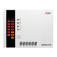
Rosslare AuraSys L-4PCBA User Manual (35 pages)
4-/8-Zone Alarm Panel
Brand:
Rosslare
| Category:
Security System
| Size: 1.17 MB
Table of Contents
System Features
8
System Installation
8
System Technical Specifications
9
About Everyday Operation
11
About the KE-06/KE-04
12
Keypad User Functions
13
Indicators Bar
14
Numeric Programming Pad
15
Audible Indicators
16
Operational Modes
17
User Modes
18
User
19
Entering Master Programming Parameters
20
Alarm Mode
22
Arming Options
23
System Instant Arming Mode
24
System Away Mode
25
Perimeter Arming
26
Siren
27
Controlling Appliances
28
Entering the Duress Code
29
Trouble Status View
30
A. Programming Worksheets
31
A.4 Zone Worksheet
32
Limited Warranty
33
Advertisement
Related Products
Rosslare AuraSys L-4
Rosslare AuraSys L-4K
Rosslare AuraSys L-2
Rosslare AuraSys L-2K
Rosslare AC-215 B Series
Rosslare AC-215-Bx
Rosslare AC-215-DIN
Rosslare AC-215IP-Bx
Rosslare AC-215IP-DIN
Rosslare AC-225-B Series
Rosslare Categories
Card Reader
Controller
IP Access Controllers
Gateway
Security Sensors
More Rosslare Manuals
Login
Sign In
OR
Sign in with Facebook
Sign in with Google
Upload manual
Upload from disk
Upload from URL