Table of Contents
Advertisement
SITOP power supply
Selectivity modules
Manual
SITOP select 4 x 10 A
6EP1961-2BA00
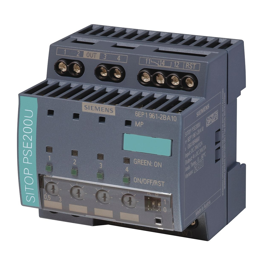
SITOP PSE200U 4 x 3 A
6EP1961-2BA11
6EP1961-2BA31
6EP1961-2BA51
6EP1961-2BA61
SITOP PSE200U 4 x 10 A
6EP1961-2BA21
6EP1961-2BA41
01.2017
C98130-A7579-A1-2-7629
___________________
Overview
___________________
Safety notes
___________________
Description, device design,
dimension drawing
___________________
Mounting/removal
___________________
Mounting position, mounting
clearances
___________________
Installation
___________________
Technical data
___________________
Safety, approvals, EMC
___________________
Environmental conditions
___________________
Environment
___________________
Service & Support
1
2
3
4
5
6
7
8
9
10
Advertisement
Table of Contents

Related Manuals for Siemens SITOP


Summary of Contents for Siemens SITOP
- Page 1 Technical data ___________________ Safety, approvals, EMC ___________________ Environmental conditions ___________________ Environment ___________________ Service & Support SITOP select 4 x 10 A 6EP1961-2BA00 SITOP PSE200U 4 x 3 A 6EP1961-2BA11 6EP1961-2BA31 6EP1961-2BA51 6EP1961-2BA61 SITOP PSE200U 4 x 10 A 6EP1961-2BA21 6EP1961-2BA41 01.2017...
-
Page 2: Legal Information
Note the following: WARNING Siemens products may only be used for the applications described in the catalog and in the relevant technical documentation. If products and components from other manufacturers are used, these must be recommended or approved by Siemens. Proper transport, storage, installation, assembly, commissioning, operation and maintenance are required to ensure that the products operate safely and without any problems. -
Page 3: Overview
Overview Description In conjunction with a 24 V power supply, the selectivity module is used to distribute the load current across several branches and to monitor the individual currents in these branches. Faults in the individual branches caused by overload or short-circuit are detected and selectively switched off, so that the fault does not impact the other load circuits. - Page 4 Ordering data The following device options are available: Selectivity modules Type Order number SITOP select 6EP1961-2BA00 24 V DC input Number of outputs: 4 Setting range of the response threshold: 2 - 10 A with group signal contact SITOP PSE200U...
- Page 5 Overview Accessories Type Order number Flat insertable fuse: Manufacturer, Littelfuse, series FKS, 162.6185.* (FKS-32), 166.7000.* (FKS-80) 19 mm long (for 6EP1961-2BA00) Device identification label 20 mm × 7 mm, pastel turquoise 3RT1900-1SB20 3RT1900-1SB20 (for 6EP1961-2BA11, -2BA21, -2BA31, - 2BA41, -2BA51, -2BA61) Selectivity modules Manual, 01.2017, C98130-A7579-A1-2-7629...
- Page 6 Overview Selectivity modules Manual, 01.2017, C98130-A7579-A1-2-7629...
-
Page 7: Table Of Contents
Connections and terminal designation..................12 Potentiometer .......................... 14 Status displays and signaling ....................15 Buttons and selector switches ....................19 2.5.1 SITOP select ........................... 19 2.5.2 SITOP PSE200U ........................20 Electronic overload shutdown and reset ................. 21 2.6.1 SITOP select ........................... 21 2.6.2... - Page 8 Table of contents Mechanical system ........................ 51 Accessories ..........................52 Dimension drawing ........................ 53 Safety, approvals, EMC ........................55 Safety ............................. 55 Approvals ..........................55 EMC ............................56 Environmental conditions ........................57 Environment ............................59 Service & Support ..........................61 Selectivity modules Manual, 01.2017, C98130-A7579-A1-2-7629...
-
Page 9: Safety Notes
Safety notes WARNING Correct handling of the devices When operating electrical devices, it is inevitable that certain components will carry dangerous voltages. Therefore, failure to handle the units properly can result in death or serious physical injury as well as extensive property damage. Only appropriately qualified personnel may work on or in the vicinity of this equipment. - Page 10 Safety notes Selectivity modules Manual, 01.2017, C98130-A7579-A1-2-7629...
-
Page 11: Description, Device Design, Dimension Drawing
(SITOP PSE200U). The status of the output is displayed using a multi-color LED for each output. The status of the outputs can be processed via a group signaling contact or via a serial single-channel signal. -
Page 12: Connections And Terminal Designation
The operating status of the device can be processed using the group signal contact or status ④ output (function and contact rating, see Figure 2-4 Operating displays and signaling (SITOP select and SITOP PSE200U) (Page 15)). ④ The remote reset input is used to reset outputs that have been automatically switched off (function, see Chapter Status displays and signaling (Page 15)). - Page 13 Description, device design, dimension drawing 2.2 Connections and terminal designation Do not subject the end stop to higher loads Figure 2-2 Terminal data NOTICE Overload of the wiring The "0 V" connection is only used to supply the internal electronics of the selectivity module.
-
Page 14: Potentiometer
For information on actuating the potentiometer (screwdriver, torque), see Figure 2-2 Terminal data (Page 13). Note For SITOP PSE200U, the actual output current of a branch can be determined by measuring ⑦ the voltage at measuring point "MP" with respect to the "0 V" terminal. A measured voltage of 1 V corresponds to an output current of 1 A. -
Page 15: Status Displays And Signaling
24 V DC input Figure 2-4 Operating displays and signaling (SITOP select and SITOP PSE200U) The operating state of the outputs is displayed using multi-color LEDs at the front of the device. Symbols indicate the significance of each LED, which are listed in the following table. - Page 16 Description, device design, dimension drawing 2.4 Status displays and signaling SITOP select ⑧ ④ and group signaling contact Signaling 6EP1961-2BA00 All LEDs: No supply voltage • Device powering up: After the device has powered up, the outputs • are switched on, taking into consideration the switch-on delay that has been set.
- Page 17 Flash- The output current is in the overload range according to the shutdown char- acteristic (see Chapter SITOP PSE200U (Page 23)) green -2BA11, -2BA21, -2BA31, -2BA41: overload at the output: Output current 101 - 150 % of the response threshold...
- Page 18 (i=1 … 4), which are each separated by a pause bit P. While the device powers up, or if the supply voltage is missing, nothing is signaled, the status remains continuously at ’0’. For SIMATIC-S7 controllers (S7-300/400/1200/1500), a function block for evaluation is available under (http://www.siemens.com/sitop) or the direct link (https://support.industry.siemens.com/cs/us/en/view/61450284). Figure 2-5...
-
Page 19: Buttons And Selector Switches
Reset button SITOP select ⑥ The reset button for the SITOP select selectivity module has the following two functions: 1. resets all outputs automatically switched off due to an overload condition (see Chapter Electronic overload shutdown and reset (Page 21)). -
Page 20: Sitop Pse200U
Buttons and selector switches, SITOP PSE200U ⑥ The button for the SITOP PSE200U selectivity module has the following two functions: 1. manually switching an output off and on (see the following). 2. resetting an output automatically switched off due to an overload condition (see Chapter Electronic overload shutdown and reset (Page 21)). -
Page 21: Electronic Overload Shutdown And Reset
2.6.1 SITOP select Figure 2-8 Shutdown characteristic SITOP select ● An output current is continuously permissible up to the selected current response threshold (LED of the output is lit green). ● In the range 101 - 129 % of the selected current response threshold, an overload current is permissible for 5 seconds;... - Page 22 2.6 Electronic overload shutdown and reset Reset of an electronic overload shutdown using the reset button Figure 2-9 Reset button SITOP select ⑥ Using the reset button , after a delay time has elapsed, outputs that have been shut down due to an overload can be reset, i.e.
-
Page 23: Sitop Pse200U
Description, device design, dimension drawing 2.6 Electronic overload shutdown and reset 2.6.2 SITOP PSE200U Shutdown characteristics SITOP PSE200U (with the exception of -2BA51, -2BA61) product version 1: Figure 2-10 Shutdown characteristics SITOP PSE200U (product version 1) ● An output current is continuously permissible up to the selected current response threshold. - Page 24 20 V, then the output is electronically shutdown (the LED of the output is lit red). Reset of an electronic overload shutdown using the reset button and remote reset Figure 2-13 SITOP PSE200U button Selectivity modules Manual, 01.2017, C98130-A7579-A1-2-7629...
- Page 25 Description, device design, dimension drawing 2.6 Electronic overload shutdown and reset An individual output can be reset using the button. This resets the electronic shutdown of the output, caused by an overload condition. The initial situation is an electronic shutdown of individual outputs as a result of an overload ⑧...
-
Page 26: Setting The Switch-On Delay Time
2.7.1 SITOP select Figure 2-14 Reset button SITOP select Programming the sequential switch-on delay For specific loads, it can make sense to sequentially switch-on the outputs in order to reduce the peak inrush currents, and therefore the load on the power supply. To achieve this, the individual outputs of the selectivity module can be switched-in with a time delay between one another in a fixed sequence (output 1 ⇒... - Page 27 Description, device design, dimension drawing 2.7 Setting the switch-on delay time Procedure when setting the delay time: ⑥ 1. Keep the reset button pressed for approximately 8 seconds. The selectivity module changes into the programming mode, all LEDs are lit red and the outputs are shut down. 2.
-
Page 28: Sitop Pse200U
Description, device design, dimension drawing 2.7 Setting the switch-on delay time 2.7.2 SITOP PSE200U Figure 2-15 SITOP PSE200U selector switch Setting the sequential switch-on delay ⑪ The switch-on delay is set at selector switch . When delivered, DIP switches "A" and "B"... -
Page 29: Block Diagram
Description, device design, dimension drawing 2.8 Block diagram Block diagram Figure 2-16 Block diagram of the 6EP1961-2BA00 Figure 2-17 Block diagram for 6EP1961-2BA11, 6EP1961-2BA21 and 6EP1961-2BA51 Selectivity modules Manual, 01.2017, C98130-A7579-A1-2-7629... - Page 30 Description, device design, dimension drawing 2.8 Block diagram Figure 2-18 Block diagram 6EP1961-2BA31, 6EP1961-2BA41 and 6EP1961-2BA61 Selectivity modules Manual, 01.2017, C98130-A7579-A1-2-7629...
-
Page 31: Dimensions And Weight
Description, device design, dimension drawing 2.9 Dimensions and weight Dimensions and weight Figure 2-19 Dimension drawing 6EP1961-2BA00 Figure 2-20 Dimension drawing 6EP1961-2BA*1 Selectivity modules Manual, 01.2017, C98130-A7579-A1-2-7629... - Page 32 Description, device design, dimension drawing 2.9 Dimensions and weight 6EP1961-2BA00 6EP1961-2BA11 6EP1961-2BA31 6EP1961-2BA21 6EP1961-2BA41 6EP1961-2BA51 6EP1961-2BA61 Dimensions (W × H × D) in mm 72 × 90 × 88.7 72 × 80 × 65 Weight Approx. 0.4 kg Approx. 0.2 kg Selectivity modules Manual, 01.2017, C98130-A7579-A1-2-7629...
-
Page 33: Mounting/Removal
WARNING Installing the device in a housing or a control cabinet The SITOP select and SITOP PSE200U selectivity modules are built-in units. They must be installed in a housing or control cabinet where only qualified personnel have access. The device can be mounted in a control cabinet on standard mounting rails (see Chapter... - Page 34 Mounting/removal WARNING Use in hazardous zones If the device is installed in a hazardous zone (II 3G Ex nA nC IIC T4 Gc (-2BA11, -2BA21, - 2BA51) / II 3G Ex nA IIC T4 Gc (-2BA31, -2BA41, -2BA61)), then it must be installed in a distribution box with degree of protection IP54 or higher.
-
Page 35: Mounting Position, Mounting Clearances
Mounting position, mounting clearances Standard mounting position The device is mounted on standard mounting rails. The device must be mounted vertically in such a way that the input terminals are at the bottom. A clearance of at least 50 mm should be maintained above and below the device (maximum depth of the cable duct, 50 mm). - Page 36 Mounting position, mounting clearances 4.1 Standard mounting position Figure 4-3 6EP1961-2BA21 and 6EP1961-2BA41: Output current in the standard mounting position Figure 4-4 Mounting height derating Selectivity modules Manual, 01.2017, C98130-A7579-A1-2-7629...
-
Page 37: Other Mounting Positions
Mounting position, mounting clearances 4.2 Other mounting positions Other mounting positions For mounting positions that deviate from the standard mounting position, derating factors (reduction of the output power or the permissible ambient temperature) must be observed in accordance with the following diagrams. Note In the case of mounting positions that deviate from the standard mounting position, reduced mechanical resistance of the devices against vibration and shock must be expected. - Page 38 Mounting position, mounting clearances 4.2 Other mounting positions Figure 4-7 Mounting position (3) Figure 4-8 Mounting position (4) Figure 4-9 Mounting position (5) Selectivity modules Manual, 01.2017, C98130-A7579-A1-2-7629...
-
Page 39: 6Ep1961-2Ba11, 6Ep1961-2Ba31, 6Ep1961-2Ba51 And 6Ep1961-2Ba61
Mounting position, mounting clearances 4.2 Other mounting positions 4.2.2 6EP1961-2BA11, 6EP1961-2BA31, 6EP1961-2BA51 and 6EP1961-2BA61 Figure 4-10 Mounting position (1) Figure 4-11 Mounting position (2) Figure 4-12 Mounting position (3) Selectivity modules Manual, 01.2017, C98130-A7579-A1-2-7629... - Page 40 Mounting position, mounting clearances 4.2 Other mounting positions Figure 4-13 Mounting position (4) Figure 4-14 Mounting position (5) Selectivity modules Manual, 01.2017, C98130-A7579-A1-2-7629...
-
Page 41: 6Ep1961-2Ba21 And 6Ep1961-2Ba41
Mounting position, mounting clearances 4.2 Other mounting positions 4.2.3 6EP1961-2BA21 and 6EP1961-2BA41 Figure 4-15 Mounting position (1) Figure 4-16 Mounting position (2) Figure 4-17 Mounting position (3) Selectivity modules Manual, 01.2017, C98130-A7579-A1-2-7629... - Page 42 Mounting position, mounting clearances 4.2 Other mounting positions Figure 4-18 Mounting position (4) Figure 4-19 Mounting position (5) Selectivity modules Manual, 01.2017, C98130-A7579-A1-2-7629...
-
Page 43: Installation
Installation WARNING Hazard due to electric shock Before installation or maintenance work can begin, the system's main switch must be switched off and measures taken to prevent it being switched on again. If this instruction is not observed, touching live parts can result in death or serious injury. Input side connection WARNING The device is only suitable for operation with 24 V DC voltages (safety extra low voltage). - Page 44 Installation 5.1 Input side connection ① The power supply is connected using input terminal with the designation "24 V" and the ② 0 V terminal with the designation "0 V"; the "0 V" connection is not for the load supply, but is only to supply the internal electronics of the selectivity module (terminal cross-sections, see Chapter Figure 2-2 Terminal data (Page 13)).
-
Page 45: Output-Side Connection
Installation 5.2 Output-side connection Output-side connection (see Chapter Technical data (Page 47)) ③ +24 V output Figure 5-2 Output connection ③ The load to be supplied is connected through output terminals labeled OUT 1, 2, 3, 4. (terminal cross-sections, see Figure Terminal data (Page 13)). Note The 0 V of the loads must be routed directly to the power supply using separate cables! Selectivity modules... - Page 46 Installation 5.2 Output-side connection Selectivity modules Manual, 01.2017, C98130-A7579-A1-2-7629...
-
Page 47: Technical Data
35 V; 100 ms 35 V 35 V Input current at U 40 A 12 A 40 A in rated SITOP select (6EP1961-2BA00) cannot be operated with the DC-UPS module 40 A (6EP1931-2FC21/-2FC42). Output 6EP1961-2BA00 6EP1961-2BA11 6EP1961-2BA21 6EP1961-2BA31 6EP1961-2BA41 6EP1961-2BA51... - Page 48 DIP switch. 100 ms can be programmed for outputs to be sequentially switched on. Shutdown characteristics SITOP select: Figure 6-1 Shutdown characteristic SITOP select ● An output current is continuously permissible up to the selected current response threshold.
- Page 49 Technical data 6.2 Output Shutdown characteristics SITOP PSE200U (with the exception of -2BA51, -2BA61) product version 1: Figure 6-2 Shutdown characteristics SITOP PSE200U (product version 1) ● An output current is continuously permissible up to the selected current response threshold.
-
Page 50: Efficiency
Technical data 6.3 Efficiency ● In the range > 150 % of the selected current response threshold, the current is limited to 150 %; typically after 100 ms the output is electronically shut down. ● When the output current exceeds the selected current response threshold, and if the supply voltage simultaneously dips below 20 V, then the output is electronically shutdown. -
Page 51: Protection And Monitoring
Technical data 6.4 Protection and monitoring Protection and monitoring 6EP1961-2BA00 6EP1961-2BA11 6EP1961-2BA21 6EP1961-2BA31 6EP1961-2BA41 6EP1961-2BA51 6EP1961-2BA61 Device/cable pro- Flat fuse for each Internal fuse 5 A Internal fuse 15 A Internal fuse 5 A Internal fuse 15 A tection output (when sup- for each output for each output for each output... -
Page 52: Accessories
Technical data 6.7 Accessories 6EP1961-2BA00 6EP1961-2BA11 6EP1961-2BA31 6EP1961-2BA21 6EP1961-2BA41 6EP1961-2BA51 6EP1961-2BA61 Group signal contact 2 screw terminals for 3 screw terminals for 0.2 - 6 (4) mm² solid (finely 0.2 - 6 (4) mm² solid (finely stranded) stranded) Status output One screw terminal for 0.2 - 6 (4) mm²... -
Page 53: Dimension Drawing
Technical data 6.8 Dimension drawing Dimension drawing See chapter Dimensions and weight (Page 31) CAD data that can be downloaded from the Internet: 6EP1961-2BA00 (http://www.automation.siemens.com/bilddb/index.aspx?objKey=G_KT01_XX_00575) 6EP1961-2BA11 (http://www.automation.siemens.com/bilddb/index.aspx?objKey=G_KT01_XX_00423) 6EP1961-2BA21 (http://www.automation.siemens.com/bilddb/index.aspx?objKey=G_KT01_XX_00427) 6EP1961-2BA31 (http://www.automation.siemens.com/bilddb/index.aspx?objKey=G_KT01_XX_00742) 6EP1961-2BA41 (http://www.automation.siemens.com/bilddb/index.aspx?objKey=G_KT01_XX_00745) 6EP1961-2BA51 (http://www.automation.siemens.com/bilddb/index.aspx?objKey=G_KT01_XX_01240) 6EP1961-2BA61 (http://www.automation.siemens.com/bilddb/index.aspx?objKey=G_KT01_XX_01241) Selectivity modules Manual, 01.2017, C98130-A7579-A1-2-7629... - Page 54 Technical data 6.8 Dimension drawing Selectivity modules Manual, 01.2017, C98130-A7579-A1-2-7629...
-
Page 55: Safety, Approvals, Emc
Safety, approvals, EMC Safety 6EP1961-2BA00 6EP1961-2BA31 6EP1961-2BA51 6EP1961-2BA11 6EP1961-2BA41 6EP1961-2BA61 6EP1961-2BA21 Standard/for safety acc. to EN 60950-1 and EN 50178 Protection class Class III Approvals 6EP1961-2BA00 6EP1961-2BA11 6EP1961-2BA31 6EP1961-2BA21 6EP1961-2BA41 6EP1961-2BA51 6EP1961-2BA61 CE marking Degree of protection IP20 IP20 IP20 (EN 60529) UL/cUL (CSA) approval UL-Recognized (UL 2367) -
Page 56: Emc
Safety, approvals, EMC 7.3 EMC 6EP1961-2BA00 6EP1961-2BA31 6EP1961-2BA51 6EP1961-2BA11 6EP1961-2BA41 6EP1961-2BA61 6EP1961-2BA21 Emitted interference EN 55022 Class B Noise immunity EN 61000-6-2 Selectivity modules Manual, 01.2017, C98130-A7579-A1-2-7629... -
Page 57: Environmental Conditions
Environmental conditions 6EP1961-2BA00 6EP1961-2BA31 6EP1961-2BA51 6EP1961-2BA11 6EP1961-2BA41 6EP1961-2BA61 6EP1961-2BA21 Ambient temperature 0 … 60 °C for natural convection (self convection) Tested according to: EN 60068-2-1 cold • EN 60068-2-2 dry heat • EN 60068-2-78 humid heat, constant • EN 60068-2-14 temperature change •... - Page 58 Environmental conditions Selectivity modules Manual, 01.2017, C98130-A7579-A1-2-7629...
-
Page 59: Environment
Environment The devices are in conformance with RoHS. As a rule, only non-silicon precipitating materials are used. Disposal guidelines Packaging and packaging aids can and should always be recycled. The product itself may not be disposed of as domestic refuse. Selectivity modules Manual, 01.2017, C98130-A7579-A1-2-7629... - Page 60 Environment Selectivity modules Manual, 01.2017, C98130-A7579-A1-2-7629...
-
Page 61: Service & Support
Operating instructions and manuals for SITOP are available in the Internet: Operating instructions/manuals (http://www.siemens.com/sitop/manuals) SITOP power supply homepage General news about our power supplies is available in the Internet at the SITOP home page: SITOP (http://www.siemens.com/sitop) Information material SITOP information can be downloaded from the Internet: Information and download center (http://www.siemens.com/sitop-infomaterial) - Page 62 Service & Support Contact persons If you have any questions regarding the use of our products, then contact the Siemens contact person in your regional Siemens sales office. You can find these addresses as follows: ● On the Internet (http://www.automation.siemens.com/partner) ●...
Need help?
Do you have a question about the SITOP and is the answer not in the manual?
Questions and answers