Advertisement
Table of Contents
- 1 Table of Contents
- 2 Warning Decal Placement
- 3 Important Precautions
- 4 Before You Begin
- 5 Part Identification Chart
- 6 Assembly
- 7 How to Use the Exercise Bike
- 8 How to Use the Console
- 9 Maintenance and Troubleshooting
- 10 Fcc Information
- 11 Exercise Guidelines
- 12 Part List
- 13 Exploded Drawing
- 14 Ordering Replacement Parts
- 15 Limited Warranty
- Download this manual
proform.com
Model No. PFEX15917.2
Serial No.
Write the serial number in the space
above for reference.
ACTIVATE YOUR
WARRANTY
To register your product and
activate your warranty today,
go to my.proform.com.
CUSTOMER CARE
For service at any time, go to
support.proform.com.
Or call 1-888-533-1333
Mon.–Fri. 6 a.m.–6 p.m. MT
Sat. 8 a.m.–12 p.m. MT
Please do not contact the store.
CAUTION
Read all precautions and
instructions in this manual before
using this equipment. Keep this
manual for future reference.
Serial Number
Decal
USER'S MANUAL
Advertisement
Table of Contents

Related Manuals for Pro-Form 440 ES


Summary of Contents for Pro-Form 440 ES
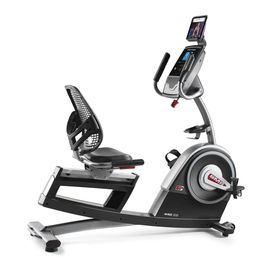
- Page 1 proform.com USER’S MANUAL Model No. PFEX15917.2 Serial No. Write the serial number in the space above for reference. Serial Number Decal ACTIVATE YOUR WARRANTY To register your product and activate your warranty today, go to my.proform.com. CUSTOMER CARE For service at any time, go to support.proform.com.
-
Page 2: Table Of Contents
TABLE OF CONTENTS WARNING DECAL PLACEMENT ............. . .2 IMPORTANT PRECAUTIONS . -
Page 3: Important Precautions
IMPORTANT PRECAUTIONS WARNING: To reduce the risk of serious injury, read all important precautions and instructions in this manual and all warnings on your exercise bike before using your exercise bike. ICON assumes no responsibility for personal injury or property damage sustained by or through the use of this product. - Page 4 STANDARD SERVICE PLANS...
-
Page 5: Before You Begin
The and toning the body. The 440 ES exercise bike pro- model number and the location of the serial number vides a selection of features designed to make your decal are shown on the front cover of this manual. -
Page 6: Part Identification Chart
PART IDENTIFICATION CHART Use the drawings below to identify the small parts needed for assembly. The number in parentheses below each drawing is the key number of the part, from the PART LIST near the end of this manual. The number following the key number is the quantity needed for assembly. -
Page 7: Assembly
ASSEMBLY • To hire an authorized service technician to • To identify small parts, see page 6. assemble this product, call 1-800-445-2480. In addition to the included tool(s), assembly • Assembly requires two persons. requires the following tools: one Phillips screwdriver •... - Page 8 3. With the help of a second person, place some of the packing materials (not shown) under the rear of the Frame (1). Attach the Rear Stabilizer (3) to the Frame (1) with two M10 x 120mm Screws (44); start both Screws, and then tighten them.
- Page 9 6. Attach the Accessory Tray (9) to the Upright (4) with an M6 x 50mm Screw (42). 7. Untie and discard the wire tie on the Main Wire (41). While a second person holds the Console Bracket (82) near the Upright (4), route the Main Wire (41) through the notch in the Upright, through the Upright Bracket (84), and through the hole in the center of the Console Bracket.
- Page 10 9. IMPORTANT: Turn the Adjustment Knob (83) until the Console Bracket (82) is in the most vertical position. While a second person holds the Console (5) near the Console Bracket (82), connect the wires on the Console to the Main Wire (41) and to the Left and Right Pulse Wires (7, 8).
- Page 11 11. Attach the Seat Handlebar (18) to the Seat Carriage (11) with four M8 x 38mm Screws (56); start all the Screws, and then tighten them. 12. Slide the Backrest Frame (14) onto the Seat Handlebar (18). Attach the Backrest Frame (14) with four M6 x 30mm Screws (51) and four M6 Washers (112);...
- Page 12 13. Attach the Seat (12) to the Seat Handlebar (18) with four M6 x 18mm Screws (67) and four M6 Washers (112) (only two of each are shown); start all the Screws, and then tighten them. 14. Identify the Right Pedal (29). Using an adjustable wrench, firmly tighten the Right Pedal (29) clockwise into the Right Crank Arm (99).
- Page 13 15. Attach the Tablet Holder (114) to the Console (5) with four Tablet Holder Screws (115); start all the Tablet Holder Screws, and then tighten them. 16. After the exercise bike is assembled, inspect it to make sure that it is assembled correctly, that it functions properly, and that all parts are properly tightened.
-
Page 14: How To Use The Exercise Bike
HOW TO USE THE EXERCISE BIKE HOW TO PLUG IN THE POWER ADAPTER HOW TO ADJUST THE PEDAL STRAPS IMPORTANT: If the exercise bike has been exposed To tighten a pedal to cold temperatures, allow it to warm to room strap, pull downward temperature before you plug in the power adapter. -
Page 15: How To Use The Console
HOW TO USE THE CONSOLE CONSOLE DIAGRAM FEATURES OF THE CONSOLE The console also offers a selection of onboard workouts. Each workout automatically changes the IMPORTANT: To activate your console and begin resistance of the pedals as it guides you through an using its exclusive features, see assembly step 17 effective workout. - Page 16 HOW TO USE THE MANUAL MODE Pulse (BPM)—This display will show your heart rate in beats per minute (bpm) when you use the 1. Begin pedaling or press any button on the handgrip heart rate monitor or the optional chest console to turn on the console.
- Page 17 Press the Home button to exit the workout and When your pulse is detected, your heart rate will return to the main menu. If necessary, press the appear in the display. For the most accurate Home button again. heart rate reading, hold the contacts for at least 15 seconds.
- Page 18 HOW TO USE AN ONBOARD WORKOUT in the display for a few seconds to alert you. The resistance of the pedals will then change. 1. Begin pedaling or press any button on the console to turn on the console. As you exercise, keep your pedaling speed near the target speed for the current segment.
- Page 19 HOW TO CONNECT YOUR TABLET TO THE 5. Disconnect your tablet from the console if CONSOLE desired. The console supports Bluetooth connections to tab- To disconnect your tablet from the console, first lets via the iFit–Smart Cardio Equipment app and to select the disconnect option in the iFit–Smart compatible heart rate monitors.
- Page 20 HOW TO USE THE SOUND SYSTEM HOW TO CHANGE CONSOLE SETTINGS To play music or audio books through the console 1. Select the settings mode. sound system while you exercise, plug a 3.5 mm male to 3.5 mm male audio cable (not included) into the To select the settings mode, press the gear button.
-
Page 21: Maintenance And Troubleshooting
MAINTENANCE AND TROUBLESHOOTING MAINTENANCE HOW TO ADJUST THE DRIVE BELT Regular maintenance is important for optimal If the pedals slip while you are pedaling, even while the performance and to reduce wear. Inspect and properly resistance is adjusted to the highest setting, the drive belt may need to be adjusted. -
Page 22: Fcc Information
HOW TO ADJUST THE REED SWITCH Locate the Reed Switch (35). Rotate the Left Crank Arm (100) until a Magnet (39) is aligned with the Reed If the console does not display correct feedback, the Switch. Next, loosen the Clamp Screw (A), slide the reed switch should be adjusted. -
Page 23: Exercise Guidelines
EXERCISE GUIDELINES Burning Fat—To burn fat effectively, you must exer- WARNING: cise at a low intensity level for a sustained period of Before beginning this time. During the first few minutes of exercise, your or any exercise program, consult your physi- body uses carbohydrate calories for energy. -
Page 24: Part List
PART LIST Model No. PFEX15917.2 R1119A Key No. Qty. Description Key No. Qty. Description Frame M6 x 30mm Screw Front Stabilizer M4 x 25mm Screw Rear Stabilizer M5 x 20mm Screw Upright M10 x 55mm Screw Console Resistance Motor Screw Left Handlebar M8 x 38mm Screw Left Pulse Sensor/Wire... - Page 25 Key No. Qty. Description Key No. Qty. Description M10 x 60mm Bolt M10 x 96mm Screw M8 Locknut M4 x 30mm Screw M6 x 15mm Screw M6 Washer Crank Snap Ring M8 Hex Nut Crank Tablet Holder Frame Cap Tablet Holder Screw Power Adapter –...
-
Page 26: Exploded Drawing
EXPLODED DRAWING A Model No. PFEX15917.2 R1119A... - Page 27 EXPLODED DRAWING B Model No. PFEX15917.2 R1119A...
-
Page 28: Ordering Replacement Parts
ORDERING REPLACEMENT PARTS To order replacement parts, please see the front cover of this manual. To help us assist you, be prepared to provide the following information when contacting us: • the model number and serial number of the product (see the front cover of this manual) •...
Need help?
Do you have a question about the 440 ES and is the answer not in the manual?
Questions and answers
The console is not lighting up when plugged in. Any idea what the cause is?
The console may not light up if the power adapter is not properly plugged in or if a replacement adapter is needed. It is important to use only a manufacturer-supplied regulated power adapter to avoid damage.
This answer is automatically generated
if a pulse wire is pinched, will that effect the adjustment on pedaling pressure from light to heavy? my unit will not move to light pedaling when turned down to the lowest #1 position.
No, a pinched pulse wire will not affect the pedaling pressure adjustment on a Pro-Form 440 ES when set to the lowest position. The pulse wire is related to heart rate monitoring, while pedaling resistance is controlled separately.
This answer is automatically generated
I cant find where to plug the electric on the front of the bike
The electric plug is located on the front of the Pro-Form 440 ES exercise bike.
This answer is automatically generated