Table of Contents
Advertisement
Quick Links
Advertisement
Table of Contents

Related Manuals for Parker PAC340


Summary of Contents for Parker PAC340
- Page 1 192-122023 PAC340: User Manual Parker Motion Controller PAC340 User Manual...
- Page 2 Copyright © Parker Hannifin Manufacturing GmbH Reproduction and duplication of this document and utilisation and communication of its content are prohibited without with our express permission. All rights reserved. Infringements will result in compensation for damages. Disclaimer The content of this document has been checked for conformity with the hardware and software de- scribed.
-
Page 3: Table Of Contents
2.2. Cyber Security ........................12 2.3. PRODUCT DESCRIPTION ....................13 Overview ..........................13 3.1. TECHNICAL DATA ......................14 PAC340 ..........................14 4.1. Scope of Delivery and Accessories ................. 15 4.2. Product features ........................ 16 4.3. ASSEMBLY .......................... 18 Installation .......................... 18 5.1. - Page 4 Switching on and off ......................27 7.1. Initial start-up of the network .................... 28 7.2. Operation ..........................31 7.3. 7.3.1. Status indicators ......................... 31 7.3.2. Real-time clock with battery back-up ................. 33 7.3.3. SD card ..........................33 7.3.4. Start/Stop reset button ....................... 34 Troubleshooting .........................
-
Page 5: General Information
1.1. Notes about this handbook This user handbook is a component of the product and applies to the following devices: PAC340-CWB11-3X-00-01 und PAC340-MWB11-3X-00-01 It contains information on the following topics: Areas of application ... -
Page 6: Symbols And Visual Depictions
1.2. Symbols and visual depictions The following symbols and visual depictions are used in this user handbook: Symbol Meaning … List entry … Individual instruction or list of instructions which can be carried out in any order. … List of instructions which must be carried out in the order given. -
Page 7: Hazard Categories And Indications
1.3. Hazard categories and indications The following indications are used for warning messages that must be observed to ensure your personal safety and avoid any damage to property. The indications have the following meanings: DANGER Serious injury or death Failure to observe the safety measures will result in death or serious injury. Take preventive measures. -
Page 8: Duty Of Care
1.5. Duty of care The user or processor (OEM) must ensure the following: The device must only be used for its intended purpose. The device must only be used in a perfect, fully functional condition. The user handbook must always be kept legible and fully available. ... -
Page 9: Intended Use
1.6. Intended use The device is a component of a modular automation system for industrial control applications in the medium to high performance range. The automation system is designed for use in overvoltage category I (IEC 364-4-443) for the control and regulation of machinery and industrial processes in low-voltage installations in ac- cordance with the following basic conditions. -
Page 10: Transport And Storage
1.7. Transport and storage The unit is sensitive to shocks, strong vibrations, humidity and extreme temperatures. Transport and storage Protect the unit from strong mechanical stresses during transport. Always transport the unit in its original packaging. Observe the environmental conditions applicable to storage. Protect the unit from precipitation and moisture. -
Page 11: Safety
Safety 2.1. Safety-related systems The use of PLC controls in safety-related systems requires specific measures. If a PLC control- ler is to be used in a safety-related system, the user must be given comprehensive advice by the PLC manufacturer in addition to any available standards or guidelines regarding safety in- stallations. -
Page 12: Cyber Security
2.3. Cyber Security Never place the controller on the Internet without further protection mechanisms, this em- bedded controller is not designed for this purpose. Change the default passwords given at delivery Always use a preceding external firewall, so that an external access is prevented Use the security mechanisms of VPN server portals (e.g. -
Page 13: Product Description
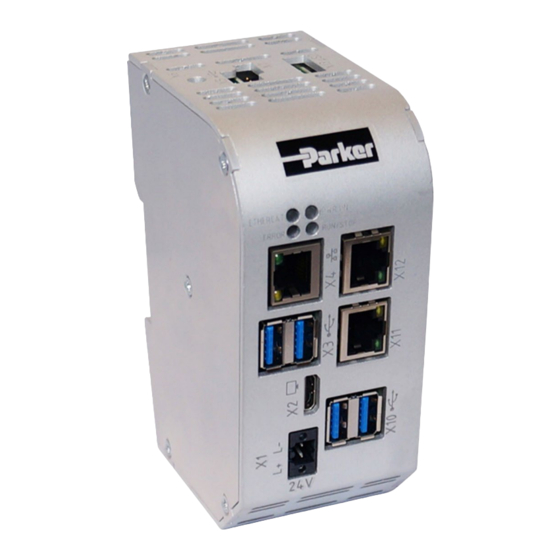
Product description 3.1. Overview Fig.: 1 Overview of PAC340 Pos. Description Pos. Description Power Supply Fan (option) Display Interface EtherCAT LVDS 2 x USB 3.0 2 x USB 3.0 Gbit LAN 100 Mbit LAN USB 2.0 / Boot 100 Mbit LAN... -
Page 14: Technical Data
Technical Data Protection rating IP20 4.1. PAC340 Description Order Number PAC340-CWB11-3X-00-01 und PAC340-MWB11-3X-00-01 Dimensions 53 x 122 x 89 (W x H x D[mm]) Assembly Din Rail NS 35/7,5 EN 50022 Certification CE (EN 61131-2) Development Tooling CODESYS V3 (IEC61131-3) -
Page 15: Scope Of Delivery And Accessories
Protection rating IP20 4.2. Scope of Delivery and Accessories Scope of delivery The scope of delivery PAC340 and the ordered accessories Accessories The following accessories is available on demand: Plug kit: plug kit with 1 x 2-pin plug for the power... -
Page 16: Product Features
4.3. Product features The PAC340 Motion Controller is a PLC with a wide range of data interfaces. The PAC340is a Raspberry Pi OS-based mini PC with expansion options for EtherCAT modules of the PACIO series. Mounting The PAC340 is designed for control cabinet installation on a DIN mounting rail in harsh indus- trial environments. - Page 17 Performance features at a glance 1.5 GHz CPU BCM2711 User programme and data memory (RAM): 2 GB onboard User programme memory (eMMC): 8 GB onboard 200 KB retain memory 1x Ethernet 10/100/1000 Base T interface 1x Ethernet 10/100 Base T, 2-port switch ...
-
Page 18: Assembly
Fig.: 2 Installing the PAC340 NOTICE There must be at least 100 mm clearance above and below the PAC340. This guarantees the necessary convection cooling for the PAC340. The mounting plate must be made of metal to ensure heat conduction. - Page 19 Press the module at the top against the mounting wall until it snaps into place. Turn the module forwards away from the mounting rail as shown in the illus- tration. Pull the module down off the mounting rail. Fig.: 3 Disconnecting the PAC340...
-
Page 20: Connection
Connection WARNING Uncontrolled and unpredictable operational behaviour! The failure of certain components in electronic control systems may result in uncontrolled and unpredictable operational behaviour. All types of failure and the associated fuse systems are to be taken into account at sys- ... -
Page 21: Connecting The Power Supply
6.1.1. Connecting the power supply CAUTION Live parts! Before starting any work on the device, switch off all power supplies, including those of connected peripherals. Connect the power supply to the plug according to the following table. Power supply plug Connector Function digital input 24 V DC (-20% / +25%) -
Page 22: Earthing
6.2. Earthing The PAC340 must be earthed. For this purpose, the metal housing must be connected to a functional earth. The functional earth is used to dissipate HF currents and is of great importance to the immunity of the module. HF interference is diverted from the electronic circuit board to the metal hous- ing. -
Page 23: Data Connections
6.3. Data connections 6.3.1. Block diagram Voltage Conversion Fig.: 5 Block diagram of PAC340... -
Page 24: 10/100/1000 Base-T Network Connection
6.3.2. 10/100/1000 Base-T network connection The onboard gigabit adapter with RJ-45 connection enables the network connection. The status LEDs "SPEED" and "LNK/RCV" provide information about a successful network con- nection according to IEEE 802.3 clause 40. Pin assignment Plug Function Function RJ45 Status-LEDs... - Page 25 NOTICE Damage to the USB thumb drive and malfunctions due to data loss! Removing a USB thumb drive while it is still in use and data is being transferred can render the USB thumb drive unusable. Open files which cannot be accessed due to removal of the USB thumb drive can block the device.
-
Page 26: Ethercat
Each EtherCAT I/O module generates an “E-bus load”. This refers to the current load required to supply the internal device electronics. The PAC340 provides a current of up to 2 A for this purpose. This means that one PAC340 can supply up to a maximum of 10 I/O modules. -
Page 27: Operation
Operation 7.1. Switching on and off NOTICE Damage or malfunction! Do not insert, connect, disconnect or touch any connections while the device is in operation. Before starting any work on the device, switch off all power supplies, including those to any connected peripherals (externally powered encoders, programming devices etc.). -
Page 28: Initial Start-Up Of The Network
7.2. Initial start-up of the network Starting-up via the web interface The device must be connected to the network with the correct settings before it can be used. Upon delivery, the IP-address and network mask are set to: IP address: 169.254.255.XX ... - Page 29 The web configuration page will be displayed. Fig.: 7 List of web interface settings Click on the “Network” link. The “Network Configuration” page will be displayed. Fig.: 8 Network Configuration page Check the network settings and make any changes in the text boxes, if required. Save the settings by clicking on “Save”.
- Page 30 In order to accept all of the modified settings, reboot the device: Briefly disconnect the device from the power supply. – or – Click on “Reboot” in the web interface and then confirm on the next page by clicking on “Re- boot Module”.
-
Page 31: Operation
7.3. Operation 7.3.1. Status indicators Fig.: PAC340 status indicators Power LED 4 operating status LEDs show the current status of the power supply, the module mode and any error messages. Logical status PWR (green) ON = power supply to the module electronics is correct. - Page 32 LEDs: RUN/STOP ERROR - LED indication 2 LEDs are available to indicate the system status (RUN/STOP in two colours: red/green/(yel- low); ERROR in red only). The LEDs indicate the following system statuses: System status LED RUN/STOP LED ERROR PPP configuration mode active Yellow USB package update active Flashing yellow...
-
Page 33: Real-Time Clock With Battery Back-Up
7.3.2. Real-time clock with battery back-up The PAC340 is equipped with a real-time clock. The buffer time is 30 days. Setting the date and time The time can be set either via the web configuration page or via the CODESYS V3 library. -
Page 34: Start/Stop Reset Button
7.3.4. Start/Stop reset button The Reset/Stop button is located on the front of the device below the status LEDs. To prevent unintentional operation, the Stop/Reset button can only be operated with a thin pointed object (pen, screwdriver). The function depends on the controller’s current operating status CODESYS Stop –... -
Page 35: Troubleshooting
7.4. Troubleshooting 7.4.1. No network connection Check the wiring/switch. Check whether an IP address has been assigned twice. Check the network settings on the PC: The subnet and subnet mask must match the set- tings in the controller. ... -
Page 36: Servicing / Maintenance
Servicing / Maintenance Repairs and corrective maintenance may only be carried out by the manufacturer or its author- ised customer service centres. WARNING Uncontrolled and unpredictable operational behaviour! Failures or malfunctions may result in uncontrolled and unpredictable operational behaviour. Do not insert, connect, undo or touch any connections while the device is in operation. -
Page 37: Disassembly
Press the module at the top against the mounting wall until it snaps into place. Turn the module forwards away from the mounting rail as shown in the illustration. Pull the module down off the mounting rail. Releaselatch Fig.: 9 Disassembling the PAC340... -
Page 38: Disposal
10. Disposal The device contains the following components which need to be disposed of separately: Metals Electronic components The respective national regulations for the disposal of electrical appliances in B2B business ap- ply. The following options are available for disposal of the device: Disposal by the manufacturer Unless otherwise agreed, devices can be returned for disposal. -
Page 39: Standards And Certificates
Industrial Control Equipment 17. Edition / 1999-01-28 UL 508 Technical documentation for the assessment of electrical and electronic products with re- spect to the restriction of hazardous substances EN 50581:2012 11.2. Declaration of Conformity The declaration of conformity is available on our website https://ph.parker.com/de/de/parker-motion-controller-pac-series... -
Page 40: Adresses
Repairs and corrective maintenance may only be carried out by the manufacturer or its author- ised customer service centres. 12.1. Division address Parker Hannifin Manufacturing Germany GmbH & Co. KG Electric Motion and Pneumatic Division Europe Robert-Bosch-Straße 22 77656 Offenburg (Germany) Tel.: 07841 / 509 –...
Need help?
Do you have a question about the PAC340 and is the answer not in the manual?
Questions and answers