Sign In
Upload
Manuals
Brands
YOKOGAWA Manuals
Analytical Instruments
ZR22S
YOKOGAWA ZR22S Manuals
Manuals and User Guides for YOKOGAWA ZR22S. We have
1
YOKOGAWA ZR22S manual available for free PDF download: User Manual
YOKOGAWA ZR22S User Manual (206 pages)
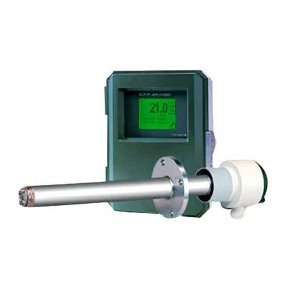
Separate type Explosion-proof Zirconia Oxygen Analyzer
Brand:
YOKOGAWA
| Category:
Analytical Instruments
| Size: 14.92 MB
Table of Contents
Table of Contents
12
1 Overview
20
Exaxt ZR > System Configuration
20
System 1
20
System 2
21
Exaxt ZR > System Components
22
System Components
22
Detectors and Accessories
22
2 Specifications
24
General Specifications
24
ZR22S Separate Type Explosion-Proof Detector
24
ZO21R Probe Protector
31
Separate Type Explosion-Proof Detector for High Temperature and Related Equipment
32
ZR22S (0.15 M) Separate Type Explosion-Proof Detector for High Temperature
32
ZO21P High Temperature Probe Adapter
33
ZR402G Separate Type Converter
35
Standard Specification
35
Functions
36
ZA8F Flow Setting Unit and ZR40H Automatic Calibration Unit
40
ZA8F Flow Setting Unit
40
ZR40H Automatic Calibration Unit
42
ZO21S Standard Gas Unit
44
Other Equipments
45
Ejector Assembly for High Temperature (E7046EC, E7046EN)
45
Stop Valve (L9852CB, G7016XH)
46
Check Valve (K9292DN, K9292DS)
47
Air Set
48
Cylinder Pressure Reducing Valve (G7013XF, G7014XF)
49
ZR22A Heater Assembly
50
3 Installation
53
Installation of General-Purpose Detector
54
Installation Location
54
ATEX Flameproof Type
54
FM Explosion-Proof Type
55
CSA Explosion-Proof Type
56
Iecex Flameproof Type
57
Probe Insertion Hole
59
Installation of the Detector
59
Installation of Probe Protector (ZO21R)
60
Installation of High Temperature Detector (Model ZR22S--015)
60
Installation Location
60
Usage of High Temperature Probe Adapter (Model ZO21P)
61
Probe Insertion Hole
62
Mounting of High Temperature Detector
63
Installation of ZR402G Converter
64
Installation Location
64
Mounting of the Converter
64
Installation of ZA8F Flow Setting Unit
66
Installation Location
66
Mounting of ZA8F Flow Setting Unit
66
Installation of ZR40H Automatic Calibration Unit
67
Installation Location
67
Mounting of ZR40H Automatic Calibration Unit
67
Insulation Resistance Test
69
4 Piping
71
Piping for a System Using Flow Setting Unit for Manual Calibration
72
Parts Required for Piping in a System Using Flow Setting Units for Manual Calibration
73
Piping for the Calibration Gas Inlet
74
Piping for the Reference Gas Inlet
74
Piping for the Reference Gas Outlet
74
Piping to the High Temperature Probe Adapter
74
Piping for a System to Perform Automatic Calibration
76
Parts Required for Piping in a System to Perform Automatic Calibration
77
Piping for the Calibration Gases
78
Piping for the Reference Gas
78
Piping to the High Temperature Probe Adapter
79
Piping for Blow Back
79
5 Wiring
81
General
81
Terminals for the External Wiring in the Converter
82
Wiring
83
Mounting of Cable Gland
84
Wiring for Detector Output
85
Cable Specifications
85
Connection to the Detector
86
Connection to the Converter
86
Wiring for Power to Detector Heater
87
Cable Specifications
87
Connection to Detector
87
Connection to Converter
88
Wiring for Analog Output
89
Cable Specifications
89
Wiring Procedure
89
Power and Grounding Wiring
89
Power Wiring
89
Grounding Wiring
90
Contact Output Wiring
90
Cable Specifications
91
Wiring Procedure
91
Wiring for ZR40H Automatic Calibration Unit
91
Cable Specifications
92
Wiring Procedure
92
Contact Input Wiring
92
6 Components and Their Functions
93
ZR22S Detector
93
General-Purpose Explosion-Proof Detector (Except for ZR22S--015)
93
High Temperature Detector (ZR22S--015)
94
ZR402G Converter
95
Touchpanel Switch Operations
96
Basic Panel and Switch
96
Display Configuration (for Oxygen Analyzer)
97
Display Functions
98
Entering Numeric and Text Data
98
ZA8F Flow Setting Unit, ZR40H Automatic Calibration Unit
100
7 Startup
101
Startup Procedure
101
Checking Piping and Wiring Connections
101
Checking Valve Setup
102
Supplying Power to the Converter
102
Confirmation of Converter Type Setting
103
Confirmation of Detector Type Setting
104
Selection of Sample Gas
104
Output Range Setting
104
Setting Display Item
105
Checking Current Loop
106
Checking Contact I/O
107
Checking Contact Outputs
107
Checking Calibration Contact Outputs
108
Checking Contact Inputs
108
Calibration
109
Calibration Setup
109
Manual Calibration
110
8 Detailed Data Setting
113
Current Output Setting
113
Setting Minimum Current (4 Ma) and Maximum Current (20 Ma)
113
Input Ranges
113
Setting Output Smoothing Coefficient
114
Selection of Output Mode
114
Default Values
114
Output Hold Setting
115
Definition of Equipment Status
115
Preference Order of Output Hold Value
116
Output Hold Procedure
116
Default Values
117
Oxygen Concentration Alarms Setting
118
Setting the Alarm Values
118
Alarm Output Actions
118
Alarm Setting Procedure
119
Default Values
120
Contact Output Setting
120
Contact Output
120
Setting Procedure
121
Default Values
123
Contact Input Setting
124
Contact Input Functions
124
Setting Procedure
125
Default Values
125
Other Settings
126
Setting the Date-And-Time
126
Setting Periods over Which Average Values Are Calculated and Periods over Which Maximum and Minimum Values Are Monitored
126
Setting Fuels
127
Setting Purging
132
Setting Passwords
133
9 Calibration
135
Calibration Briefs
135
Principle of Measurement
135
Calibration Gas
136
Compensation
137
Characteristic Data from a Sensor Measured During Calibration
138
Calibration Procedures
139
Calibration Setting
139
Default Values
142
Calibration
143
10 Other Functions
145
Detailed-Data Display
145
Cell Voltage
145
Thermocouple Voltage
146
Cold Junction Resistance (C.J. Voltage)
146
Cell's Internal Resistance
146
Software Revision
146
Span Gas and Zero Gas Correction Ratios
146
Cell Response Time
147
Robustness of a Cell
147
Cell Temperature
147
C. J. Temperature
148
Maximum Oxygen Concentration
148
Minimum Oxygen Concentration
148
Average Oxygen Concentration
148
Heater On-Time Ratio
148
Time
148
History of Calibration Time
148
Power Supply Voltage
148
Power Frequency
148
Trend Graph
149
Setting Display Items
149
Sampling Interval
149
Setting Upper and Lower Limit Values on Graph
150
Default Setting
150
Other Display-Related Functions
151
Auto-Return Time
151
Entering Tag Name
151
Language Selection
151
Blow Back
152
Mode of Blow Back
152
Operation of Blow Back
152
Setting Output Hold Time and Blow Back Time
153
Setting Interval, Start Date, and Start Time
153
Default Setting
154
Parameter Initialization
154
Reset
157
Handling of the ZO21S Standard Gas Unit
158
Standard Gas Unit Component Identification
158
Installing Gas Cylinders
159
Calibration Gas Flow
159
Methods of Operating Valves in the ZA8F Flow Setting Unit
162
Preparation before Calibration
162
Operating the Span Gas Flow Setting Valve
162
Operating the Zero Gas Flow Setting Valve
162
Operation after Calibration
163
11 Inspection and Maintenance
165
Inspection and Maintenance of the Detector
166
Cleaning the Calibration Gas Tube
166
Replacing the Sensor Assembly
166
Replacement of the Heater Unit (Assembly)
169
Replacement of Flame Arrestor Assembly
172
Replacement of O-Ring
172
Cleaning the High Temperature Probe Adapter
173
Stopping and Re-Starting Operation
173
Inspection and Maintenance of the Converter
174
Replacing Fuses
174
Cleaning
175
Adjust LCD Screen Contrast
175
Replacing Flowmeter in ZR40H Automatic Calibration Unit
176
12 Troubleshooting
177
Displays and Remedies When Errors Occur
177
Error Types
177
Remedies When an Error Occurs
178
Displays and Remedies When Alarms Are Generated
181
Alarm Types
181
Remedies When Alarms Are Generated
182
Countermeasures When Measured Value Shows Error
187
Measured Value Higher than True Value
187
Advertisement
Advertisement
Related Products
YOKOGAWA ZR202G
YOKOGAWA EXAxt ZR402G
YOKOGAWA ZS8
YOKOGAWA ZO21R
YOKOGAWA ZO21P
YOKOGAWA ZH21B
YOKOGAWA ZA8F
YOKOGAWA ZR40H
YOKOGAWA ZO21S
Yokogawa ZR22P
YOKOGAWA Categories
Measuring Instruments
Test Equipment
Transmitter
Controller
Media Converter
More YOKOGAWA Manuals
Login
Sign In
OR
Sign in with Facebook
Sign in with Google
Upload manual
Upload from disk
Upload from URL