Table of Contents
Advertisement
Quick Links
RF Energy Exposure Compliance
Your radio is designed and tested to comply with a number of national and international standards
and guidelines (listed below) regarding human exposure to radio frequency electromagnetic
energy.
This
radio
occupational/controlled RF exposure environment at operating duty factors of up to 50%
transmitting and is authorized by the FCC for occupational use only. In terms of measuring RF
energy for compliance with the FCC exposure guidelines, your radio radiates measurable RF
energy only while it is transmitting (during talking), not when it is receiving (listening) or in
standby mode.
Your radio complies with the following of RF energy exposure standards and guidelines
● United States Federal Communications Commission, Code of Federal Regulations; 47CFR
part 2 sub-part J
● American National Standards Institute (ANSI)/Institute of Electrical and Electronic
Engineers (IEEE) C95. 1-1992
● Institute of Electrical and Electronic Engineers (IEEE) C95. 1-1999 Edition
● International Commission on Non-Ionizing Radiation Protection (ICNIRP) 1998
Safety Information
The following safety precautions shall always be observed during operation, service and
repair of this equipment.
This equipment shall be serviced by qualified technicians only.
Do not modify the radio for any reason.
Use only HYT supplied or approved antenna.
Gain of antenna must not exceed 3.5dBi for VHF or 5.5dBi for UHF.
Mobile antenna Installation: Install the mobile antenna at least 100cm (34 inches)
away from your body, in accordance with the requirements of the antenna
manufacturer/supplier.
Transmit only when people inside and outside the vehicle are at least the minimum
distance away from a properly installed, externally mounted antenna.
Mobile antenna substitution: Don't substitute HYT supplied or approved antenna, or
excessive radio frequency radiation will result. Please contact your dealer or the
manufacturer for further instructions.
Please make sure there's no stress on the antenna joint during transportation or
installation.
complies
with
the
IEEE
and
ICNIRP
exposure
limits
for
Advertisement
Table of Contents

Related Manuals for HYT TM-628H


Summary of Contents for HYT TM-628H
- Page 1 Transmit only when people inside and outside the vehicle are at least the minimum distance away from a properly installed, externally mounted antenna. Mobile antenna substitution: Don’t substitute HYT supplied or approved antenna, or excessive radio frequency radiation will result. Please contact your dealer or the manufacturer for further instructions.
-
Page 2: Installation Guidelines
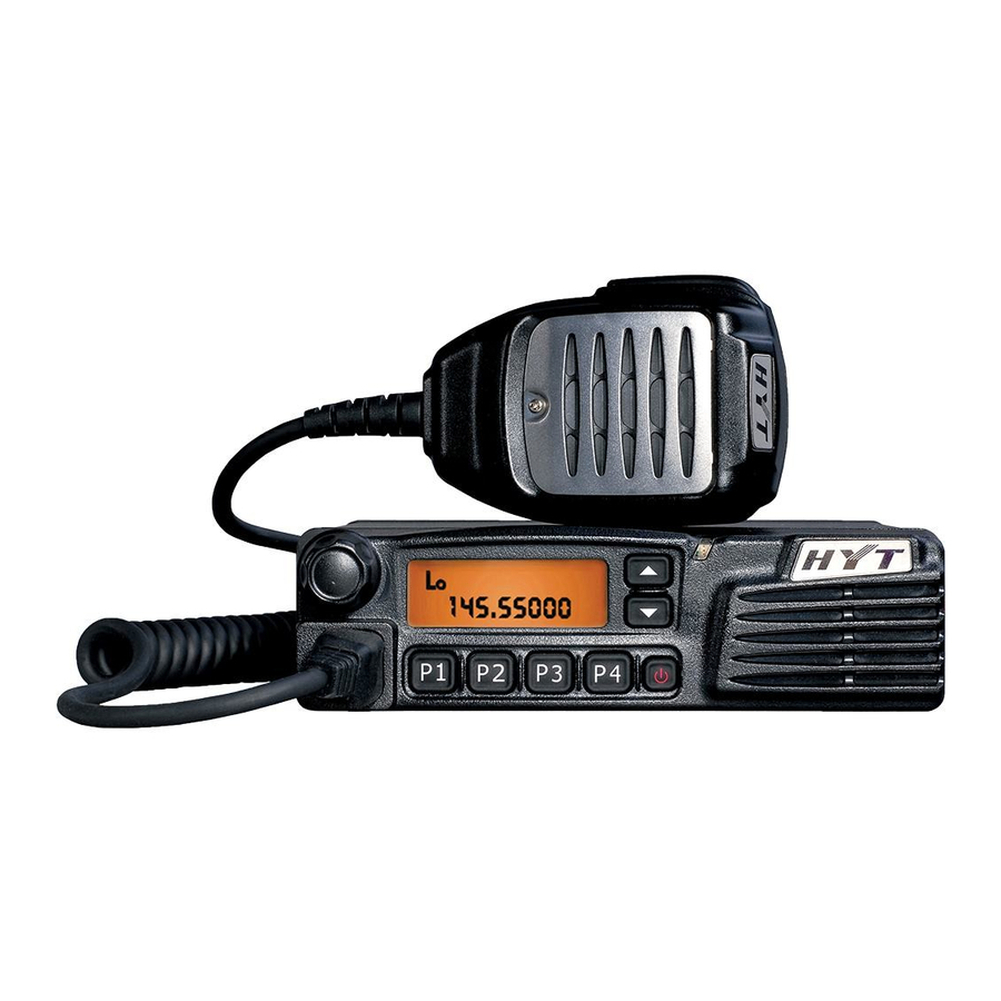
To avoid electromagnetic interference and/or compatibility conflicts, turn off your radio in any area where posted notices instruct you to do so. Hospital or health facilities may be using equipment that is sensitive to external RF energy. For vehicles with an air bag, do not place a radio in the area over an air bag or in the air bag deployment area. - Page 3 Preface Thank you for purchasing HYT TM-628H Mobile Radio. This easy-to-use radio will deliver you secure, instant and reliable communication at peak efficiency. To derive optimum performance from your radio, please read this manual and the supplied Safety Information Booklet carefully before use.
- Page 4 The HYT product described in this manual may include HYT computer programs stored in memory or other media. Laws in the PRC and/or other countries or areas preserve for HYT exclusive rights for HYT computer programs. The purchase of this product shall not be deemed to grant, either directly or by implication, any rights to the purchaser with respect to HYT computer programs.
-
Page 5: Table Of Contents
Contents Checking Items in the Package..................5 Radio Overview ....................... 6 Front Panel........................6 Rear Panel ........................7 Programmable Function Keys ..................7 Installation ........................9 Instructions........................9 Installation Tools ......................9 Installation Steps ......................9 Status Indicators ......................11 LCD Icons .........................11 LED Indicator ...................... - Page 6 HDC1200 ........................25 HDC2400 ....................... 26 Short Message ......................26 Troubleshooting ......................31 Care and Cleaning ......................31 Optional Accessories....................32...
-
Page 7: Checking Items In The Package
Checking Items in the Package Please unpack carefully and check that all items listed below are received. If any item is missing or damaged, please contact your dealer. Palm Microphone Microphone Hanger Microphone Hanger Screws Mounting Bracket Kit Fuse Vehicle Power Cord Owner’s Manual Safety Information Booklet Radio Unit... -
Page 8: Radio Overview
Radio Overview Front Panel Part Name Part Name ○ ○ Volume Control Knob LCD Display ○ ○ ▲/▼ LED Indicator Programmable Keys ○ ○ Speaker Power On/Off Key ○ ○ P1-P4 Programmable Keys Microphone Jack... -
Page 9: Rear Panel
Rear Panel Part Name Part Name ○ ○ Audio Connector External Speaker Jack ○ ○ Power Inlet Antenna Connector Programmable Function Keys For enhanced convenience, you may request your dealer to program the keys P1, P2, P3, P4, ▲ and ▼ as shortcuts to the functions listed below: Shortcut Keys Description... - Page 10 To add or delete the scan channel in non-scan status Add/Delete To delete the nuisance channel temporarily in scan status To reverse the TX and RX frequencies, and the Frequency Reverse CTCSS/CDCSS encoding and decoding frequencies To transmit with the RX frequency and CTCSS/CDCSS Talk Around frequency SEL SQL...
-
Page 11: Installation
Please connect the supplied antenna and power cord to the radio, before you install the radio in the bracket. Install the radio with HYT supplied mounting bracket, to avoid radio loose in case of accidents. The loose radio may cause bodily injury. - Page 12 Part Name Part Name ○ ○ Palm Microphone Adjust Knobs ○ ○ Radio unit Power Inlet ○ ○ Black Power Cord Red Power Cord ○ ○ Fuses Antenna Connector ○ ○ Flat Washers Spring Washers 4 × 16 mm ○ ○...
-
Page 13: Status Indicators
Status Indicators LCD Icons The LCD of your radio displays the radio status. The following are the icons that appear on the radio’s display. LCD panel Status Icons Indicator Description Displays CH number/name, zone number/name, DTMF number, frequency, menu and options, etc. Indicates low power output. -
Page 14: Led Indicator
Appears when the Compandor feature is enabled. Appears when the current channel is already in use. P• Indicates the current channel is the priority channel. indicates priority channel 1, indicates priority channel 2, indicates priority channels 1 and LED Indicator The LED indicator will help you easily identify current radio status. -
Page 15: Basic Operations
Basic Operations Turning the Radio On/Off Press the Power On/Off key to turn on the radio. Press and hold down the Power On/Off key for about 1 second to turn off the radio. Adjusting the Volume Turn the Volume Control knob clockwise to increase the volume, or counter-clockwise to decrease the volume. -
Page 16: Transmitting A Call
Transmitting a Call When transmitting a call, please follow steps below: 1. Hold down the PTT key on the microphone. 2. Speak into the microphone. The red LED lights during calling. 3. Release the PTT key to return to the RX mode. 4. -
Page 17: Functions And Operations
Functions and Operations Monitor If the Monitor function is set by your dealer, press the programmed Monitor key in Rx mode to get aware of the activities on the current channel. The Monitor key is programmable with one of the following four operating modes by your dealer: 1. - Page 18 The scanning pauses or ceases upon the following: 1. Press the programmed Channel Scan key and cease the scanning, so that the radio may exit the scan mode. 2. Activate the Monitor function. 3. The radio receives the carriers which satisfy radio unmute condition ▇...
-
Page 19: Busy Channel Lockout (Bcl)
Channels in the scan list are allowed to be temporarily deleted When the scan pauses on an unwanted channel, such as a nuisance channel, press the programmed Add/Del Scan key to temporarily delete the channel from the scan list, and then the scan reinitiates immediately. - Page 20 ▇ Keypad Auto PTT If this feature is enabled by your dealer, press any numeric key to transmit DTMF signal without PTT key press. Stor e & Send ▇ When this feature is enabled, enter a pre-stored DTMF number (up to 16 digits) in Rx mode, and then press the PTT key on the microphone to initiate a call;...
-
Page 21: Code Squelch
1. Press the * key on the microphone keypad, and then the LCD displays A --. 2. Enter the memory number (01~32), and the LCD displays the stored number or its alias. 3. Press any key other than the PTT, and the LCD resumes its initial display. ▇... -
Page 22: Off Hook Decode
transpond if a zone call is received. ▇ Transmit 1. Hold down the PTT key 2. During encoding, the LED lights red. Please refer to the TTS key for 2-Tone encoding. 3. Upon release the PTT key, the signaling squelch is disabled; the icon flashes on the LCD, and LED flashes orange. -
Page 23: Emergency Call
▇ TOT Reset Time The TOT Reset timer is activated upon release of the PTT key. And the TOT timer will not be reset until the TOT Reset timer expires. Press the PTT key before the TOT Reset timer expires, and the TOT timer continues to countdown. -
Page 24: Selectable Squelch Level (Sql)
Enabled Disabled Selectable Squelch Level (SQL) 1. Press the SQL key (programmable function key), and the LCD displays the current squelch level as shown below: 2. Select the desired squelch level via the programmable function key ▲/▼. 3. Press any key of P1-P4 to save the selected squelch level. The LCD resumes its initial display. Note: High squelch level may cause the radio to ignore weak signals;... -
Page 25: Home Channel
3. Speak into the microphone after PTT is held down, the PA process initiates, and the LCD displays PA ON. When the PA process initiates in PA mode, you can adjust the volume via the volume control knob. 4. Release the PTT key to end the PA process, then the radio returns to the PA mode, and the LCD displays PA. -
Page 26: Lone Worker
Lone Worker When this function is enabled, an alert tone will sound if the preset time elapses. Then the user must press any key to indicate that he/she is safe, otherwise the emergency procedure will be activated. This feature provides an added security and safety feature for individuals who work remotely from their team. Operations are detailed as follows: Upon press of the Lone Worker function key, the LCD will display LONE ON, and the Lone Worker function will be activated. -
Page 27: Voice Compandor
1. Channel alias. 2. Zone number followed by channel number, such as “1 –CH 1”. 3. Zone alias. 4. Channel frequency. 5. Channel number followed by zone number, such as “CH 1– 1”. Voice Compandor Press the programmed Voice Compandor key to toggle the voice Compandor feature ON or OFF. When the feature is enabled, the LCD displays the icon. -
Page 28: Hdc2400 Tm
message. The receiver radio will reply with a message automatically upon receipt of the Safety Check message. HDC2400 HDC call list select (HDC List) Press the HDC Call Select key (Programmable function key) and the preset number or alias in the HDC list will be displayed on the LCD. - Page 29 The general operations of short message are shown in the following flowchart: Menu operations are as follows: 1) Press P4 to confirm; 2) Press P1 to back to the previous menu; 3) Press ▲/▼ to perform menu selections. Read A Short Message If the alert tone or short message icon is set, the radio will give the preset alert when a short message is received.
- Page 30 Select the NEW MSG option. Input the message you want to send. (See Note 1.) Select SENDONLY, SENDSAVE and SAVEONLY. If SENDONLY or SENDSAVE is selected, go with the following steps: Choose to send to individual / group etc. Use ▲/▼ to input the receiver’s ID (Individual / Group, etc). (See Note 1.) The user may also press P4 to access the ID menu without inputting the ID.
- Page 31 The user may also press P4 to access the ID menu without inputting ID. Press P4 or PTT to send the message. Read and Delete A Short Message When VIEW MSG is selected from the menu, two options are available: Read the received short message, the LCD will display RECEIVED.
- Page 32 the Inbox. Delete All the Received Messages When DEL ALL is selected from the menu, all the received messages except protected ones will be deleted upon press of P4. Press the Message key (programmable function key) to access the short message menu, and then select the DEL ALL option.
-
Page 33: Troubleshooting
Troubleshooting Phenomena Analysis Solution The equipment can not The power cord may be Connect the power cord correctly. be powered on. unconnected. You can not log on to The antenna is not connected. Connect the antenna properly. the system. The crystal connector is inserted Insert the crystal connector You can not use the improperly or not inserted. -
Page 34: Optional Accessories
External Speaker SM09S2 CP06 Programming Cable (COM Port) Cloning Cable Desktop Microphone SM10R2 PC21 Note: Use the accessories specified by HYT only. If not, HYT shall not be liable for any losses or damages arising out of use of unauthorized accessories.
Need help?
Do you have a question about the TM-628H and is the answer not in the manual?
Questions and answers