Table of Contents
Advertisement
Advertisement
Table of Contents

Related Manuals for HYT TM-628H


Summary of Contents for HYT TM-628H
- Page 1 MOBILE RADIO TM -628H L06774 X05031 8130062800000...
-
Page 2: Table Of Contents
TM-628H Service Manual Contents Introduction………………………………………………………………………………………..2 Safety Information………………………………………………………………………………..2 Radio Overview…………………………………………….……………………………………..4 Software Specification…………………………………….…………………………………..7 Circuit Description…………………………………….………………………………………...13 Semiconductor Data…………………………………….………………………………………18 Component Description…………………………………….………………………………….23 Parts List 1…………………………………….………………………………………………….24 Tuning Description…………………………………….………………………………………..62 Terminal Function…………………………………….…………………………………………76 Troubleshooting Flow Chart…………………………………….…………………………….79 Disassembly and Re-assembly for Repair…………………….……………………………83 Exploded View…………………….……………………………….…………………………….86 Parts List 2…………………….…………………………...……….…………………………….87 Packing…………………….…………………………………………….…………………….….89 PCB View………………….……………………………….……………………………….……..90 Block Diagram…………….……………………………….……………………………….…..96... - Page 3 TM-628H Service Manual Introduction Manual Scope This manual is intended for use by experienced technicians familiar with similar types of communication equipment. It contains all service information required for the equipment and is current as of the publication date. Safety Information The following safety precautions shall always be observed during operation, service and repair of this equipment.
-
Page 4: Installation Guidelines
TM-628H Service Manual ▇ Operation Guidelines For vehicles equipped with electronic anti-skid braking systems, electronic ignition systems or electronic fuel injection systems, interferences may occur during radio transmission. If the foregoing electronic equipments are installed on your vehicle, please contact your dealer for further assistance to make sure that radio transmission will not interfere with these equipments. -
Page 5: Radio Overview
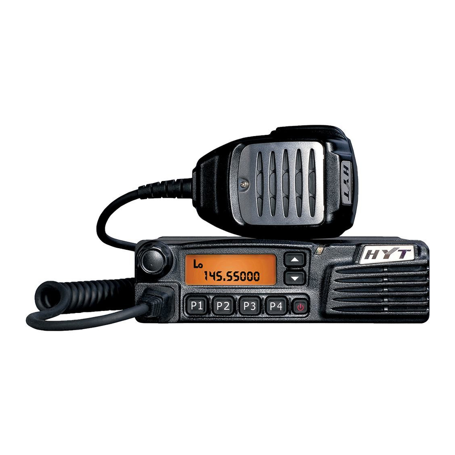
TM-628H Service Manual Radio Overview Front Panel View ① Volume Control Knob ② LCD ③ Programmable Functions Keys ([▲] / [▼]) ④ LED Indicator ⑤ Speaker ⑥ Power Switch ⑦ Programmable Functions Keys ([P1]/[P2]/[P3]/[P4]) ⑧ Mic Jack... -
Page 6: Led Indicator
TM-628H Service Manual Rear Panel View ① 15-Pin Connector (for external expansion) ② External Speaker Jack Used to connect the external speaker (for the 3.5mm plug only). Note: Please refer to “Test Cable for Speaker Output” in “Tuning Description” for details. -
Page 7: Lcd Display
TM-628H Service Manual ▇ LCD Display Indicator Description Displays CH number/name, zone number/name, DTMF number, frequency, menu and options, etc. Indicates low power output. Press the Monitor key: 1. The icon is displayed when CTCSS/CDCSS and 2-Tone decoding is off. -
Page 8: Software Specification
TM-628H Service Manual Software Specification Frame of Radio Modes Conventional Mode User Mode Tuning Mode Model Set Mode Wired Clone Mode Clone Mode Wireless Clone Mode PC Mode Keypad Entry for Mode Startup Mode Display Operation Remarks Welcome Screen and then CH... - Page 9 TM-628H Service Manual Panel Tuning Mode You can perform tuning in the following steps: 1) Power on the radio while holding down P1 to enter the tuning mode. 2) Use ▲/▼ to select the tuning item, and press P4 to enter.
- Page 10 TM-628H Service Manual Press P4 on the source radio to start cloning. LED on the source radio glows red, and it begins to transmit data to the target radio. During the cloning process, LCD of the target radio displays “PROGRAM” and its LED glows green. Upon completion of cloning, LCD of the source radio displays “END”.
- Page 11 TM-628H Service Manual Firmware Version Display Mode Power on the radio while holding down P4. The LCD displays the firmware version accordingly. Release P4 to enter User Mode automatically. PC Mode Connect the mobile radio to a PC using a programming cable. Data can be transmitted to the mobile radio and saved in the EEPROM.
- Page 12 TM-628H Service Manual Key Assignment Your dealer may assign one of the following functions to the programmable key (P1/ P2/ P3/ P4/ ▲/ ▼). See the table below for reference. Key Assignment Function Settings Display Remarks [P1]-[P4] No function &...
- Page 13 TM-628H Service Manual Short Message Message Menu Short Message Remaining Rental Time Inquires about the remaining rental Inquiry Remaining Time time. AUX A AUX A AUX A AUX B AUX B AUX B HOOK/ MONI This option should be selected when palm Hook Check microphone is used.
-
Page 14: Circuit Description
TM-628H Service Manual Circuit Description 1. Frequency Configuration The receiver utilizes double conversion superheterodyne. The first IF is 49.95MHz and the second IF is 450KHz. The first local oscillator signal is supplied by the PLL circuit, while the second local oscillator signal (49.5MHz) is generated from X401 directly. -
Page 15: Transmitter Circuit
TM-628H Service Manual pair of ceramic filters (N: CF202; W: CF203) where unwanted signals are removed. Finally the signal goes to the frequency discriminating circuit of IC102 to output audio signal from Pin 9. 2.4 Audio Amplifier Circuit The audio signal from IC102 is amplified and filtered at IC402, and then amplified again at IC401 (the received signaling is separated and sent to CPU for decoding). - Page 16 TM-628H Service Manual The DI modulation circuit is composed of IC407 and peripheral circuits (see the figure above). The signal goes to the DI modulation circuit via the TXAF_DI port, and then goes to the VCO unit. The signal amplitude can be adjusted manually via VR802, allowing accurate modulation of DI without any distortion.
- Page 17 TM-628H Service Manual Fig. 3 PLL Circuit 5. Control Circuit The circuit comprises CPU circuit, reset circuit and power control circuit. 5.1 CPU IC120 (CPU) operates at 9.8304MHz, and controls EEPROM (IC501), RX circuit, TX circuit, control circuit and display circuit, as well as data transmission with peripheral equipment.
-
Page 18: Display Circuit
TM-628H Service Manual 5.3 Power Control Circuit Power supply of the radio is derived from +B. D515 and D516 are diodes for over-voltage protection. The power can be switched on or off via software (see the figure below): Fig. 5 Power Supply Circuit Vout supplies power for IC601, IC602 and IC803, which generate 8V, 5V and 3.3V voltage respectively... -
Page 19: Semiconductor Data
TM-628H Service Manual Semiconductor Data 1. Positive voltage regulator: TA7805F (Power Unit IC602), TA7808S (Power Unit IC601) 2. EEPROM: CAT24C256WI 256K CATALYST (CPU Unit IC501) Pin Function Pin No. Name Function A0~A2 Address input Ground Serial data input/output Serial clock input... - Page 20 TM-628H Service Manual Audio Power Amplifier: TDA7297D (AFPwr Unit IC511) Pin No. Name Function PW GND Power ground 1 OUT1+ Output 1+ OUT1- Output 1- Supply voltage Input 1 Operating Switch STAND-BY Operating Switch PW GND Power ground 2 PW GND...
- Page 21 TM-628H Service Manual 49, 50 S19, S20 LCD output 51~64 S21~S34 LCD output Amplifier: TA75W558FU (AFPr Unit IC404), TC75W51FU (AFPr Unit IC402, AFPr Unit IC405, AFPr Unit IC403), TA75S01F (RF Unit IC1037), TA75W01FU (RF Unit IC404). IF detector: BA4116FV (RF Unit IC102).
- Page 22 TM-628H Service Manual P70/TXD2 TXD2 Not used P67/TXD1 TXD1 Serial data output L: PTT On P66/RXD1 RXD1 Palm MIC HOOK input/serial data input L: On AUX4 AUX 4 AUX5 AUX 5 TXD2 Acc comm0 (serial data output) RXD2 Acc comm0 (serial data input)
- Page 23 TM-628H Service Manual TX/RX VCO switch L: RX EEPDAT EEPROM data input/output EEPCLK EEPROM clock output PLLUL PLL unlock detect L: Unlock PLLSTB PLL strobe output L: Lock AFMUTE RX audio mute H: Mute /IGN Ignition sensor input H: Off L: On...
-
Page 24: Component Description
TM-628H Service Manual Component Description TX-RX Unit Ref. No. Part Name Type Description IC101 Power module Power module IC501 AT2408N12.5S EROM IC401 AK2346 Audio processor IC404 TA75W558FU Dual operational amplifier IC403 TC75W51FU Dual operational amplifier IC803 XC62FP3302P Positive voltage regulator... -
Page 25: Parts List 1
TM-628H Service Manual Parts List 1 VHF Parts List 1 (Main Board Unit) Description Material No. Qty. Ref. No. Print No. 1 3001050000000 Chip resistor 0Ω J 1/16W 0402 (RoHS) C177 2 3001050000000 Chip resistor 0Ω J 1/16W 0402 (RoHS) C404 3 3001050000000 Chip resistor 0Ω... - Page 26 TM-628H Service Manual 48 3001051010000 Chip resistor 100Ω J 1/16W 0402 (RoHS) R174 49 3001051010000 Chip resistor 100Ω J 1/16W 0402 (RoHS) R197 50 3001051010000 Chip resistor 100Ω J 1/16W 0402 (RoHS) R501 51 3001051010000 Chip resistor 100Ω J 1/16W 0402 (RoHS) R649 52 3001051020010 Chip resistor 1KΩ...
- Page 27 TM-628H Service Manual 101 3001051040010 Chip resistor 100KΩ J 1/16W 0402 (RoHS) R119 102 3001051040010 Chip resistor 100KΩ J 1/16W 0402 (RoHS) R120 103 3001051040010 Chip resistor 100KΩ J 1/16W 0402 (RoHS) R125 104 3001051040010 Chip resistor 100KΩ J 1/16W 0402 (RoHS) R128 105 3001051040010 Chip resistor 100KΩ...
- Page 28 TM-628H Service Manual 154 3001051840000 Chip resistor 180KΩ J 1/16W 0402 (RoHS) R832 155 3001052200000 Chip resistor 22Ω J 1/16W 0402 (RoHS) R803 156 3001052200000 Chip resistor 22Ω J 1/16W 0402 (RoHS) R808 157 3001052210000 Chip resistor 220Ω J 1/16W 0402 (RoHS) R117 158 3001052210000 Chip resistor 220Ω...
- Page 29 TM-628H Service Manual 207 3001054720000 Chip resistor 4.7KΩ J 1/16W 0402 (RoHS) R171 208 3001054720000 Chip resistor 4.7KΩ J 1/16W 0402 (RoHS) R401 209 3001054720000 Chip resistor 4.7KΩ J 1/16W 0402 (RoHS) R447 210 3001054720000 Chip resistor 4.7KΩ J 1/16W 0402 (RoHS) R469 211 3001054720000 Chip resistor 4.7KΩ...
- Page 30 TM-628H Service Manual 260 3001051820010 Chip resistor 1.8KΩ F 1/16W 0402 (RoHS) R129 261 3001051820010 Chip resistor 1.8KΩ F 1/16W 0402 (RoHS) R150 262 3001060000000 Chip resistor 0Ω J 1/10W 0603 (RoHS) D502 263 3001060000000 Chip resistor 0Ω J 1/10W 0603 (RoHS) R140 264 3001060000000 Chip resistor 0Ω...
- Page 31 TM-628H Service Manual 313 3001064730000 Chip resistor 47KΩ J 1/10W 0603 (RoHS) R551 314 3001064730000 Chip resistor 47KΩ J 1/10W 0603 (RoHS) R561 315 3001065620010 Chip resistor 5.6KΩ J 1/10W 0603 (RoHS) R810 316 3001061520000 Chip resistor 1.5KΩ J 1/10W 0603 (RoHS) R817 317 3001061520000 Chip resistor 1.5KΩ...
- Page 32 TM-628H Service Manual 366 3101051020010 Chip capacitor 1000PF K 50V 0402 (RoHS) C129 367 3101051020010 Chip capacitor 1000PF K 50V 0402 (RoHS) C134 368 3101051020010 Chip capacitor 1000PF K 50V 0402 (RoHS) C140 369 3101051020010 Chip capacitor 1000PF K 50V 0402 (RoHS)
- Page 33 TM-628H Service Manual 419 3101051030020 Chip capacitor 0.01UF K 25V 0402 (RoHS) C243 420 3101051030020 Chip capacitor 0.01UF K 25V 0402 (RoHS) C401 421 3101051030020 Chip capacitor 0.01UF K 25V 0402 (RoHS) C456 422 3101051030020 Chip capacitor 0.01UF K 25V 0402 (RoHS) C461 423 3101051030020 Chip capacitor 0.01UF K 25V 0402 (RoHS)
- Page 34 TM-628H Service Manual 472 3101051050000 Chip capacitor 3PT 1UF K 6.3V 0402 (RoHS) C609 473 3101051050000 Chip capacitor 3PT 1UF K 6.3V 0402 (RoHS) C927 474 3101051050000 Chip capacitor 3PT 1UF K 6.3V 0402 (RoHS) C928 475 3101053000010 Chip capacitor 30PF J 50V 0402 (RoHS) C162 476 3101051230000 Chip capacitor 0.012UF K 25V 0402 (RoHS)
- Page 35 TM-628H Service Manual 525 3101054710010 Chip capacitor 470PF K 50V 0402 (RoHS) C558 526 3101054710010 Chip capacitor 470PF K 50V 0402 (RoHS) C559 527 3101054710010 Chip capacitor 470PF K 50V 0402 (RoHS) C560 528 3101054710010 Chip capacitor 470PF K 50V 0402 (RoHS)
- Page 36 TM-628H Service Manual 578 3101061020000 Chip capacitor 1000PF K 50V 0603 (RoHS) C217 579 3101061020000 Chip capacitor 1000PF K 50V 0603 (RoHS) C220 580 3101061020000 Chip capacitor 1000PF K 50V 0603 (RoHS) C223 581 3101061020000 Chip capacitor 1000PF K 50V 0603 (RoHS)
- Page 37 TM-628H Service Manual 631 3104084750040 Tantalum capacitor 1206 4.7uF K 16V (RoHS) C524 632 3104084750040 Tantalum capacitor 1206 4.7uF K 16V (RoHS) C601 633 3104074750070 Tantalum capacitor 4.7UF M 10V (RoHS) C142 634 3104074750070 Tantalum capacitor 4.7UF M 10V (RoHS) C246 635 3104074750070 Tantalum capacitor 4.7UF M 10V (RoHS)
- Page 38 TM-628H Service Manual 684 3210306101000 Multi-layer chip inductor 100nH J 300mA (RoHS) L119 685 3210306390000 Multi-layer chip inductor 39nH J 300mA (RoHS) L115 686 3210306390000 Multi-layer chip inductor 39nH J 300mA (RoHS) L120 687 3210306390000 Multi-layer chip inductor 39nH J 300mA (RoHS)
- Page 39 TM-628H Service Manual 737 3221506601000 Bead 600Ω 100MHz ±25% 500mA 0603 (RoHS) L530 738 3221506601000 Bead 600Ω 100MHz ±25% 500mA 0603 (RoHS) L531 739 3221506601000 Bead 600Ω 100MHz ±25% 500mA 0603 (RoHS) L532 740 3221506601000 Bead 600Ω 100MHz ±25% 500mA 0603 (RoHS) L533 741 3221506601000 Bead 600Ω...
- Page 40 TM-628H Service Manual 790 3401002000290 NPN Transistor 50V 150mA 200~400 (RoHS) Q404 791 3401002000290 NPN Transistor 50V 150mA 200~400 (RoHS) Q704 792 3401002000290 NPN Transistor 50V 150mA 200~400 (RoHS) Q705 793 3401002000290 NPN Transistor 50V 150mA 200~400 (RoHS) Q801 794 3401002000990 NPN Transistor 10V 30mA 120~240 (RoHS)
- Page 41 TM-628H Service Manual 843 3608015005600 Power management IC 3V 250mA (RoHS) IC803 844 3609007001590 IF processor 1.1GHz (RoHS) IC801 845 3612022000000 Memory 256K 1.8~5.5V (RoHS) IC501 846 3613034001060 Baseband processor 1.5~5.9V (RoHS) IC401 847 3701016850020 TCXO 16.8MHz 3.0V ±2.0ppm (RoHS) IC802 848 3701098340010 Crystal ±30ppm 20pF (RoHS)
- Page 42 900 3210106560000 Wound chip inductor 56nH G 360mA (RoHS) L109 901 3001066810010 Chip resistor 680Ω J 1/10W 0603 (RoHS) R181 902 1616100001430 Embedded software of HYT mobile radio (RoHS) 903 3001061540000 Chip resistor 150KΩ J 1/10W 0603 (RoHS) R717 904 3001052740000 Chip resistor 270KΩ J 1/16W 0402 (RoHS) R446 905 3001052790000 Chip resistor 2.7Ω...
- Page 43 TM-628H Service Manual UHF Parts List 1 (Main Board Unit) Material No. Description Qty. Ref. No. Print No. 1 3001050000000 Chip resistor 0Ω J 1/16W 0402 (RoHS) C404 2 3001050000000 Chip resistor 0Ω J 1/16W 0402 (RoHS) R106 3 3001050000000 Chip resistor 0Ω J 1/16W 0402 (RoHS) R110 4 3001050000000 Chip resistor 0Ω...
- Page 44 TM-628H Service Manual 50 3001050000000 Chip resistor 0Ω J 1/16W 0402 (RoHS) R912 51 3001050000000 Chip resistor 0Ω J 1/16W 0402 (RoHS) R913 52 3001050000000 Chip resistor 0Ω J 1/16W 0402 (RoHS) R919 53 3001050000000 Chip resistor 0Ω J 1/16W 0402 (RoHS) R921 54 3001050000000 Chip resistor 0Ω...
- Page 45 TM-628H Service Manual 103 3001051040010 Chip resistor 100KΩ J 1/16W 0402 (RoHS) R104 104 3001051040010 Chip resistor 100KΩ J 1/16W 0402 (RoHS) R107 105 3001051040010 Chip resistor 100KΩ J 1/16W 0402 (RoHS) R115 106 3001051040010 Chip resistor 100KΩ J 1/16W 0402 (RoHS) R116 107 3001051040010 Chip resistor 100KΩ...
- Page 46 TM-628H Service Manual 156 3001052210000 Chip resistor 220Ω J 1/16W 0402 (RoHS) R117 157 3001052210000 Chip resistor 220Ω J 1/16W 0402 (RoHS) R172 158 3001052210000 Chip resistor 220Ω J 1/16W 0402 (RoHS) R204 159 3001052220000 Chip resistor 2.2KΩ J 1/16W 0402 (RoHS) R604 160 3001052230010 Chip resistor 22KΩ...
- Page 47 TM-628H Service Manual 209 3001054730000 Chip resistor 47KΩ J 1/16W 0402 (RoHS) R179 210 3001054730000 Chip resistor 47KΩ J 1/16W 0402 (RoHS) R199 211 3001054730000 Chip resistor 47KΩ J 1/16W 0402 (RoHS) R202 212 3001054730000 Chip resistor 47KΩ J 1/16W 0402 (RoHS) R405 213 3001054730000 Chip resistor 47KΩ...
- Page 48 TM-628H Service Manual 262 3001061020010 Chip resistor 1KΩ J 1/10W 0603 (RoHS) R109 263 3001061020010 Chip resistor 1KΩ J 1/10W 0603 (RoHS) R557 264 3001061020010 Chip resistor 1KΩ J 1/10W 0603 (RoHS) R560 265 3001061020010 Chip resistor 1KΩ J 1/10W 0603 (RoHS) R568 266 3001061020010 Chip resistor 1KΩ...
- Page 49 TM-628H Service Manual 315 3005051020000 Integrated resistor 1K J 1/16W 2*0402 (RoHS) CP514 316 3005051020000 Integrated resistor 1K J 1/16W 2*0402 (RoHS) CP515 317 3005051020000 Integrated resistor 1K J 1/16W 2*0402 (RoHS) CP516 318 3005051020000 Integrated resistor 1K J 1/16W 2*0402 (RoHS)
- Page 50 TM-628H Service Manual 368 3101051040010 Chip capacitor 0.1UF Z 25V 0402 (RoHS) C154 369 3101051040010 Chip capacitor 0.1UF Z 25V 0402 (RoHS) C165 370 3101051040010 Chip capacitor 0.1UF Z 25V 0402 (RoHS) C167 371 3101051040010 Chip capacitor 0.1UF Z 25V 0402 (RoHS) C168 372 3101051040010 Chip capacitor 0.1UF Z 25V 0402 (RoHS)
- Page 51 TM-628H Service Manual 421 3101052220010 Chip capacitor 2200pF K 50V 0402 (RoHS) C455 422 3101052700000 Chip capacitor 27PF J 50V 0402 (RoHS) C124 423 3101052700000 Chip capacitor 27PF J 50V 0402 (RoHS) C246 424 3101052700000 Chip capacitor 27PF J 50V 0402 (RoHS)
- Page 52 TM-628H Service Manual 474 3101054710010 Chip capacitor 470PF K 50V 0402 (RoHS) C822 475 3101054720000 Chip capacitor 4700PF K 50V 0402 (RoHS) C402 476 3101054740020 Chip capacitor 0.47uF K 10V 0402 (RoHS) C420 477 3101054740020 Chip capacitor 0.47uF K 10V 0402 (RoHS) C422 478 3101054740020 Chip capacitor 0.47uF K 10V 0402 (RoHS)
- Page 53 TM-628H Service Manual 527 3101061040010 Chip capacitor 0.1UF K 16V 0603 (RoHS) C521 528 3101061040010 Chip capacitor 0.1UF K 16V 0603 (RoHS) C528 529 3101061040010 Chip capacitor 0.1UF K 16V 0603 (RoHS) C534 530 3101061040010 Chip capacitor 0.1UF K 16V 0603 (RoHS)
- Page 54 TM-628H Service Manual 580 3104074750070 Tantalum capacitor 4.7UF M 10V (RoHS) C448 581 3104074750070 Tantalum capacitor 4.7UF M 10V (RoHS) C457 582 3104074750070 Tantalum capacitor 4.7UF M 10V (RoHS) C464 583 3104074750070 Tantalum capacitor 4.7UF M 10V (RoHS) C469 584 3104074750070 Tantalum capacitor 4.7UF M 10V (RoHS) C604 585 3104074750070 Tantalum capacitor 4.7UF M 10V (RoHS)
- Page 55 TM-628H Service Manual 633 3221506601000 Bead 600Ω 100MHz ±25% 500mA 0603 (RoHS) L527 634 3221506601000 Bead 600Ω 100MHz ±25% 500mA 0603 (RoHS) L528 635 3221506601000 Bead 600Ω 100MHz ±25% 500mA 0603 (RoHS) L529 636 3221506601000 Bead 600Ω 100MHz ±25% 500mA 0603 (RoHS) L530 637 3221506601000 Bead 600Ω...
- Page 56 TM-628H Service Manual 686 3503020000030 N-MOSFET VDS:30V ID:100mA VGS(th):3.0V (RoHS) Q405 687 3503020000030 N-MOSFET VDS:30V ID:100mA VGS(th):3.0V (RoHS) Q406 688 3503020000030 N-MOSFET VDS:30V ID:100mA VGS(th):3.0V (RoHS) Q502 689 3503020000030 N-MOSFET VDS:30V ID:100mA VGS(th):3.0V (RoHS) Q511 690 3503020000030 N-MOSFET VDS:30V ID:100mA VGS(th):3.0V (RoHS) Q521 691 3602017006350 Audio amplifier 10W+10W 6.5~18V 32dB (RoHS)
- Page 57 TM-628H Service Manual 739 3001052230000 Chip resistor 22KΩ F 1/16W 0402 (RoHS) R491 740 3001051510000 Chip resistor 150Ω J 1/16W 0402 (RoHS) R137 741 3001051510000 Chip resistor 150Ω J 1/16W 0402 (RoHS) R173 742 3001051510000 Chip resistor 150Ω J 1/16W 0402 (RoHS)
- Page 58 TM-628H Service Manual 792 3101050500000 Chip capacitor 5PF C 50V 0402 (RoHS) C930 793 3101050500000 Chip capacitor 5PF C 50V 0402 (RoHS) C931 794 3101050500000 Chip capacitor 5PF C 50V 0402 (RoHS) C932 795 3701049550020 Crystal oscillator ±10PPM 12pF (RoHS) X401 796 3001051800000 Chip resistor 18Ω...
- Page 59 879 3001053030000 Chip resistor 30KΩ F 1/16W 0402 (RoHS) R154 880 3001053320010 Chip resistor 3.3KΩ F 1/16W 0402 (RoHS) R153 881 1616100001430 Embedded software of HYT mobile radio (RoHS) 882 3001066810000 Chip resistor 680Ω F 1/10W 0603 (RoHS) R181 883 3101080590000 Chip capacitor 0.5P ±0.1P 500V 1206 (RoHS) C231 884 3603018000000 IF processor 1.8~5.5V (RoHS)
- Page 60 TM-628H Service Manual VHF/UHF Parts List 1 (Front Panel) Material No. Description Qty. Ref. No. Print No. 1 3001061010000 Chip resistor 100Ω J 1/10W 0603 (RoHS) R341 2 3001061010000 Chip resistor 100Ω J 1/10W 0603 (RoHS) R344 3 3001061030000 Chip resistor 10KΩ D 1/10W 0603 (RoHS) R304 4 3001061040000 Chip resistor 100KΩ...
- Page 61 TM-628H Service Manual 50 3001062230000 Chip resistor 22KΩ J 1/10W 0603 (RoHS) L301 51 3001051530000 Chip resistor 15KΩ J 1/16W 0402 (RoHS) C310 52 410M6251002C0 PCB front panel FR4 2L 4P C (RoHS)
-
Page 62: Tuning Description
TM-628H Service Manual Tuning Description 1. Key Functions ① Volume Control Knob ② LCD ③ Programmable Functions Keys ([▲] / [▼]) ④ LED Indicator ⑤ Speaker ⑥ Power Switch ⑦ Programmable Functions Keys ([P1]/[P2]/[P3]/[P4]) ⑧ Mic Jack 2. Panel Tuning Mode 2.1 Basic Operations in Panel Tuning Mode... - Page 63 TM-628H Service Manual Tuning Item TX High Power TX Low Power Maximum Frequency Deviation CDCSS Balance CTCSS Deviation (67.0Hz) CTCSS Deviation (151.4Hz) CTCSS Deviation (254.1Hz) CDCSS Deviation DTMF Deviation MSK Deviation Single Tone Deviation RX Sensitivity Squelch ON Level (9)
- Page 64 TM-628H Service Manual Center _C *** CTCSS: 67.0Hz _L *** CTCSS: 67.0Hz High _H *** CTCSS: 67.0Hz CTCL_DEV Center M_C *** CTCSS: 67.0Hz Center N_C *** CTCSS: 67.0Hz Center _C *** CTCSS: 151.4Hz _L *** CTCSS: 151.4Hz CTCSS CTCC_DEV High _H *** CTCSS: 151.4Hz...
- Page 65 TM-628H Service Manual Center _C *** No signaling SQL 9 W _L *** No signaling High _H *** No signaling OPENSQL9 SQL 9 M Center M_C *** No signaling Center N_C *** No signaling SQL 9 N N_L *** No signaling...
-
Page 66: Flow Chart
TM-628H Service Manual Flow Chart You can perform tuning in the following steps: [P1]+Power ON [▲]/[▼] KEY Adjustment mode [P4] [P4] CDCSS deviation (Center) TxHIGH TX high power (Center) CDCSS deviation [P4] [P4] CDCSS deviation (Low) TX high power (Low) - Page 67 TM-628H Service Manual [P4] Rx Sensitivity (Low) Sensitivity [P4] Rx Sensitivity (CL) [P4] Rx Sensitivity (Center) [P4] Rx Sensitivity (HC) [P4] Rx Sensitivity (High) [P4] [▲]/[▼] KEY [P4] Squelch On (Center) Squelch On 9/3 [P4] Squelch On (Low) [P4] Squelch On (High)
-
Page 68: Specifications
TM-628H Service Manual 3. Instruments for Tuning Instrument Method Specifications Frequency Range VHF: 136-174 MHz; Standard Signal UHF: 400-470 MHz; Generator Modulation Method Frequency modulation and external modulation (SSG) Power Output 0.1uV and above Input Impedance 50Ω Frequency Range VHF: 136-174 MHz;... - Page 69 TM-628H Service Manual Test Cable for Microphone Input The following test cable is recommended: HOOK To AG Audio VTVM MICG 8 PIN 1:CM 5:PTT/TXD 2:HOOK/RXD 6:GND 3.MIC 7:PSB 4:ME 8:MBL 4. Tuning Instructions The mobile radio can be tuned manually or through PC programming software. For information on manual tuning, see “Software Specifications ->...
- Page 70 TM-628H Service Manual required information in EEPROM when the radio is delivered from the factory. Turn on the power while holding down P2, and press P4 after the LCD displays “DESTINA + initialized value” (Refer to “Model No.” in the Frequency Table).
- Page 71 TM-628H Service Manual 1. CH: RX HI 6.0V±0.1V 3. VCO Lock Digital Voltmeter TC702 Voltage (RX) 2. CH: RX LO Check >1.0V Transmitter Tuning Measurement Tuning Specification/ Item Condition Test Remarks Terminal Part Method Instrument Switch to CH_4 (Do 4. TX...
- Page 72 TM-628H Service Manual “_C”, “_L” and “_H” indicate the widebands respectively of Each channel center, low and corresponds to a Use ▲/▼ to high specific TX frequency. Communication adjust software frequencies ; Enter the tuning item Test Set 9. CDCSS settings;...
- Page 73 TM-628H Service Manual “_C”, “_L” and Each channel “_H” indicate the corresponds to a Use ▲/▼ to widebands of specific TX frequency. Communication adjust software each frequency; Enter tuning item Test Set 3.0KHz±0.2KHz (W) 12. DTMF settings; press “M_C” indicates “DTMFDEV”, and...
- Page 74 TM-628H Service Manual Receiver Tuning Measurement Tuning Specification/ Item Condition Test Termin Remarks Part Method Instrument 1. Adjusting sensitivity: SINAD> 12dB Use ▲/▼ to (when SSG adjust the outputs -118dBm ) Enter “SENSITIVI”. software value, 2. Checking Each channel has a...
- Page 75 TM-628H Service Manual Communication Test Set Enter tuning items (Level 3) Press P3 and P4 in “OPEN SQL9” and SSG Output: Press P3 and P4 turn for the CPU to “OPENSQL3” in turn, -120dBm to save (no need read and write and then press P4 to (-117.5 dBm for...
-
Page 76: Terminal Function
TM-628H Service Manual Terminal Function 1. Display Unit Name Description J301 (To MIC Jack) Serial data input for keypad MIC HOOK/RXD Hook signal/serial data input MIC signal input MIC ground PTT/TXD PTT signal input/ Serial data output Ground Power output upon power switch (13.6V+15%). - Page 77 TM-628H Service Manual LED5 Channel display control LED3 Channel display control LED6 Channel display control LED4 Channel display control 2. Tx-Rx Unit Name Description J501 (To Display Unit) Power output upon power switch (13.6V+15%) Power output upon power switch (13.6V+15%)
- Page 78 TM-628H Service Manual J503 (to Further Development Interface) TXD2 Serial data input RXD2 Serial data output MIC2 External MIC input External MIC ground AF_O RX audio output (300-3KHz, de-emphasized) (default) Digital signal modulation input (optional) SPEAKER1 signal output (optional) RSSI...
-
Page 79: Troubleshooting Flow Chart
TM-628H Service Manual Troubleshooting Flow Chart Check Check power supply Normal power circuit of 8C circuit supply? Rx oscillates? And Replace Q706 works Q705 works CV voltage is normal? Q705 normal? normal? Replace Q706 Q703 outputs Check Q703 normally? Normal... - Page 80 TM-628H Service Manual Normal Power-on RF circuit can’t Check the alert tone? be driven control circuit Speaker works Replace the well? speaker Read available Check read 9.8304MHz works or not? circuit normally? Reset Replace Q117 works Q117 normally? Pin10 is of...
- Page 81 TM-628H Service Manual Receive Circuit...
- Page 82 TM-628H Service Manual Transmit Circuit Power supply Check power works normally? supply circuit Current is Check Q603 & Control voltage is normal? Q604 normal? High Check transistor Bias voltage and low pass network Check driver stage. Repair Driver stage is...
-
Page 83: Disassembly And Re-Assembly For Repair
TM-628H Service Manual Disassembly and Re-assembly for Repair Disassembly Power off the radio; disconnect the power cable and screw out the antenna. Remove the upper cover. Loosen the eight locking screws; then remove the shield cover, and disconnect FFC and speaker cable which bind the front panel PCB and the main board PCB. - Page 84 TM-628H Service Manual Pull out the Volume Control Knob, and screw out the copper nut from the potentiometer. Then loosen the four screws locking the front case, and take out the front panel PCB. Use an electric iron and a screwdriver to disassemble the antenna connector, power cable, external board and water-proof ring on this board.
- Page 85 TM-628H Service Manual Assembly Fix the bracket (for main unit) by using four self-tapping screws. Fasten the four adjustment screws (each with one spring plate and one cushion). Plug the palm microphone into the jack (MIC); when the MIC is not in use, hang it on the hook.
-
Page 86: Exploded View
TM-628H Service Manual Exploded View... -
Page 87: Parts List 2
TM-628H Service Manual Parts List 2 Material Number Material Name Qty. 6001010000100 Upper cover (RoHS) 7500171000000 Vibration-suction sponge (RoHS) 7102623020000 Self-tapping screw ST2.6*23mm (RoHS) 6300037000010 Shield cover for main unit (RoHS) 7102508000100 Machine screw M2.5*8.0mm (RoHS) 4405100001000 Antenna connector (RoHS) - Page 88 TM-628H Service Manual 4310020000000 Volume switch (RoHS) PCB of front panel (RoHS) 7400201000000 Light barrier (RoHS) 4210070000500 32-pin signal cable (RoHS) PCB of main unit (RoHS) 7102606020000 Self-tapping screw ST2.6*6.0mm (RoHS) 6100479000000 Waterproof ring for radio unit (RoHS) Note: Parts that are not marked with material number may vary with radio frequency band.
-
Page 89: Packing
TM-628H Service Manual Packing... -
Page 114: Specifications
TM-628H Service Manual Specifications General VHF: 136-174MHz Frequency Range UHF: 400-470MHz Channel Capacity Channel Spacing 25KHz/20KHz/12.5KHz Operating Voltage 13.6V±15% Standby 0.2A Current Receive ≤2A Drain Transmit ≤13A (High power); ≤5A (Low power) Operating Temperature -30 ~ ℃ +60℃ Dimensions (H×W×D) 48×154×161mm... - Page 115 TM-628H Service Manual Hytera endeavors to achieve the accuracy and completeness of this manual, but no warranty of accuracy or reliability is given. All the specifications and designs are subject to change without notice due to continuous technology development. Changes which may occur after publication are highlighted by Revision History contained in Service Manual.
Need help?
Do you have a question about the TM-628H and is the answer not in the manual?
Questions and answers