Table of Contents
Advertisement
TC-700P Service Manual
Contents
Revision History------------------------------------------------------------------------------------------------------------2
Introduction------------------------------------------------------------------------------------------------------------------2
Safety Information--------------------------------------------------------------------------------------------------------2
Radio Overview-------------------------------------------------------------------------------------------------------------3
Software Specifications -------------------------------------------------------------------------------------------------4
Circuit Description---------------------------------------------------------------------------------------------------------7
CPU Pins---------------------------------------------------------------------------------------------------------------14
TC-700P VHF Parts List 1-------------------------------------------------------------------------------------------------19
TC-700P UHF Parts List 1-------------------------------------------------------------------------------------------------42
Tuning Description------------------------------------------------------------------------------------------------63
Troubleshooting Flow Chart---------------------------------------------------------------------------------------------72
Disassembly and Assembly for Repair---------------------------------------------------------------------------76
Exploded View------------------------------------------------------------------------------------------------------------79
TC-700P Parts List 2--------------------------------------------------------------------------------------------------80
Packing----------------------------------------------------------------------------------------------------------------------81
TC-700P VHF PCB View----------------------------------------------------------------------------------------------------82
TC-700P UHF PCB View----------------------------------------------------------------------------------------------------84
TC-700P Block Diagram----------------------------------------------------------------------------------------------------86
TC-700P VHF Schematic Diagram--------------------------------------------------------------------------------------87
TC-700P UHF Schematic Diagram--------------------------------------------------------------------------------------93
Specifications------------------------------------------------------------------------------------------------------------------99
1
Advertisement
Table of Contents

Subscribe to Our Youtube Channel
Related Manuals for HYT TC-700P


Summary of Contents for HYT TC-700P
-
Page 1: Table Of Contents
Revision History------------------------------------------------------------------------------------------------------------2 Introduction------------------------------------------------------------------------------------------------------------------2 Safety Information--------------------------------------------------------------------------------------------------------2 Radio Overview-------------------------------------------------------------------------------------------------------------3 Software Specifications -------------------------------------------------------------------------------------------------4 Circuit Description---------------------------------------------------------------------------------------------------------7 CPU Pins---------------------------------------------------------------------------------------------------------------14 TC-700P VHF Parts List 1-------------------------------------------------------------------------------------------------19 TC-700P UHF Parts List 1-------------------------------------------------------------------------------------------------42 Tuning Description------------------------------------------------------------------------------------------------63 Troubleshooting Flow Chart---------------------------------------------------------------------------------------------72 Disassembly and Assembly for Repair---------------------------------------------------------------------------76 Exploded View------------------------------------------------------------------------------------------------------------79 TC-700P Parts List 2--------------------------------------------------------------------------------------------------80... -
Page 2: Revision History
TC-700P Service Manual Revision History Material No. Date of Issue Changes Initial Release Introduction Manual Scope This manual is intended for use by experienced technicians familiar with similar types of communication equipment. It contains all service information required for the equipment and is current as of the publication date. -
Page 3: Radio Overview
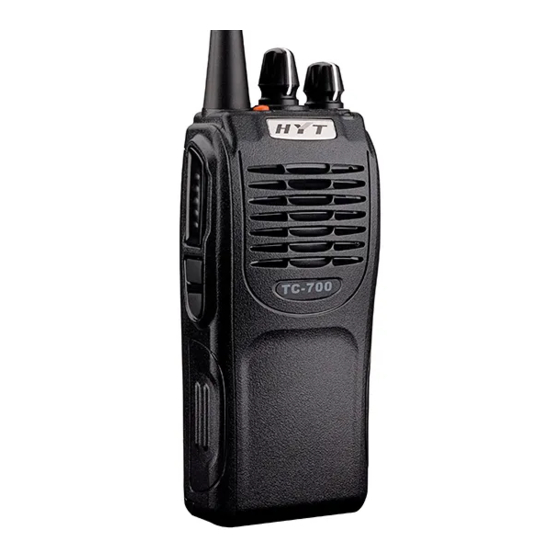
TC-700P Service Manual Radio Overview (1) PTT (Push-to-Talk) Key (2) SK1 (3) SK2 (4) Antenna Channel (5) Speaker (6) Microphone (7) TK Selector Knob (9) Radio On-Off/Volume (10) LED Indicator (11) Battery Latch (12) Belt Clip Control Knob (13) Accessory Jack... -
Page 4: Software Specifications
TC-700P Service Manual Software Specifications Status Indications Operation/Function LED Indication and Alert Tone To enter Wired Clone mode: The LED on the source radio Wired For the source radio, turn it on while holding down flashes red once upon power-on. - Page 5 TC-700P Service Manual Status of the target radio in Wireless Clone mode The LED glows green during cloning. The LED glows orange if cloning is completed successfully. The LED flashes orange if cloning fails. Power-on (to enter User Mode) The LED flashes green once.
- Page 6 TC-700P Service Manual Description of Modes 1. User Mode It is the conventional communication mode. 2. All Reset Mode In this mode, the tuning values, channel frequencies and function data will be initialized. Please refer to the section “Tuning Description” for details.
-
Page 7: Circuit Description
TC-700P adopts the "soft power-down” feature. The battery supplies voltage B+ via the 3A fuse to TC-700P radio. U601 supplies power to the motor via Q601; U602 supplies 5V (M5V) voltage to the control circuit; U604 supplies 5V (C5V) voltage to the common circuit; U603 supplies T5V, R5V, 5CNS voltage. - Page 8 TC-700P Service Manual Figure 2 Diagram of PLL Circuit (1) PLL Circuit The PLL circuit adopts the second harmonic. The step frequencies available for the circuit are 2.5KHz, 5.0KHz or 6.25KHz. In U101, the 16.8MHz reference oscillator signal is divided into 2.5KHZ, 5.0KHz or 6.25KHz reference frequencies via a counter.
- Page 9 TC-700P Service Manual Figure 3 Diagram of RX Circuit (1) RF AMP & BPF After passing through the TX-RX switch circuit and bandpass filter (BPF) circuit, signals received by the antenna are amplified by the RF amplifier (Q410). Then the amplified signals feed to the bandpass filter to remove unwanted signals, allowing wanted signals to go to the first mixer only.
- Page 10 TC-700P Service Manual audio signal. (6) Squelch Control Circuit Noise signal is derived from the audio signal output by Pin 9 of U403, and is processed by U403 to produce a SQL level. Then the SQL level feeds to CPU (U605), and is compared with the preset level to generate a level which controls AF_MUTE and PA_MUTE.
- Page 11 TC-700P Service Manual The APC circuit stabilizes the output TX power by detecting the drain current of the final-stage amplifier. The voltage comparison circuit (U401 (2/2)) compares the voltage derived from the final-stage current with the preset reference voltage. The APC voltage is proportional to the difference between the auto detection voltage (output by U401 (1/2)) and the reference voltage.
- Page 12 TC-700P Service Manual TX: The signaling generated by MCU is sent to the baseband processor. After mixed with the audio, the signal is sent to VCO. RX: After passing through the baseband processor, the demodulated signaling goes to a filter and then to the MCU for decoding.
- Page 13 TC-700P Service Manual Figure 6 Diagram of Control Circuit This circuit is mainly composed of MCU, EEPROM and etc. The MCU has the following functions: to complete reset initialization according to the programmed features; to check the battery voltage and signals from external keys and to make appropriate processing;...
-
Page 14: Cpu Pins
TC-700P Service Manual CPU Pins Port Name Pin Name Function Remarks Automatic power control /RX bandpass control. P94/DA1 APC/TV Adjust APC and RX bandpass through DA (0-5V). DTMF/2-Tone/5-Tone/Beep/A LARM output (DA generates P93/DA0 TONEO waveform). Cannot output from the speaker. - Page 15 TC-700P Service Manual P7_5/TA2IN SHIFT Shift (PWM) CTCSS / CDCSS P76/TA3O CTC_OUT output to VCO for modulation GPS_In GPS input (PWM) CTCSS / CDCSS P74/TA2O CTC_PLL output to PLL for modulation. Programmable port used for Used for future AUX2 future development.
- Page 16 TC-700P Service Manual P52/RD AK2346 TDATA (MSK data P51/BHE AF_TDATA output) For programming only P50/WR (connected to VCC through a (PROG5) 47K resistor) AK2346 DATA I/O(SDAT) P47/CS3 AF_DIO (output control word or read data) Control power supply P46/CS2 H: supply power;...
- Page 17 TC-700P Service Manual Narrow band control P26/A6 N_CON H: narrow band open; L: narrow band closed. Red light control P25/A5 LEDR H: on; L: off. Green light control P24/A4 LEDG H: on; L: off. P23/A3 EN4 Channel Selector knob 4...
- Page 18 TC-700P Service Manual B indicates the second AK2346 (using AK2346B_DI P01/D1 AK2346B register the same clock with the first AK2346) (for 5-Tone model) B indicates the second AK2346 (using AK2346B_D P00/D0 AK2346B data the same clock with the first AK2346) (for...
-
Page 19: Tc-700P Vhf Parts List 1
TC-700P Service Manual TC-700P VHF Parts List 1 Part No. Description Qty. Ref.No. Print No. 1 3001050000000 Chip resistor 0Ω J 1/16W (RoHS) 1 C284 2 3001050000000 Chip resistor 0Ω J 1/16W (RoHS) 1 C546 3 3001050000000 Chip resistor 0Ω J 1/16W (RoHS) 1 R102 4 3001050000000 Chip resistor 0Ω... - Page 20 TC-700P Service Manual Part No. Description Qty. Ref.No. Print No. 40 3001051010000 Chip resistor 100Ω J 1/16W (RoHS) 1 R113 41 3001051010000 Chip resistor 100Ω J 1/16W (RoHS) 1 R204 42 3001051010000 Chip resistor 100Ω J 1/16W (RoHS) 1 R236 43 3001051010000 Chip resistor 100Ω...
- Page 21 TC-700P Service Manual Part No. Description Qty. Ref.No. Print No. 81 3001051030000 Chip resistor 10KΩ J 1/16W (RoHS) 1 R230 82 3001051030000 Chip resistor 10KΩ J 1/16W (RoHS) 1 R246 83 3001051030000 Chip resistor 10KΩ J 1/16W (RoHS) 1 R248 84 3001051030000 Chip resistor 10KΩ...
- Page 22 TC-700P Service Manual Part No. Description Qty. Ref.No. Print No. 122 3001051040010 Chip resistor 100KΩ J 1/16W (RoHS) 1 R496 123 3001051040010 Chip resistor 100KΩ J 1/16W (RoHS) 1 R497 124 3001051040010 Chip resistor 100KΩ J 1/16W (RoHS) 1 R500 125 3001051040010 Chip resistor 100KΩ...
- Page 23 TC-700P Service Manual Part No. Description Qty. Ref.No. Print No. 163 3001051540000 Chip resistor 150KΩ F 1/16W (RoHS) 1 R428 164 3001051540000 Chip resistor 150KΩ F 1/16W (RoHS) 1 R429 165 3001051540000 Chip resistor 150KΩ F 1/16W (RoHS) 1 R430...
- Page 24 TC-700P Service Manual Part No. Description Qty. Ref.No. Print No. 204 3001052230010 Chip resistor 22KΩ J 1/16W (RoHS) 1 R477 205 3001052230010 Chip resistor 22KΩ J 1/16W (RoHS) 1 R672 206 3001052240000 Chip resistor 220KΩ J 1/16W (RoHS) 1 R121 207 3001052240000 Chip resistor 220KΩ...
- Page 25 TC-700P Service Manual Part No. Description Qty. Ref.No. Print No. 245 3001053930000 Chip resistor 39KΩ J 1/16W (RoHS) 1 R148 246 3001053940000 Chip resistor 390KΩ J 1/16W (RoHS) 1 R266 247 3001054700000 Chip resistor 47Ω J 1/16W (RoHS) 1 R413 248 3001054700000 Chip resistor 47Ω...
- Page 26 TC-700P Service Manual Part No. Description Qty. Ref.No. Print No. 286 3001054730000 Chip resistor 47KΩ J 1/16W (RoHS) 1 R651 287 3001054730000 Chip resistor 47KΩ J 1/16W (RoHS) 1 R652 288 3001054730000 Chip resistor 47KΩ J 1/16W (RoHS) 1 R660 289 3001054740000 Chip resistor 470KΩ...
- Page 27 TC-700P Service Manual Part No. Description Qty. Ref.No. Print No. 327 3005051020010 Integrated resistor 1K J 1/16W (RoHS) 1 RN601 B3I 328 3005051020010 Integrated resistor 1K J 1/16W (RoHS) 1 RN603 B2I 329 3005051020010 Integrated resistor 1K J 1/16W (RoHS)
- Page 28 TC-700P Service Manual Part No. Description Qty. Ref.No. Print No. 368 3101051010030 Chip capacitor 100PF J 50V (RoHS) 1 C656 369 3101051010030 Chip capacitor 100PF J 50V (RoHS) 1 C657 370 3101051010030 Chip capacitor 100PF J 50V (RoHS) 1 C658...
- Page 29 TC-700P Service Manual Part No. Description Qty. Ref.No. Print No. 409 3101051020010 Chip capacitor 1000PF K 50V (RoHS) 1 C405 410 3101051020010 Chip capacitor 1000PF K 50V (RoHS) 1 C406 411 3101051020010 Chip capacitor 1000PF K 50V (RoHS) 1 C410...
- Page 30 TC-700P Service Manual Part No. Description Qty. Ref.No. Print No. 450 3101051020010 Chip capacitor 1000PF K 50V (RoHS) 1 C637 451 3101051020010 Chip capacitor 1000PF K 50V (RoHS) 1 C641 452 3101051020010 Chip capacitor 1000PF K 50V (RoHS) 1 C642...
- Page 31 TC-700P Service Manual Part No. Description Qty. Ref.No. Print No. 491 3101051040060 Chip capacitor 0.1UF K 16V (RoHS) 1 C177 492 3101051040060 Chip capacitor 0.1UF K 16V (RoHS) 1 C215 493 3101051040060 Chip capacitor 0.1UF K 16V (RoHS) 1 C216 494 3101051040060 Chip capacitor 0.1UF K 16V (RoHS)
- Page 32 TC-700P Service Manual Part No. Description Qty. Ref.No. Print No. 532 3101051050000 Chip capacitor 1UF K 6.3V (RoHS) 1 C233 533 3101051050000 Chip capacitor 1UF K 6.3V (RoHS) 1 C235 534 3101051050000 Chip capacitor 1UF K 6.3V (RoHS) 1 C248 535 3101051050000 Chip capacitor 1UF K 6.3V (RoHS)
- Page 33 TC-700P Service Manual Part No. Description Qty. Ref.No. Print No. 573 3101051800010 Chip capacitor 18PF J 50V (RoHS) 1 C455 574 3101051800010 Chip capacitor 18PF J 50V (RoHS) 1 C477 575 3101051800010 Chip capacitor 18PF J 50V (RoHS) 1 C478...
- Page 34 TC-700P Service Manual Part No. Description Qty. Ref.No. Print No. 614 3101054700010 Chip capacitor 47PF J 50V (RoHS) 1 C149 615 3101054700010 Chip capacitor 47PF J 50V (RoHS) 1 C221 616 3101054700010 Chip capacitor 47PF J 50V (RoHS) 1 C229...
- Page 35 TC-700P Service Manual Part No. Description Qty. Ref.No. Print No. 655 3101061500010 Chip capacitor 15PF J 50V (RoHS) 1 C115 656 3101050600010 Chip capacitor 6PF B 50V (RoHS) 1 C133 657 3101050600010 Chip capacitor 6PF B 50V (RoHS) 1 C403 658 3101056830000 Chip capacitor 0.068UF K 6.3V (RoHS)
- Page 36 TC-700P Service Manual Part No. Description Qty. Ref.No. Print No. 696 3210306680000 Multi-layer chip inductor 68nH J 300mA 0.80ohm ( RoHS ) 1 L401 697 3210306680000 Multi-layer chip inductor 68nH J 300mA 0.80ohm ( RoHS ) 1 L402 698 3213306682000 Multi-layer chip inductor 6.8uH K 5mA 1.7Ω Q:35 (RoHS) 1 L103 699 3213306682000 Multi-layer chip inductor 6.8uH K 5mA 1.7Ω...
- Page 37 TC-700P Service Manual Part No. Description Qty. Ref.No. Print No. 737 3303020100020 Switching diode 80V 100mA 0.95V/100mA (RoHS) 1 D710 738 3303020100080 Switching diode 35V 100mA 0.92V/100mA (RoHS) 1 D111 739 3303020100080 Switching diode 35V 100mA 0.92V/100mA (RoHS) 1 D112 740 3303020100080 Switching diode 35V 100mA 0.92V/100mA (RoHS)
- Page 38 TC-700P Service Manual Part No. Description Qty. Ref.No. Print No. 778 3307110100080 LED 15mcd 25mA 2.2V 1.6X0.8mm (RoHS) 1 D605 779 3399990000260 Rectifier diode 10V 15mA 380mV/1mA (RoHS) 1 D418 780 3399990000110 Diode ISR154-400 TE25 SOD-106 (RoHS) 1 D601 781 3308250100000 Diode 1A 0.6Ω/10mA (RoHS) 1 D417 782 3499000000140 N-JFET VGS:15V VGSoff:-1.4V IDSS:50mA (RoHS)
- Page 39 TC-700P Service Manual Part No. Description Qty. Ref.No. Print No. 819 3406001000090 NPN transistor 2SC4988FRTR-E 9V 100mA (RoHS) 1 Q402 820 3515990000000 N-MOSFET VDS:16V ID:3.8A VGS(th):0.4V (RoHS) 1 Q409 821 3504990000010 PA MOSFET VDS:30V ID:600mA VGS(th):1.8V 1.4W (RoHS) 1 Q404...
- Page 40 TC-700P Service Manual Part No. Description Qty. Ref.No. Print No. 860 3001055620000 Chip resistor 5.6KΩ J 1/16W (RoHS) 1 R206 861 3001052030000 Chip resistor 20KΩ J 1/16W (RoHS) 1 R232 862 3001052030000 Chip resistor 20KΩ J 1/16W (RoHS) 1 R256 863 3001055610000 Chip resistor 560Ω...
- Page 41 916 41007801001D0 PCB VHF main board 4P 111.8mm*46.8mm*1.2mm D (RoHS) 917 3210406331000 Multi-layer chip inductor 330nH K 35mA 0.85ohm (RoHS) 1 L405 918 1616100001420 Semi-finished embedded software of HYT conventional portable radio (RoHS) 919 3101051040010 Chip capacitor 0.1UF Z 25V (RoHS) 1 C631 B4G...
-
Page 42: Tc-700P Uhf Parts List 1
TC-700P Service Manual TC-700P UHF Parts List 1 Part No. Description Qty. Ref.No.Print No. 1 3001050000000 Chip resistor 0Ω J 1/16W (RoHS) C284 2 3001050000000 Chip resistor 0Ω J 1/16W (RoHS) R102 3 3001050000000 Chip resistor 0Ω J 1/16W (RoHS) R140 4 3001050000000 Chip resistor 0Ω... - Page 43 TC-700P Service Manual Part No. Description Qty.Ref.No. P rint No 44 3001051020010 Chip resistor 1KΩ J 1/16W (RoHS) R133 45 3001051020010 Chip resistor 1KΩ J 1/16W (RoHS) R142 46 3001051020010 Chip resistor 1KΩ J 1/16W (RoHS) R205 47 3001051020010 Chip resistor 1KΩ J 1/16W (RoHS) R209 48 3001051020010 Chip resistor 1KΩ...
- Page 44 TC-700P Service Manual Part No. Description Qty.Ref.No. P rint No 89 3001051030000 Chip resistor 10KΩ J 1/16W (RoHS) R295 90 3001051030000 Chip resistor 10KΩ J 1/16W (RoHS) R308 91 3001051030000 Chip resistor 10KΩ J 1/16W (RoHS) R309 92 3001051030000 Chip resistor 10KΩ J 1/16W (RoHS) R310 93 3001051030000 Chip resistor 10KΩ...
- Page 45 TC-700P Service Manual Part No. Description Qty.Ref.No. P rint No 134 3001051240000 Chip resistor 120KΩ J 1/16W (RoHS) R147 135 3001051240000 Chip resistor 120KΩ J 1/16W (RoHS) R289 136 3001051510000 Chip resistor 150Ω J 1/16W (RoHS) R107 137 3001051510000 Chip resistor 150Ω J 1/16W (RoHS) R459 138 3001051510000 Chip resistor 150Ω...
- Page 46 TC-700P Service Manual Part No. Description Qty.Ref.No. P rint No 179 3001052220000 Chip resistor 2.2KΩ J 1/16W (RoHS) R143 180 3001052220000 Chip resistor 2.2KΩ J 1/16W (RoHS) R151 181 3001052220000 Chip resistor 2.2KΩ J 1/16W (RoHS) R434 182 3001052220000 Chip resistor 2.2KΩ J 1/16W (RoHS) R462 183 3001052220000 Chip resistor 2.2KΩ...
- Page 47 TC-700P Service Manual Part No. Description Qty.Ref.No. P rint No 224 3001053340000 Chip resistor 330KΩ J 1/16W (RoHS) R112 225 3001053340000 Chip resistor 330KΩ J 1/16W (RoHS) R247 226 3099080398000 Chip resistor 0.39Ω J 1/4W (RoHS) R422 227 3099080398000 Chip resistor 0.39Ω J 1/4W (RoHS) R423 228 3099080398000 Chip resistor 0.39Ω...
- Page 48 TC-700P Service Manual Part No. Description Qty.Ref.No. P rint No 269 3001054730000 Chip resistor 47KΩ J 1/16W (RoHS) R647 270 3001054730000 Chip resistor 47KΩ J 1/16W (RoHS) R648 271 3001054730000 Chip resistor 47KΩ J 1/16W (RoHS) R649 272 3001054730000 Chip resistor 47KΩ J 1/16W (RoHS) R651 273 3001054730000 Chip resistor 47KΩ...
- Page 49 TC-700P Service Manual Part No. Description Qty.Ref.No. P rint No 314 3005051020000 Integrated resistor 1K J 1/16W (RoHS) 1 RN625 B2H 315 3005051020000 Integrated resistor 1K J 1/16W (RoHS) 1 RN626 B4H 316 3005051020010 Integrated resistor 1K J 1/16W (RoHS)
- Page 50 TC-700P Service Manual Part No. Description Qty.Ref.No. P rint No 359 3101051010030 Chip capacitor 100PF J 50V (RoHS) C675 360 3101051010030 Chip capacitor 100PF J 50V (RoHS) C676 361 3101051010030 Chip capacitor 100PF J 50V (RoHS) C677 362 3101051010030 Chip capacitor 100PF J 50V (RoHS)
- Page 51 TC-700P Service Manual Part No. Description Qty.Ref.No. P rint No 404 3101051020010 Chip capacitor 1000PF K 50V (RoHS) C621 405 3101051020010 Chip capacitor 1000PF K 50V (RoHS) C624 406 3101051020010 Chip capacitor 1000PF K 50V (RoHS) C626 407 3101051020010 Chip capacitor 1000PF K 50V (RoHS)
- Page 52 TC-700P Service Manual Part No. Description Qty.Ref.No. P rint No 449 3101051040060 Chip capacitor 0.1UF K 16V (RoHS) C239 450 3101051040060 Chip capacitor 0.1UF K 16V (RoHS) C240 451 3101051040060 Chip capacitor 0.1UF K 16V (RoHS) C246 452 3101051040060 Chip capacitor 0.1UF K 16V (RoHS) C268 453 3101051040060 Chip capacitor 0.1UF K 16V (RoHS)
- Page 53 TC-700P Service Manual Part No. Description Qty.Ref.No. P rint No 494 3101051050000 Chip capacitor 1UF K 6.3V (RoHS) C293 495 3101051050000 Chip capacitor 1UF K 6.3V (RoHS) C294 496 3101051050000 Chip capacitor 1UF K 6.3V (RoHS) C295 497 3101051050000 Chip capacitor 1UF K 6.3V (RoHS)
- Page 54 TC-700P Service Manual Part No. Description Qty.Ref.No. P rint No 539 3101052240010 Chip capacitor 0.22UF Z 10V (RoHS) C212 540 3101052240010 Chip capacitor 0.22UF Z 10V (RoHS) C236 541 3101062250000 Chip capacitor 2.2UF K 10V (RoHS) C512 542 3101052700000 Chip capacitor 27PF J 50V (RoHS)
- Page 55 TC-700P Service Manual Part No. Description Qty.Ref.No. P rint No 584 3101054710010 Chip capacitor 470PF K 50V (RoHS) C152 585 3101054710010 Chip capacitor 470PF K 50V (RoHS) C160 586 3101054710010 Chip capacitor 470PF K 50V (RoHS) C172 587 3101054710010 Chip capacitor 470PF K 50V (RoHS)
- Page 56 TC-700P Service Manual Part No. Description Qty.Ref.No. P rint No 629 3101063690000 Chip capacitor 3.6PF B 50V (RoHS) C117 630 3101063690000 Chip capacitor 3.6PF B 50V (RoHS) C526 631 3101064590010 Chip capacitor 4.5PF C 50V (RoHS) C107 632 3101064590010 Chip capacitor 4.5PF C 50V (RoHS)
- Page 57 TC-700P Service Manual Part No. Description Qty.Ref.No. P rint No 674 3210306339000 Chip inductor 3.3nH S 500mA 0.15ohm (RoHS) L119 675 3210306339000 Chip inductor 3.3nH S 500mA 0.15ohm (RoHS) L126 676 3210306339000 Chip inductor 3.3nH S 500mA 0.15ohm (RoHS) l406 677 3210306330000 Chip inductor 33nH J 300mA 0.60ohm RoHS )...
- Page 58 TC-700P Service Manual Part No. Description Qty.Ref.No. P rint No 719 3303030100010 Switching diode 80V 100mA 1V/100mA (RoHS) D603 720 3303030300000 Schottky barrier diode 40V 30mA 0.26V/1mA (RoHS) D202 721 3303030300000 Schottky barrier diode 40V 30mA 0.26V/1mA (RoHS) D203 722 3303030300000 Schottky barrier diode 40V 30mA 0.26V/1mA (RoHS) D204 723 3303030300000 Schottky barrier diode 40V 30mA 0.26V/1mA (RoHS)
- Page 59 TC-700P Service Manual Part No. Description Qty.Ref.No. P rint No 764 3403008000030 BRT Vce:50V VIoff:0.5V VIon:3V 100mA (RoHS) Q403 765 3403008000050 BRT Vce:50V VIoff:0.3V VIon:1.4V 100mA (RoHS) Q615 766 3403008000070 BRT Vce:50V VIoff:0.5V VIon:3V 100mA (RoHS) Q602 767 3403008000070 BRT Vce:50V VIoff:0.5V VIon:3V 100mA (RoHS) Q608 768 3403008000070 BRT Vce:50V VIoff:0.5V VIon:3V 100mA (RoHS)
- Page 60 TC-700P Service Manual Part No. Description Qty.Ref.No. P rint No 809 4099000000050 Fuse 046602.5NR 32V 2.5A (RoHS) F601 810 4301080000020 Momentary contact switch 2VDC 0.05A (RoHS) 1 SW719 B4A 811 5202010100010 FPC connector 10Pin 0.50mm (RoHS) J701 812 5202020100040 FPC connector 20Pin 0.50mm (RoHS) J602 813 5207014200020 FPC connector 14pin 0.5mm female (RoHS)
- Page 61 X401 869 3305180300000 Diode 100mA max 1Ω (RoHS) D403 870 1616100001420 Semi-finished embedded softw are of HYT conventional portable radio (RoHS) 871 3101051040010 Chip capacitor 0.1UF Z 25V (RoHS) C631 872 41007801002C0 PCB UHF main board 4P 111.8mm*46.8mm*1.2mm C (RoHS) 873 3001051820000 Chip resistor 1.8KΩ...
- Page 62 TC-700P Service Manual Part No. Description Qty.Ref.No. P rint No 899 3212106221000 Chip inductor 220nH J 300mA 0.4ohm (RoHS) L102 900 3213212150000 Wire-wound chip inductor 15nH J 480mA 0.29Ω (RoHS) L404 901 3213306682000 Chip inductor 6.8uH K 5mA 1.7Ω (RoHS) L103 902 3213306682000 Chip inductor 6.8uH K 5mA 1.7Ω...
-
Page 63: Tuning Description
TC-700P Service Manual Tuning Description Required Test Instruments (1) Communication Test Set 1 set (2) Scanner 1 set (3) 3A/10V Power Supply 1 set (4) Digital Voltmeter 1 set (5) 3A Ammeter 1 set Preparations Reset Your Radio (1) Entering All Reset mode Hold down SK1 + SK2 for two seconds while powering on the radio. - Page 64 TC-700P Service Manual 2. CH: RX low freq. TC104 Check >0.4V Tuning Procedures To enter the mode Hold down TK + SK2 for two seconds while powering on the radio. Then release them, and your radio will enter manual tuning mode.
- Page 65 TC-700P Service Manual RX - {RX3}; Frequency Table for Five-point Tuning Freq. F1 (MHz) F2 (MHz) F3 (MHz) F4 (MHz) F5 (MHz) (MHz) 136~174 145.5 164.5 TX1: TX2: TX3: TX4: TX5: 136.15 145.65 155.15 164.65 173.85 RX1: RX2: RX3: RX4: RX5: 350~390...
- Page 66 TC-700P Service Manual TX Max. Enter tuning mode, PTT: increase Tune the frequency Audio Dev. select channel 5 and SK1: decrease deviation to Communicati make 3-point tunings of 4.0KHz±0.1KHz on Test Set Wide band, 1-point (wideband), TX TEST tunings of Medium band, 3.2KHz±0.1KHz...
- Page 67 TC-700P Service Manual CDCSS Dev Enter tuning mode, PTT: increase Tune the frequency select channel 9 and SK1: decrease deviation to make 3-point tunings of 750±50Hz Wide band, 1-point (wideband), tunings of Medium band, 600±50Hz (medium and 3-point tunings of band) and 400±50Hz...
- Page 68 TC-700P Service Manual 5-Tone/ Enter tuning mode, PTT: increase Tune the frequency 2-Tone select channel 13 and SK1: decrease deviation to Deviation make 3-point tunings of 3.2±0.2KHz Wide band, 1-point (wideband), tunings of Medium band, 2.5±0.2KHz (medium and 3-point tunings of band) and Narrow band.
- Page 69 TC-700P Service Manual (2) Receiver Tuning Items Condition Test Method Purpose (second Instrument group) Enter tuning mode, PTT: increase When level is Sensitivity select channel 1 for the SK1: decrease tuned to -119dBm, second group and make SINAD≥12dB. 5-point tunings of Wide band.
- Page 70 TC-700P Service Manual Sql 3 Level Enter tuning mode, PTT: save When the level is Close select channel 4 for the adjusted to second group and make -124dBm, press 5-point tunings of Wide PTT to save the band, 1-point tunings for current value.
- Page 71 TC-700P Service Manual High RSSI Enter tuning mode, PTT: save When the level is Level select channel 8 for the adjusted to (5-Tone second group and make -70dBm, press only) 3-point tunings of Wide PTT to save the band, 1-point tunings of current value.
-
Page 72: Troubleshooting Flow Chart
TC-700P Service Manual Troubleshooting Flow Chart MCU Check Check the Normal power-on The RF circuit can’t alert tone? be driven. control circuit Speaker works well? Replace the speaker 9.8304 MHz Read and write Reset works normally? available? Check reading & writing circuit... - Page 73 TC-700P Service Manual Check Power supply is Replace Q104 normal? Oscillator Check Replace CV voltage in Rx is if Q102 works Q102 normal? well. Check if Q105 outputs Check Q105 normally? Check if feedback is Check Q107 normal. Check Check power if 16.8MHz...
-
Page 74: Transmitter Circuit
TC-700P Service Manual Transmitter Circuit No output power Power supply Check power works well? supply circuit The current is Control voltage is Check Q607 normal? normal? High Check transistor, Check drive offset voltage & stage low pass network Repair the... -
Page 75: Receiver Circuit
TC-700P Service Manual Receiver Circuit No receive Power Control Supply of audio IC voltage PA_MUTE Replace Q615 is normal? is normal? Replace U609 Baseband Baseband IC Replace IC outputs inputs normally? AK2346 normally? U403 outputs Check U201 normally? Check volume... -
Page 76: Disassembly And Assembly For Repair
TC-700P Service Manual Disassembly and Assembly for Repair (See Figure 1) Removing the Radio Case Remove the Radio On-Off /Volume Control knob ① and the Channel Selector knob ②. Lift the chassis by its bottom, and pull it out of the radio case ③. - Page 77 TC-700P Service Manual (See Figures 3 & 4) Removing the TX and RX Units 1. Screw out the waterproof rings ⑧ and the nuts ⑨ (see Figure 3). Figure 3 ○ 2. Remove the screws ⑩ locking PCB and the screw 11 locking PTT key.
- Page 78 TC-700P Service Manual Precautions for Assembly (see Figure 5) 1. Make sure the waterproof ring surrounding the chassis is well fitted into the slot ①. 2. Mount the speaker into an appropriate location ② on the radio case. The speaker must be fully inserted.
-
Page 79: Exploded View
TC-700P Service Manual Exploded View... -
Page 80: Tc-700P Parts List 2
TC-700P Service Manual TC-700P Parts List 2 Qty. Part No. Description 6000135000000 PTT key cover (RoHS) 6100068000000 Silicone rubber PTT key (RoHS) 6100350000000 Emergency Key (RoHS) 7500210000000 3M adhesive tape (9448) for light guide (RoHS) 6000609000000 Light guide (RoHS) 7400208000000... -
Page 81: Packing
TC-700P Service Manual Packing... -
Page 82: Tc-700P Vhf Pcb View
TC-700P VHF PCB View Top Layer... - Page 83 TC-700P VHF PCB View Bottom Layer...
-
Page 84: Tc-700P Uhf Pcb View
TC-700P UHF PCB View Top Layer... - Page 85 TC-700P UHF PCB View Bottom Layer...
-
Page 86: Tc-700P Block Diagram
TC-700P Block Diagram CTC_OUT 2Tone DTMF SHIFT AK2346 DRIVE AMP FINAL AMP BUFF AMP LO SW ANT SW RIPPLE FILTER CTC/CDC Q409 D401 Q104 Q401 Q402 Q404 D403 Q106 RQA00 D402 Q610 TXD/RXD 2SC5108 2SC4988 RD01 MA2Z077 2SC4617 2SC5108 Q101Q103... -
Page 87: Tc-700P Vhf Schematic Diagram
TC-700P VHF Schematic Diagram (AF AMP&EXT Interface Circuit) AFAMP&EXT Interface Circuit C685 C685 47u/16V 47u/16V R666 R666 470k 470k U609 U609 C680 C680 C679 C679 C678 C678 C677 C677 C676 C676 C675 C675 C674 C674 C673 C673 R667 R667 TDA8547TS... - Page 88 TC-700P VHF Schematic Diagram (Baseband Circuit) R204 R204 R208 R208 VOL_OUT AUDIO_AMP R305 R305 R220 R220 R290 R290 C216 C216 4.7k 4.7k 0.1uF 0.1uF R207 R207 R211 R211 R210 R210 TONEO R209 R209 C280 C280 C281 C281 R292 R292 0.01uF 0.01uF...
- Page 89 TC-700P VHF Schematic Diagram (MCU Circuit) MCU Circuit R642 R642 R622 R622 AF_DIO R659 R659 U610 U610 SAVE HOLD AUX_E AT25256A/AT24C512 AT25256A/AT24C512 R623 R623 LED_EN U606 U606 SWB+ EECLK AT25256A/AT24C512 AT25256A/AT24C512 EEP_SI R626 R626 RXD0 HOLD 220K 220K TXD0 R625...
- Page 90 TC-700P VHF Schematic Diagram (PLL&VCO Circuit) PLL&VCO Circuit C149 C149 L122 L122 D113 D113 C150 C150 C154 C154 L120 L120 C183 C183 C151 C151 MA2S077 MA2S077 470p 470p Q111 Q111 DTA114EE DTA114EE R128 R128 L126 L126 C153 C153 D114 D114...
- Page 91 TC-700P VHF Schematic Diagram (Power Circuit) J601 J601 BATTSEL C605 C605 F601 F601 Q601 Q601 1000pF 1000pF 2SA1745 2SA1745 J604 J604 R620 R620 FUSE FUSE L601 L601 BATTSEL BATTSEL 220K 220K C601 C601 D601 D601 U601 U601 1000pF 1000pF C602...
- Page 92 TC-700P VHF Schematic Diagram (TX/RX Circuit) TX/RX Circuit C444 C444 C445 C445 C447 C447 J401 J401 1.5PF 1.5PF ANTENNA ANTENNA C520 C520 R431 R431 C437 C437 D403 D403 C442 C442 L436 L436 L437 L437 L438 L438 82PF 82PF MA2Z077 MA2Z077...
-
Page 93: Tc-700P Uhf Schematic Diagram
TC-700P UHF Schematic Diagram (AF AMP&EXT Interface Circuit) AFAMP&EXT Interface Circuit C685 C685 R666 R666 560k 560k U609 U609 C680 C680 C679 C679 C678 C678 C677 C677 C676 C676 C675 C675 C674 C674 C673 C673 R667 R667 TDA8547TS TDA8547TS 100p... - Page 94 TC-700P UHF Schematic Diagram (Baseband Circuit) R204 R204 R208 R208 VOL_OUT AUDIO_AMP R305 R305 R220 R220 R290 R290 C216 C216 4.7k 4.7k 0.1uF 0.1uF R207 R207 R211 R211 R210 R210 TONEO R209 R209 R245 R245 C280 C280 C281 C281 0.01uF 0.01uF...
- Page 95 TC-700P UHF Schematic Diagram (MCU Circuit) MCU Circuit R683 R683 R659 R659 R682 R682 AF_DIO U610 U610 AT25256A/AT24C512 AT25256A/AT24C512 SAVE HOLD AUX_E LED_EN R681 R681 EEP_ID U606 U606 SWB+ EECLK AT25256A/AT24C512 AT25256A/AT24C512 EEP_SI R626 R626 RXD0 HOLD 220K 220K TXD0...
- Page 96 TC-700P UHF Schematic Diagram (PLL&VCO Circuit) PLL&VCO Circuit C149 C149 L122 L122 D113 D113 C150 C150 C154 C154 L120 L120 MA2S077 MA2S077 0.5p 0.5p C151 C151 R137 R137 Q111 Q111 DTA114EE DTA114EE R128 R128 D114 D114 C156 C156 L121 L121...
- Page 97 TC-700P UHF Schematic Diagram (Power Circuit) J601 J601 BATTSEL C605 C605 F601 F601 Q601 Q601 1000pF 1000pF 2SA1745 2SA1745 J604 J604 R620 R620 FUSE FUSE L601 L601 BATTSEL BATTSEL 220K 220K C601 C601 D601 D601 U601 U601 1000pF 1000pF C602...
- Page 98 TC-700P UHF Schematic Diagram (TX/RX Circuit) TX/RX Circuit C444 C444 C445 C445 C447 C447 J401 J401 C520 C520 1.5p 1.5p 2.4p 2.4p ANTENNA ANTENNA C526 C526 R431 R431 C437 C437 D403 D403 C442 C442 3.6p 3.6p 100p 100p HVU131 HVU131...
-
Page 99: Specifications
TC-700P Service Manual Specifications General VHF: 136-174MHz Frequency Range UHF: 400-470MHz Channel Capacity Channel Spacing 25 KHz/20KHz/12.5KHz Operating Voltage 7.4V Battery 1700mAh Li-Ion battery Battery Life (5-5-90 duty cycle) 12 hours Operating Temperature -25℃~+60℃ Dimensions (H×W×D) 124×54×35mm (with battery, without antenna) Weight (with antenna &... - Page 100 TC-700P Service Manual Hytera endeavors to achieve the accuracy and completeness of this manual, but no warranty of accuracy or reliability is given. All the specifications and designs are subject to change without notice due to continuous technology development. Changes which may occur after publication are highlighted by Revision History contained in Service Manual.
Need help?
Do you have a question about the TC-700P and is the answer not in the manual?
Questions and answers