Table of Contents
Advertisement
Quick Links
Advertisement
Table of Contents

Related Manuals for HYT TM-600


Summary of Contents for HYT TM-600
- Page 1 8130M60000010 2008-03-05...
-
Page 2: Table Of Contents
TM-600 SERVICE MANUAL CONTENTS Revision History-----------------------------------------------------------------------------------------------2 General-----------------------------------------------------------------------------------------------------------2 Radio Overview------------------------------------------------------------------------------------------------4 Software Specification--------------------------------------------------------------------------------------6 Circuit Description------------------------------------------------------------------------------------------15 Semiconductor Data----------------------------------------------------------------------------------------20 Component Description-----------------------------------------------------------------------------------24 Parts List 1-----------------------------------------------------------------------------------------------------25 Tuning Description------------------------------------------------------------------------------------------63 Terminal Function-------------------------------------------------------------------------------------------75 Trouble-shooting Flow Chart ---------------------------------------------------------------------------78 Disassembly and Assembly for Repair---------------------------------------------------------------82 Exploded View------------------------------------------------------------------------------------------------85 Parts List 2-----------------------------------------------------------------------------------------------------86 Packing---------------------------------------------------------------------------------------------------------87 PCB View-------------------------------------------------------------------------------------------------------88... -
Page 3: Revision History
TM-600 SERVICE MANUAL Revision History Version Date Contents Revised 8130M60000000 March, 2007 Initial release 8130M60000010 March, 2008 Circuit Update: 1.Add new frequency(4 70-520MHz 350-400MHz 440-470MHz) 2.update content of tuning description, parts list 1, schematic diagram and PCB view. 3.Add the new definition for J503 (second development interface) in Semiconductor Data. - Page 4 TM-600 SERVICE MANUAL Operation Safety Guidelines For vehicles equipped with electronic anti-skid braking systems, electronic ignition systems or electronic fuel injection systems, interferences may occur during the radio transmission. If the foregoing electronic equipments are installed on your vehicle, please contact your dealer for further assistance to make sure that the radio transmission will not interfere with these equipments.
-
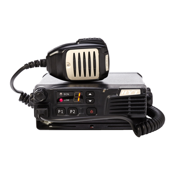
Page 5: Radio Overview
Used to connect external speaker and only available for the plug of 3.5 mm (Please refer to Test Cable for Speaker Output of Tuning Mode for details). ③ Power Inlet Adopt HYT-authorized DC power cable and 13.6 V DC power. - Page 6 TM-600 SERVICE MANUAL ④ Antenna Pedestal Used to connect external antenna. Microphone 8-segment LED Display Figure 1 8-segment LED...
-
Page 7: Software Specification
TM-600 SERVICE MANUAL Software Specification Frame of Radio Modes User Mode Conventional Mode Tuning Mode Model Set Mode Wired Clone Mode Clone Mode Wireless Clone Mode PC Mode Keypad Entry for Mode Startup Mode Display Operation Remarks User Mode Channel Number... - Page 8 TM-600 SERVICE MANUAL MONI D: MONI D CH Number Carrier Squelch-Toggle User Selectable Tone UST Number (0 .-9.) CTCSS/CDCSS Signalling Select 2-tone 2-tone Number (0.-9.) Select 2-Tone encode TX Power CH Number Switch TX power Scan ● Scan Add/Delet ●...
- Page 9 TM-600 SERVICE MANUAL Emergency call EmergencyCH Number(1- 8) Emergency call HDC Encode Call List Number HDC Call Lone worker L. or L Lone worker Whisper R. or R Whisper AUX A None AUX A AUX B None AUX B CH Number...
- Page 10 TM-600 SERVICE MANUAL MONI C: MONI C CH Number Carrier Squelch-Momentary MONI D: MONI D CH Number Carrier Squelch-Toggle User Selectable UST Number(0.-9.) CTCSS/CDCSS signalling Tone Sel 2-tone 2-tone Number(0.-9.) Select 2-Tone encode TX Power CH Number Switch TX Power Scan ●...
- Page 11 TM-600 SERVICE MANUAL MSK Deviation Single Tone Deviation RX sensitivity Squelch On Level 9 Squelch On Level 3 Squelch Off Level 9 Squelch Off Level 3 Clone Mode Data can be transferred from radio to radio either by wired cloning or wireless cloning.
-
Page 12: Tuning Mode
TM-600 SERVICE MANUAL Note: Clone Mode can be enabled/disabled by your local dealer. Wired clone is accessible only when Clone Mode is enabled. Tuning Mode The operations of Tuning Mode are described as following: 1) Press [P1] to power on the radio. The radio enters Tuning Mode and its LED flashes red twice. - Page 13 TM-600 SERVICE MANUAL Medium Center 3. CTCSS: 67.0Hz Narrowband Center 4. CTCSS: 67.0Hz Center 0. CTCSS: 151.4Hz Wideband 1. CTCSS: 151.4Hz High 2. CTCSS: 151.4Hz Medium Center 3. CTCSS: 151.4Hz Narrowband Center 4. CTCSS: 151.4Hz Center 0. CTCSS: 254.1Hz Wideband 1....
- Page 14 TM-600 SERVICE MANUAL High 6. No signalling Center 0. No signalling SQL 9 Wideband 1. No signalling High 2. No signalling SQL 9 Medium Center 3. No signalling Center 4. No signalling SQL 9 Narrowband 5. No signalling High 6....
- Page 15 TM-600 SERVICE MANUAL RX(MHz) 375.15 350.15 399.85 362.55 387.50 375.00 375.20 375.40 (U4) TX(MHz) 375.00 350.00 400.00 362.50 387.50 375.00 375.20 375.40 RX(MHz) 455.15 440.15 469.85 447.55 462.50 455.00 455.20 455.40 (U5) TX(MHz) 455.00 440.00 470.00 447.50 462.50 455.00 455.20 455.40...
-
Page 16: Circuit Description
TM-600 SERVICE MANUAL Circuit Description Frequency Configuration The receiver utilizes double conversion superheterodyne. The first IF is 49.95MHz and the second is 450KHz. The first local oscillator signal is supplied by PLL circuit. The second (50.4MHz) is generated from the frequency tripling of TCXO (16.8MHz). The PLL circuit generates the frequencies required for transmission. -
Page 17: Transmitter Circuit
TM-600 SERVICE MANUAL to become a 49.95MHz first IF signal. The first IF signal is then fed through crystal filter (IF200) to further remove spurious signals. 3. IF Amplifier The first IF signal is amplified by Q113 and then enters IC102 (TA31136FN), where the signal is mixed again with the second local oscillator signal (50.4MHz) to become a 450KHz second IF signal. -
Page 18: Pll Circuit
TM-600 SERVICE MANUAL 2. RF Driver and Final-stage Power Amplification Circuit The TX-RF signal outputted from Q703 in VCO circuit is amplified by Q101, driver Q110 and Q109, The amplified signal is then fed to IC101 (final-stage amplifier) and passes through LPF before reaching the antenna terminal. - Page 19 TM-600 SERVICE MANUAL Fig 4 Control Circuit 2. Power Supply Power supply of the radio is derived from the battery which supplies battery B+. D135 and D137 are over-voltage protection diodes. Power-on/off can be controlled by software. Fig 5 Power Supply Circuit Vout provides power supply for IC601, IC602 and IC803, which produces 8V, 5V, 3.3V voltage to the...
-
Page 20: Display Circuit
TM-600 SERVICE MANUAL Display Circuit Display circuit is comprised of CPU (IC502), LCD module, 8-segment numeric LED, LED and other components. Radio features are programmable by P1-P4. Data is displayed on the 8-segment LED in alphanumeric form. Fig 6. Display Circuit... -
Page 21: Semiconductor Data
TM-600 SERVICE MANUAL Semiconductor Data 1. Positive Voltage regulator: TA7805F (Power Unit IC602), TA7808S (Power Unit IC601). 2. EEPROM: AT24C256N10SI2.7 (CPU unit IC501) Pin Function Pin No. Name Function 1 to 3 A0 to A2 Address input Serial data Serial clock input... - Page 22 TM-600 SERVICE MANUAL 4. Audio Power Amplifier: TDA7297D (AF Pwr unit IC511) Pin Function Pin No. Name Function PW GND Power ground 1. OUT1+ Output 1+ . OUT1- Output 1- Supply voltage Input 1 Operation switch STAND-BY Operation switch PW GND...
- Page 23 TM-600 SERVICE MANUAL Clock input P85/NMI NMI, use or not P84/INT2 AFRDF Baseband chip MSK receive detect (RDF/FD) P83/INT1 DTMFSTD Unused (left open) P82/INT0 AUX1 Optional circuit board port 1(input) (renamed AUX1) P81/TA4in SB Power switch control H: off L: on...
- Page 24 Ignition sense input H: off L: on [PWR] key input On: L TYPE TM-600/TM610 Selection input H: TM-600 ; L: TM610 Left floating P4 key input On: L (external pull-up resistor) P3 key input On: L (external pull-up resistor) P2 key input...
-
Page 25: Component Description
TM-600 SERVICE MANUAL Component Description 1. TX-RX Unit Ref. No. Part Name Type Description IC101 Power module Power module IC501 AT2408N12.5S EROM IC401 AK2346 Audio processor IC404 TA75W558FU Dual operational amplifier IC403 TC75W51FU Dual operational amplifier IC803 XC62FP3302P Positive voltage regulator... -
Page 26: Parts List
TM-600 SERVICE MANUAL PartsList1 TX-RX Unit(UHF) TM-600 Parts List 1(Tx-Rx Unit) Material No. Description Qty. Ref.No. Address Remark 3001050000000 Chip resistor 0402 0Ω C404 3001050000000 Chip resistor 0402 0Ω R106 3001050000000 Chip resistor 0402 0Ω R110 3001050000000 Chip resistor 0402 0Ω... - Page 27 TM-600 SERVICE MANUAL 49 3001051020010 Chip resistor 0402 1K Ω R609 50 3001051020010 Chip resistor 0402 1K Ω R610 51 3001051020010 Chip resistor 0402 1K Ω R612 52 3001051020010 Chip resistor 0402 1K Ω R632 53 3001051020010 Chip resistor 0402 1K Ω...
- Page 28 TM-600 SERVICE MANUAL 101 3001051050020 Chip resistor 0402 1MΩ R901 102 3001051230000 Chip resistor 0402 12KΩ R152 103 3001051230000 Chip resistor 0402 12KΩ R471 104 3001051520000 Chip resistor 0402 1.5KΩ R151 105 3001051530000 Chip resistor 0402 15KΩ R111 106 3001051530000 Chip resistor 0402 15KΩ...
- Page 29 TM-600 SERVICE MANUAL 153 3001053330010 Chip resistor 0402 33KΩ R421 154 3001053330010 Chip resistor 0402 33KΩ R433 155 3001053330010 Chip resistor 0402 33KΩ R436 156 3001053330010 Chip resistor 0402 33KΩ R438 157 3001053330010 Chip resistor 0402 33KΩ R516 158 3001053330010 Chip resistor 0402 33KΩ...
- Page 30 TM-600 SERVICE MANUAL 205 3001058220000 Chip resistor 0402 8.2KΩ R416 U1:400-470MHz 206 3001051830000 Chip resistor 0402 18KΩ U2:450-500MHz 207 3001051830000 Chip resistor 0402 18KΩ U3:470-520MHz 208 3001051530000 Chip resistor 0402 15KΩ U4:350-400MHz 209 3001051830000 Chip resistor 0402 18KΩ U5:440-470MHz 210 3001058230000 Chip resistor 0402 82KΩ...
- Page 31 TM-600 SERVICE MANUAL 257 3001061040010 Chip resistor 0603 100K Ω R135 258 3001061040010 Chip resistor 0603 100K Ω R136 259 3001061040010 Chip resistor 0603 100K Ω R559 260 3001061050010 Chip resistor 0603 1MΩ R147 261 3001061220000 Chip resistor 0603 1.2KΩ...
- Page 32 TM-600 SERVICE MANUAL 309 3001162200000 Chip resistor 2010 22 Ω R193 310 3001164720000 Chip resistor 2010 4.7KΩ R552 311 3002996830000 Trimmer resistor(2*2) 68K Ω(+25%) VR801 312 3005051020000 Resistor array 0402 1K*2 CP501 313 3005051020000 Resistor array 0402 1K*2 CP502 314 3005051020000 Resistor array 0402 1K*2...
- Page 33 TM-600 SERVICE MANUAL 361 3101051030020 Chip capacitor 0402 0.01UF C506 362 3101051030020 Chip capacitor 0402 0.01UF C512 363 3101051030020 Chip capacitor 0402 0.01UF C604 364 3101051030020 Chip capacitor 0402 0.01UF C903 365 3101051030020 Chip capacitor 0402 0.01UF C905 366 3101054730000 Chip capacitor 0402 0.047UF...
- Page 34 TM-600 SERVICE MANUAL 413 3101052210010 Chip capacitor 0402 220PF C170 414 3101052210010 Chip capacitor 0402 220PF C171 415 3101052220010 Chip capacitor 0402 2200pF C455 416 3101052700000 Chip capacitor 0402 27PF C502 417 3101052700000 Chip capacitor 0402 27PF C503 418 3101052720000 Chip capacitor 0402 2700PF C460 419 3101052730000 Chip capacitor 0402 0.027UF...
- Page 35 TM-600 SERVICE MANUAL 465 3101060200010 Chip capacitor 0603 2PF C121 U1:400-470MHz 466 3101060200010 Chip capacitor 0603 2PF U2:450-500MHz 467 3101060200010 Chip capacitor 0603 2PF U3:470-520MHz 468 3101060300010 Chip capacitor 0603 3PF U4:350-400MHz 469 3199060758000 Chip capacitor 0603 0.75PF U5:440-470MHz 470 3101060300010 Chip capacitor 0603 3PF C813 471 3101060390000 Chip capacitor 0603 0.3PF...
- Page 36 TM-600 SERVICE MANUAL 517 3101061030010 Chip capacitor 0603 0.01UF C227 518 3101061030010 Chip capacitor 0603 0.01UF C228 519 3101061030010 Chip capacitor 0603 0.01UF C242 520 3101061030010 Chip capacitor 0603 0.01UF C606 521 3101061040010 Chip capacitor 0603 0.1UF C135 522 3101061040010 Chip capacitor 0603 0.1UF C145 523 3101061040010 Chip capacitor 0603 0.1UF...
- Page 37 TM-600 SERVICE MANUAL 569 3101066800000 Chip capacitor 0603 68PF C156 570 3101066800000 Chip capacitor 0603 68PF C157 571 3101074730000 Chip capacitor 0805 0.047UF C814 572 3102992000000 Trimmer capacitor 3.2*2.5*1.25mm TC101 573 3102992000000 Trimmer capacitor 3.2*2.5*1.25mm TC102 574 3103994760080 Electrolytic capacitor 2512 47UF±20% C234 575 3103994760080 Electrolytic capacitor 2512 47UF±20%...
- Page 38 TM-600 SERVICE MANUAL 621 3221506601000 Chip ferrite bead 0603 600 Ω L137 622 3221506601000 Chip ferrite bead 0603 600 Ω L501 623 3221506601000 Chip ferrite bead 0603 600 Ω L502 624 3221506601000 Chip ferrite bead 0603 600 Ω L503 625 3221506601000 Chip ferrite bead 0603 600 Ω...
- Page 39 TM-600 SERVICE MANUAL 673 3408002000010 Transistor 2SC3357-T1 Q110 674 3501030000000 FET 2SJ506STR Q512 675 3411002000020 Transistor 2SC5343EG Q801 676 3501020000030 FET 3SK318YB Q111 677 3501020000030 FET 3SK318YB Q112 678 3503020000030 FET 2SK1824 Q403 679 3503020000030 FET 2SK1824 Q405 680 3503020000030 FET 2SK1824...
- Page 40 749 3001051030000 Chip resistor 0402 10KΩ U3:470-520MHz 750 3001051030000 Chip resistor 0402 10KΩ U4:350-400MHz 751 3001051030000 Chip resistor 0402 10KΩ U5:440-470MHz 752 5205015000000 TM-600 15PIN Socket 1251 J503 753 5207032000000 FFC/FPC Connector 52559 J501 754 3101051530010 Chip capacitor 0402 0.015UF K C410 755 3101051530010 Chip capacitor 0402 0.015UF K...
- Page 41 TM-600 SERVICE MANUAL 778 3101062700010 Chip capacitor 0603 27PF C124 U1:400-470MHz 779 3101065690000 Chip capacitor 0603 5.6PF U2:450-500MHz 780 3101065690000 Chip capacitor 0603 5.6PF U3:470-520MHz 781 3101063000010 Chip capacitor 0603 30PF U4:350-400MHz 782 3101065690000 Chip capacitor 0603 5.6PF U5:440-470MHz 783 3101062700010 Chip capacitor 0603 27PF...
- Page 42 TM-600 SERVICE MANUAL 831 3101080200010 Chip capacitor 1206 2pF0V U5:440-470MHz 832 3101084710010 Chip capacitor 1206 470pF C108 833 3101084710010 Chip capacitor 1206 470pF C229 834 3101084710010 Chip capacitor 1206 470pF L130 835 3101080400010 Chip capacitor 1206 4pF0V C103 U1:400-470MHz 836 3101080400010 Chip capacitor 1206 4pF0V...
- Page 43 TM-600 SERVICE MANUAL TX-RX Unit(VHF) TM-600 VHF Parts List 1(Tx-Rx Unit) Material No. Description Qty. Ref.No. Address 3001050000000 Chip resistor 0402 0Ω C404 3001050000000 Chip resistor 0402 0Ω R106 3001050000000 Chip resistor 0402 0Ω R419 3001050000000 Chip resistor 0402 0Ω...
- Page 44 TM-600 SERVICE MANUAL 3001051020010 Chip resistor 0402 1KΩ R476 3001051020010 Chip resistor 0402 1KΩ R503 3001051020010 Chip resistor 0402 1KΩ R504 3001051020010 Chip resistor 0402 1KΩ R505 3001051020010 Chip resistor 0402 1KΩ R506 3001051020010 Chip resistor 0402 1KΩ R582 3001051020010 Chip resistor 0402 1KΩ...
- Page 45 TM-600 SERVICE MANUAL 3001051040010 Chip resistor 0402 100KΩ R801 3001051040010 Chip resistor 0402 100KΩ R806 3001051040010 Chip resistor 0402 100KΩ R820 3001051050020 Chip resistor 0402 1MΩ R118 3001051050020 Chip resistor 0402 1MΩ R119 3001051050020 Chip resistor 0402 1MΩ R120 3001051050020 Chip resistor 0402 1MΩ...
- Page 46 TM-600 SERVICE MANUAL 3001052230010 Chip resistor 0402 22KΩ R466 3001052230010 Chip resistor 0402 22KΩ R829 3001052240000 Chip resistor 0402 220KΩ R437 3001052720000 Chip resistor 0402 2.7KΩ R407 3001052730000 Chip resistor 0402 27KΩ R421 3001053030010 Chip resistor 0402 30KΩ R154 3001053030010 Chip resistor 0402 30KΩ...
- Page 47 TM-600 SERVICE MANUAL 3001054730000 Chip resistor 0402 47KΩ R523 3001054730000 Chip resistor 0402 47KΩ R524 3001054730000 Chip resistor 0402 47KΩ R544 3001054730000 Chip resistor 0402 47KΩ R545 3001054730000 Chip resistor 0402 47KΩ R550 3001054730000 Chip resistor 0402 47KΩ R562 3001054730000 Chip resistor 0402 47KΩ...
- Page 48 TM-600 SERVICE MANUAL 3001061030010 Chip resistor 0603 10KΩ R554 3001061030010 Chip resistor 0603 10KΩ R558 3001061030010 Chip resistor 0603 10KΩ R701 3001061030010 Chip resistor 0603 10KΩ R709 3001061030010 Chip resistor 0603 10KΩ R814 3001061040000 Chip resistor 0603 100KΩ R122 3001061040000 Chip resistor 0603 100KΩ...
- Page 49 TM-600 SERVICE MANUAL 3001065620010 Chip resistor 0603 5.6KΩ R810 3001066830000 Chip resistor 0603 68KΩ R133 3001066830000 Chip resistor 0603 68KΩ R134 3001068230010 Chip resistor 0603 82KΩ R719 3001071800000 Chip resistor 0805 18Ω8W R191 3001072020000 Chip resistor 0805 2KΩ8W R190 3001072200000 Chip resistor 0805 22Ω8W...
- Page 50 TM-600 SERVICE MANUAL 3101051020010 Chip capacitor 0402 1000PF C211 3101051020010 Chip capacitor 0402 1000PF C214 3101051020010 Chip capacitor 0402 1000PF C225 3101051020010 Chip capacitor 0402 1000PF C238 3101051020010 Chip capacitor 0402 1000PF C441 3101051020010 Chip capacitor 0402 1000PF C445 3101051020010...
- Page 51 TM-600 SERVICE MANUAL 3101051040010 Chip capacitor 0402 0.1UF C431 3101051040010 Chip capacitor 0402 0.1UF C440 3101051040010 Chip capacitor 0402 0.1UF C463 3101051040010 Chip capacitor 0402 0.1UF C466 3101051040010 Chip capacitor 0402 0.1UF C504 3101051040010 Chip capacitor 0402 0.1UF C505 3101051040010 Chip capacitor 0402 0.1UF...
- Page 52 TM-600 SERVICE MANUAL 3101053300000 Chip capacitor 0402 33PF C415 3101053300000 Chip capacitor 0402 33PF C423 3101053300000 Chip capacitor 0402 33PF C908 3101053310030 Capacitor 0402 330PF C439 3101054700010 Chip capacitor 0402 47PF C433 3101054700010 Chip capacitor 0402 47PF C435 3101054700010 Chip capacitor 0402 47PF...
- Page 53 TM-600 SERVICE MANUAL 3101061020000 Chip capacitor 0603 1000PF C207 3101061020000 Chip capacitor 0603 1000PF C208 3101061020000 Chip capacitor 0603 1000PF C210 3101061020000 Chip capacitor 0603 1000PF C215 3101061020000 Chip capacitor 0603 1000PF C216 3101061020000 Chip capacitor 0603 1000PF C217 3101061020000...
- Page 54 TM-600 SERVICE MANUAL 3101061050000 Chip capacitor 0603 1UF C514 3101061050020 Chip capacitor 0603 1UF C412 3101061300000 Chip capacitor 0603 13PF C150 3101061500010 Chip capacitor 0603 15PF C204 3101061500010 Chip capacitor 0603 15PF C219 3101061500010 Chip capacitor 0603 15PF C703 3101061500010...
- Page 55 TM-600 SERVICE MANUAL 3102992000000 Trimmer capacitor 3.2*2.5*1.25mm TC702 3103994760080 Electrolytic capacitor 2512 47UF±20% C234 3103994760080 Electrolytic capacitor 2512 47UF±20% C533 3104071040010 Tantalum capacitor 0805 0.1UF C814 3104071050010 Tantalum capacitor 0805 1UF C241 3104071050010 Tantalum capacitor 0805 1UF C417 3104071050010 Tantalum capacitor 0805 1UF...
- Page 56 TM-600 SERVICE MANUAL 3210306820000 Multi-layer chip inductor 0603 82nH L122 3213212103000 Multi-layer chip inductor 1008 10uH L134 3213212272000 Multi-layer chip inductor 1008 2.7uH L705 3213212272000 Multi-layer chip inductor 1008 2.7uH L706 3213212272000 Multi-layer chip inductor 1008 2.7uH L708 3213212272000 Multi-layer chip inductor 1008 2.7uH...
- Page 57 TM-600 SERVICE MANUAL 3303020100020 Switching diode MA2S11100L D803 3303020100060 Switching diode MA3J74200L D101 3303020100060 Switching diode MA3J74200L D102 3303020100060 Switching diode MA3J74200L D117 3303020100060 Switching diode MA3J74200L D401 3303030100010 Switching diode DAN222(TL) D113 3303030100010 Switching diode DAN222(TL) D114 3303030100020 Switching diode DAN235E...
- Page 58 TM-600 SERVICE MANUAL 3403008000010 Transistor DTC114EE(TL) Q518 3403008000010 Transistor DTC114EE(TL) Q602 3403008000010 Transistor DTC114EE(TL) Q604 3403008000010 Transistor DTC114EE(TL) Q706 3408002000010 Transistor 2SC3357 Q109 3408002000010 Transistor 2SC3357 Q110 3499000000140 Transistor 2SK508 Q701 3499000000140 Transistor 2SK508 Q702 3501020000030 FET 3SK318YB Q111 3501020000030...
- Page 59 TM-600 SERVICE MANUAL VCO Unit TM-600 parts List 1(VCO Unit ) Material Number Description Qty. Ref.No. Address Remark 3001051010000 Chip resistor 0402 100Ω R174 3001051030000 Chip resistor 0402 10KΩ R170 3001051030000 Chip resistor 0402 10KΩ R176 3001051510000 Chip resistor 0402 150Ω...
- Page 60 TM-600 SERVICE MANUAL 3101060390000 Chip capacitor 0603 0.3PF U5:440-470MHz 3101060590010 Chip capacitor 0603 0.5PF C709 3101060590010 Chip capacitor 0603 0.5PF C717 3101060600010 Chip capacitor 0603 6PF C713 U1:400-470MHz 3101062490000 Chip capacitor 0603 2.4PF U2:450-500MHz 3101060300010 Chip capacitor 0603 3PF U3:470-520MHz...
- Page 61 TM-600 SERVICE MANUAL 3401002000290 Transistor 2SC4116-GR Q705 3401002000990 Transistor 2SC5108-Y Q101 3401002000990 Transistor 2SC5108-Y Q102 3401002000990 Transistor 2SC5108-Y Q703 3403008000010 Transistor DTC114EE(TL) Q706 3499000000140 Transistor 2SK508 Q701 3499000000140 Transistor 2SK508 Q702 3213212102000 Multi-layer chip inductor 1008 1uH L701 3213212102000 Multi-layer chip inductor 1008 1uH...
- Page 62 TM-600 SERVICE MANUAL Display Unit TM-600 Parts List 1 ( Display Unit ) Material No. Description Qty. Ref.No. Address 3001050000000 Chip resistor 0402 0Ω R344 3001051010000 Chip resistor 0402 100Ω R343 3001051030000 Chip resistor 0402 10KΩ R302 3001051030000 Chip resistor 0402 10KΩ...
- Page 63 Transistor DTC114EE(TL) Q309 3403008000010 Transistor DTC114EE(TL) Q310 3403008000010 Transistor DTC114EE(TL) Q311 3403008000010 Transistor DTC114EE(TL) Q312 3403008000010 Transistor DTC114EE(TL) Q313 4002000000180 Fuse 0603-FF 0467.250NR FP101 4002000000180 Fuse 0603-FF 0467.250NR FP102 5207032000000 FFC/FPC Connector 52559 J302 410M6001000J0 TM-600 Control Panel PCB FR4...
-
Page 64: Tuning Description
TM-600 SERVICE MANUAL Tuning Description Key Functions 1. Front Panel ① Volume Control Knob ② Low Power Indicator ③ Scan Indicator ④ Channel Display Numeric LED ⑤ Channel Up Key ⑥ Channel Down Key ⑦ RX/TX Indicator ⑧ On/Off Key ⑨... - Page 65 TM-600 SERVICE MANUAL Panel Tuning Mode The transceiver is tuned in this mode. 1. To Enter the Panel Tuning Mode Press the [P1] key to turn on the radio and the LED flashed red twice; Press the [P2] to enter the panel tuning mode.
- Page 66 TM-600 SERVICE MANUAL Center CTCSS: 67.0Hz Wide Band CTCSS: 67.0Hz High CTCSS: 67.0Hz Medium Band Center CTCSS: 67.0Hz Narrow Band Center CTCSS: 67.0Hz Center CTCSS: 151.4Hz CTCSS Wide Band CTCSS: 151.4Hz Frequency High CTCSS: 151.4Hz Deviation Medium Band Center CTCSS: 151.4Hz...
-
Page 67: Flow Chart
TM-600 SERVICE MANUAL Level 9 Center No signalling Medium Band Center 0. No signalling Level 9 1. No signalling Narrow Band High 2. No signalling Center No signalling Level 3 No signalling Wide Band High No signalling Level 3 Center... - Page 68 TM-600 SERVICE MANUAL...
- Page 69 TM-600 SERVICE MANUAL [P2] Rx Sensitivity(Low) Sensitivity [P2] Rx Sensitivity(CL) [P2] Rx Sensitivity(Center) [P2] Rx Sensitivity(HC) [P2] Rx Sensitivity(High) [P2] [▲ ] / [▼ ] KEY [P2] Open Squelch(Center) open Squelch 9/3 [P2] Open Squelch(Low) [P2] Open Squelch(High) [P2] Open Squelch(middle...
- Page 70 TM-600 SERVICE MANUAL Test Instrument for Alignment Instrument Method Major Specifications Standard Signal Generator Frequency VHF: 136-174MHz, UHF: 400-470MHz ,450-500MHz, (SSG) Modulation 470 -520MHz ,350-400MHz 440-470MHz Output power Frequency modulation and external modulation 0.1uV to 1mV above Power Meter Input Impedance 50 Ω...
- Page 71 TM-600 SERVICE MANUAL Test Cable for Microphone Input The following test cable is recommended. HOOK To AG Audio MICG VTVM 8 PIN 1:CM 5:PTT/TXD 2:HOOK/RXD 6:GND 3.MIC 7:PSB 8:MBL 4:ME Cautions When Removing or Attaching the Shield Cover 1. When handling with the shield cover, do not damage the components on the TX-RX unit.
- Page 72 TM-600 SERVICE MANUAL 3. Tuning Some items can be tuned in conventional mode and the others in manual adjustment mode. Turn on the power to enter conventional mode. Switch off the power. And then turn on the power while holding down [P1]. The radio enter manual adjustment mode.
- Page 73 TM-600 SERVICE MANUAL Transmitter Measurement Tuning Specification/ Item Condition Test Instrument Terminal Part Method Remarks Not enter tuning Radio 4. TX Tune channel item,but switch to Communication Tune VR801 Error<50Hz Frequency frequency Test Set Tune software High Power: Check High Each CH corresponds setting &...
- Page 74 TM-600 SERVICE MANUAL Radio Tune deviation to Each CH corresponds Communication Use [▲ ], [▼ ] 11. CDCSS 0.75KHz± 0.10KHz (W) to a specific TX freq; Test Set key to set Deviation 0.60KHz± 0.10KHz (M) enter item “ 7" Filter CDCSS 0.37KHz±...
- Page 75 TM-600 SERVICE MANUAL 1. Test Mode, CH: RX Center, Radio manually tune Communication to CH 1(C). Test Set SSG Output: [▲ ] [▼ ] Adjust K301. Set the 2. Test Mode, Press & -113dBm SINAD: Sensitivity CH: RX LO, key to toggle among...
-
Page 76: Terminal Function
TM-600 SERVICE MANUAL Terminal Function 1. Display Unit Pin No. Name Description J301 (To MIC Jack) Serial data input for keypad MIC. HOOK/RXD Hook signal input/ Serial data input. MIC signal input. MIC ground PTT/TXD PTT signal input/ Serial data output. - Page 77 TM-600 SERVICE MANUAL LED3 Channel display control LED6 Channel display control LED4 Channel display control 2. TX-RX Unit Pin No. Name Description J501 (To DISPLAY UNIT) +5V. SB [Power outputs after power switch (13.6V+15%)] +5V. SB [Power outputs after power switch (13.6V+15%)] MICDAT Serial data input for keypad MIC.
- Page 78 TM-600 SERVICE MANUAL RXD1 Serial data output MIC2 External MIC signal output. MIC ground AF-OUT Filtered Audio output. Filtered CTCSS/CDCSS output. MIC signal output MIC signal output Ground Ignition sense input Power input after power switch (13.6V+15%). AUX1 Programmable auxiliary port...
-
Page 79: Trouble-Shooting Flow Chart
TM-600 SERVICE MANUAL Trouble-shooting Flow Chart... - Page 80 TM-600 SERVICE MANUAL...
- Page 81 TM-600 SERVICE MANUAL Receive...
- Page 82 TM-600 SERVICE MANUAL Transmit No output Power supply Check power works normally? supply circuit Current is Check Q603 & Control voltage is normal? Q604 normal? High Check transistor Bias voltage and low pass network Check driver stage. Repair Driver stage is...
-
Page 83: Disassembly And Assembly For Repair
TM-600 SERVICE MANUAL Disassembly and Assembly for Repair Disassembly 1. Power off the radio; disconnect the power cable and screw out the antenna connector. 2. Remove the upper cover. 3. Loosen the 8 screws locking the shield cover and pedestal of the aluminum chassis. Then remove the shield cover and disconnect FFC and speaker connection cable which bind control board PCB and main unit PCB. - Page 84 TM-600 SERVICE MANUAL 6. Use electric iron and screwdriver to take apart the antenna connector, power cable, external board and water-proof ring on this board. 7. Loosen the screws fixing main unit PCB and PA module. Assembly 1. Fix the bracket (main unit) by using four self-tapping screws.
- Page 85 TM-600 SERVICE MANUAL 2. Tighten the four tuning screws (each with one shrapnel and one pad). 3. Plug the connector (Microphone) to the jack (Microphone); when the microphone is not in use, hang it on the bracket (Microphone).
-
Page 86: Exploded View
TM-600 SERVICE MANUAL Exploded View 39 40 41 42... -
Page 87: Parts List 2
TM-600 SERVICE MANUAL Parts List 2 Material No. Material Name Qty. 3608002002090 Power management IC TA7808 6201190000010 PA module shield cover RF PA module 7600028000000 Conductive cloth for PA module shield cover 5205000000280 Speaker Jack 6100144000000 Water-proof ring for external board... -
Page 88: Packing
TM-600 SERVICE MANUAL Packing... -
Page 89: Pcb View
TM-600 UHF PCB View(VCO Unit) - Page 90 TM-600 UHF PCB View(Main Board Unit) Top Layer...
- Page 91 TM-600 UHF PCB View(Main Board Unit) Bottom Layer...
- Page 92 TM-600 VHF PCB View(Main Board Unit) Top Layer...
- Page 93 TM-600 VHF PCB View(Main Board Unit) Bottom Layer...
- Page 94 TM-600 VHF PCB View(Display Unit) Top Layer...
- Page 95 TM-600 VHF PCB View(Display Unit) Bottom Layer...
-
Page 96: Tm-600 Block Diagram
TM-600 Block Diagram TM600 Block Diagram Data Q806 Q804,Q806 Q801 PLL IC Q301-- LED 301 IC 801 Drive AMP Drive AMP final AMP TX/RX SW LED0--7 Q308 D801 Q802,Q803 D105 Q110 Q109 IC101 Q702 50ohm 50ohm D104 16.8MHz IC802 IC104... -
Page 97: Schematic Diagram
TM-600V Schematic Diagram VCO Unit TM-600V 车载台 (B 版 ) VCO 电路 D704 R704 1K R712 Q701 C726 C721 2SK508NV(K52) L710 R715 1SV282 1000P 1000P C702 C704 100N L701 D703 C723 3.3U C706 220P 220P C709 R713 R703 220K C722 C701 1000P TC701... - Page 98 TM-600V Schematic Diagram RF Unit TH101 TM-600V 车载台 (B 版 ) RF 电路 Temp 发射电路 IC101 C236 RA30H1317M 1000p ANTENNA C106 C104 C102 R195 C218 C220 L129 D104 L104 L130 L103 L102 C223 C235 C232 601S UMX9401F C234 Q109 1000P 0.1U R174 2SC3357...
- Page 99 TM-600V Schematic Diagram PLL Unit TM-600V 车载台 (B 版 ) PLL 电路 IC803 XC62FP3302P L803 R808 Vout 601S L801 601S VR801 TP803 C810 C811 C830 R832 R803 4.7u/6.3v 1000p C806 IC802 16.8M 2.2k R807 4.7u/6.3 1000p C807 4.7u/6.3v L802 180K C804 Xout 0.56u...
- Page 100 TM-600V Schematic Diagram AFPr Unit TM-600V 车载台 (B 版 ) AFPr 电路 AF_O R437 220K R440 C447 R436 33k C450 R625 R480 C468 R485 R486 R434 R481 IC402 Q406 BEEP R455 2sk1824 TC75W51FU R488 0.1u C467 R401 R402 R403 DT/2T C448 C444 C449...
- Page 101 TM-600U Schematic Diagram VCO Unit C702 频 Frequency 段 C703 C704 C705 C706 C707 C712 C713 C714 C715 C711 120P 10 P 0.3 P 68 P 10 P 5.6 P U1:400MHz-470MHz 0.3 P 10 P 2.4 P U2:450MHz-500MHz 82 P 10 P 180 P U3:470MHz-520MHz...
- Page 102 TM-600U Schematic Diagram RF Unit 频 Frequency 段 C100 C102 C103 C104 C105 C106 C109 C111 C121 C122 C124 C127 C128 C129 C132 C133 C134 C137 C146 C173 C182 C195 C196 C224 C245 C246 L106 L107 L108 L110 L113 L136 R125 R129 R141 R142 R153 R154 R155 R156 4 P 1 P...
- Page 103 TM-600U Schematic Diagram AFPr Unit 频 段 R406 R412 R413 R414 R416 R418 R440 R446 R461 C436 470K U1:400-470MHz 68K 6.8K 8.2K 180K 180K 0.027U U2:450-500MHz 390K 0.027U 330K 100K 30K 150K U3:470-520MHz 100K 180K 470K 180K 0.027U 6.8K 180K U4:350-400MHz 470K 180K...
- Page 104 TM-600U Schematic Diagram PLL Unit 频 段 Frequency R816 R817 U1:400-470MHz U2:450-500MHz U3:470-520MHz U4:350-400MHz U5:440-470MHz TM-600U 车载台 (B 版 ) PLL 电路 IC803 XC62FP3302P L803 R808 Vout 601S L801 601S VR801 TP803 C810 C811 C831 R832 4.7u/6.3v R803 1000p C806 IC802 16.8M 2.2k 4.7u/6.3...
- Page 105 TM-600 (UHF/VHF) Schematic Diagram Display Unit TM-600(VHF/UHF) 车载台 显示单元电路 R341 R347 1.2K k301 R346 D302 D303 LED304 LED302 LED303 SCN LED HP LED J301 LED301 D304 D305 D306 DPY_7-SEG R332 Q313 DTC114EE R330 R326 R325 R324 R323 R331 Q309 Q310...
- Page 106 TM-600 (UHF/VHF) Schematic Diagram CPU Unit TM-600(VHF/UHF) 车载台 (B 版 ) CPU 电路 SDATA SDATA AFDIR AFDIR RSSI RSSI Type Type AUX2 AUX2 AUX6 AUX6 AUX3 CP523 AUX3 AUX5 AUX5 AUX4 AUX4 1K*2 Apc/Sen Apc/Sen SDATA DT/2T DT/2T 2T/5T 2T/5T...
- Page 107 TM-600 (UHF/VHF) Schematic Diagram AFPwr Unit TM-600(VHF/UHF) 车载台 (B 版 ) AFPwr 电路 Q521 R573 2SK1824 4.7K C537 0.1u R575 R624 C531 Q511 1000P BEEP/ALT C511 R571 R572 D516 D515 2SK1824 Q512 BEEP 22ZR-10D DSM3MA1 2SA1641(S.T) 4.7K 0.1u INT_2 INT_1 0.1U...
- Page 108 TM-600 UHF/VHF Schematic Diagram Power Unit TM-600(VHF/UHF) 车载台 (B 版 ) POWER 电路 IC602 TA7805F Vout IC601 C604 C603 TA7808S 0.01U 4.7U/10V Vout C601 C602 4.7U/16V 0.1U Q601 2SB1132 Q602 DTC114EE R601 R602 C605 1000P 4.7K 2SB1132 Q603 Q604 C607 DTC114EE 10U(for VHF, U1, U2, U3&U5)
-
Page 109: Specifications
Frequency Stability ± 2.5ppm HYT endeavors to achieve the accuracy and completeness of this manual, but no warranty of accuracy or reliability is given. All the specifications and design are subject to change without prior notice due to continuous technology development. Changes which may occur after publication are highlighted by Revision History contained in Service Manual.
Need help?
Do you have a question about the TM-600 and is the answer not in the manual?
Questions and answers