Table of Contents
Advertisement
HYT
Mobile Radio
Contents
Introduction ............................................................................................................................................... 2
Safety Information .................................................................................................................................... 3
Radio Overview ........................................................................................................................................ 5
Software Specification ............................................................................................................................. 8
Circuit Description ................................................................................................................................. 19
Semiconductor Data............................................................................................................................... 24
Component Description......................................................................................................................... 29
Parts List 1 .............................................................................................................................................. 30
Tuning Description ................................................................................................................................. 93
Terminal Function................................................................................................................................. 105
Troubleshooting Flow Chart ............................................................................................................... 108
Disassembly and Reassembly for Repair .......................................................................................... 112
Exploded View ...................................................................................................................................... 115
Parts List 2 ............................................................................................................................................ 116
Packing .................................................................................................................................................. 117
PCB View ............................................................................................................................................... 118
Block Diagram ...................................................................................................................................... 118
Schematic Diagram .............................................................................................................................. 118
Specifications ....................................................................................................................................... 118
1
Advertisement
Table of Contents

Related Manuals for HYT TM-628H


Summary of Contents for HYT TM-628H
-
Page 1: Table Of Contents
Mobile Radio Contents Introduction ............................... 2 Safety Information ............................ 3 Radio Overview ............................5 Software Specification ..........................8 Circuit Description ..........................19 Semiconductor Data..........................24 Component Description......................... 29 Parts List 1 .............................. 30 Tuning Description ..........................93 Terminal Function..........................105 Troubleshooting Flow Chart ....................... -
Page 2: Introduction
Transmit only when people inside and outside the vehicle are at least the minimum distance away from a properly installed, externally mounted antenna. Mobile antenna substitution: Don’t substitute HYT supplied or approved antenna, or excessive radio frequency radiation will result. Please contact your dealer or the manufacturer for further instructions. - Page 3 Mobile Radio ▇ ▇ ▇ ▇ Operation Guidelines For vehicles equipped with electronic anti-skid braking systems, electronic ignition systems or electronic fuel injection systems, interferences may occur during radio transmission. If the foregoing electronic equipments are installed on your vehicle, please contact your dealer for further assistance to make sure that radio transmission will not interfere with these equipments.
-
Page 4: Radio Overview
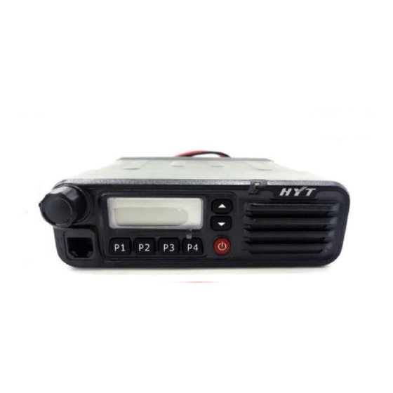
Mobile Radio Radio Overview Front Panel View ① Volume Control Knob Turn the Volume Control Knob clockwise to increase the volume, or counter-clockwise to decrease the volume. ② LCD Please refer to the “LCD Display” section for details. ③ Programmable Functions Keys ([▲] / [▼]) The [▲] / [▼] keys are programmable with auxiliary functions by your dealer. - Page 5 Note: Please refer to “Test Cable for Speaker Output” in “Tuning Description” for details. ③ Power Inlet Used to connect the HYT -authorized DC power cable for input of 13.6V DC power. ④ Antenna Connector Used to connect the external connector.
- Page 6 Mobile Radio ▇ ▇ ▇ ▇ Programmable Function Keys The P1-PF4 and ▲/▼ keys can be programmed with auxiliary functions below: 1. Off 2. CH Up 3. Channel Down 4. Zone Up 5. Zone Down 6. MONI A 7. MONI B 8.
-
Page 7: Lcd Display
Mobile Radio 28. Short Message 29. Rent Time Inquiry 30. AUX A 31. AUX B ▇ LCD Display Figure 1 LCD panel Indicator Description Displays CH number/name, zone number/name, DTMF number, frequency, menu and options, etc. Indicates low power output. Press the Monitor key: 1. - Page 8 Mobile Radio P• Indicates the current channel is the priority channel. indicates priority channel 1, indicates priority channel 2, indicates priority channels 1 and 2.
-
Page 9: Software Specification
HYT Mobile Radio Software Specification Frame of Radio Modes Conventional Mode User Mode Tuning Mode Model Set Mode Wired Clone Mode Clone Mode Wireless Clone Mode PC Mode Keypad Entry for Mode Startup Mode Display Operation Remarks Welcome Screen and then CH... - Page 10 HYT Mobile Radio Panel Tuning Mode You can perform tuning in the following steps: 1) Power on the radio while holding down P1 to enter the tuning mode. 2) Use ▲/▼ to select the tuning item, and press P4 to enter.
- Page 11 HYT Mobile Radio cloned. However, in Factory Clone Mode, all data will be cloned. Connect two radios using a clone cable, and then turn on the target radio. Press P4 on the source radio to start cloning. LED on the source radio glows red, and it begins to transmit data to the target radio.
- Page 12 HYT Mobile Radio Firmware Version Display Mode Power on the radio while holding down P4. The LCD displays the firmware version accordingly. Release P4 to enter User Mode automatically. PC Mode Connect the mobile radio to a PC using a programming cable. Data can be transmitted to the mobile radio and saved in the EEPROM.
- Page 13 HYT Mobile Radio Key Assignment Your dealer may assign one of the following functions to the programmable key (P1/ P2/ P3/ P4/ ▲/ ▼). See the table below for reference. Key Assignment Function Settings Display Remarks P1-P4 No function &...
-
Page 14: Circuit Description
HYT Mobile Radio Short Message Message Menu Short Message Remaining Rental Time Inquiry Remaining Time Inquires about the remaining rental time AUX A AUX A AUX A AUX B AUX B AUX B HOOK/ MONI This option should be selected when palm Hook Check microphone is used. - Page 15 HYT Mobile Radio bandpass frequency range varies with the radio models. The BPF is used to eliminate unwanted signals let only wanted signals go to the mixer. 2.2 First Mixer Circuit The signal output from RF AMP&BPF is mixed with the first LO signal from the PLL circuit at the mixer (D112) to generate a 49.95MHz first IF signal.
- Page 16 HYT Mobile Radio Fig. 2 Transmitter Circuit 3.1 MIC and Modulation Circuit The audio signal from MIC is amplified at IC405, and further amplified, pre-emphasized and encoded at IC 401. It is added with signaling before going to VCO for modulation.
- Page 17 HYT Mobile Radio frequency oscillator (Q701), RX frequency oscillator (Q702), buffer amplifier (Q703), RF amplifier (Q102), PLL IC (IC801), LPF and TX/RX VCO switch (Q704/Q706). In TX mode, IC502 provides the frequency data to and activates PLL IC. Meanwhile, Q704 is turned on to activate TX VCO.
- Page 18 HYT Mobile Radio IC120 (CPU) operates at 9.8304MHz, and controls EEPROM (IC501), RX circuit, TX circuit, control circuit and display circuit, as well as data transmission with peripheral equipment. Fig. 4 Control Circuit 5.2 Reset Circuit The reset circuit consists of a reset IC (CN813LESA) and peripheral circuits. When a breakdown occurs due to change of external voltage, the CPU would automatically reboot your radio through the reset IC (IC901).
- Page 19 HYT Mobile Radio Fig. 5 Power Supply Circuit Vout supplies power for IC601, IC602 and IC803, which generate 8V, 5V and 3.3V voltage respectively to supply the whole circuit. 6. Display Circuit Display circuit comprises CPU (IC502), LCD, LED and other components. Application can be operated manually through programmable keys P1-P4 as well as ▲...
-
Page 20: Semiconductor Data
HYT Mobile Radio Semiconductor Data 1. Positive voltage regulator: TA7805F (Power Unit IC602), TA7808S (Power Unit IC601) 2. EEPROM: CAT24C256WI 256K CATALYST (CPU Unit IC501) 2-1. Pin Function Pin Function Pin No. Name Function 1~3 A0~A2 Address input Ground Serial data input/output... - Page 21 HYT Mobile Radio Audio processor: AK2346 (AFPwr Unit IC404) Pin Function Pin No. Pin Name Function AGNDIN Analog ground input AGND Analog ground output TXIN TX audio signal input TXINO TXA1 feedback output LIMLV Limit level tuning EXTLIMIN External signal input for pre-limiter...
- Page 22 HYT Mobile Radio Operating Switch STAND-BY Operating Switch PW GND Power ground 2 PW GND Power ground 3 SGND Signal ground Input 2 Supply voltage OUT2- Output 2- OUT2+ Output 2+ PW GND Power ground LCD driver: PCF8576DH (Display Unit IC501) Pin No.
- Page 23 HYT Mobile Radio Dual D-type trigger: TC4013BF (AFPwr Unit IC512). RF PLL frequency synthesizer: MB15A02 (PLL Unit IC801). 9. Reset IC: CN813LESA (Reset Unit IC901) 10. CPU: SCM M3062LFGPGP (CPU Unit IC502) Pin Function Pin No. Port Pin Name Function...
- Page 24 HYT Mobile Radio AUX2 AUX 2 Pulled Up Not used (left open) HOLD Not used (left open) (used for downloading) Not used (left open) Not used (left open) External expansion for reading signal (not used) Not used (left open) External expansion for writing signal (not used)
- Page 25 HYT Mobile Radio TYPE selection input Not used (left open) P4 key input L: On (external resistor pulled up) P3 key input L: On (external resistor pulled up) P2 key input L: On (external resistor pulled up) P1 key input...
-
Page 26: Component Description
HYT Mobile Radio Component Description 1. TX-RX Unit Ref. No. Part Name Type Description IC101 Power module Power module IC501 AT2408N12.5S EROM IC401 AK2346 Audio processor IC404 TA75W558FU Dual operational amplifier IC403 TC75W51FU Dual operational amplifier IC803 XC62FP3302P Positive voltage regulator... - Page 27 HYT Mobile Radio Parts List 1 VHF Parts List 1 (Main Board Unit)
- Page 28 HYT Mobile Radio...
- Page 29 HYT Mobile Radio VHF/UHF Parts List 1 (Display Unit)
-
Page 30: Tuning Description
HYT Mobile Radio Tuning Description Key Functions 1. Front Panel ① Volume Control Knob ② LCD Display ③ Programmable Function Keys ▲/▼ ④ LED Indicator ⑤ Speaker ⑥ Power Switch ⑦ Programmable function keys P1/P2/P3/P4 ⑧ Microphone Jack... - Page 31 HYT Mobile Radio Panel Testing Mode 2. Panel Tuning Mode 2-1 Basic Operations in Panel Tuning Mode The transceiver is tuned in this mode. For details on mode selection, see “Software Specifications -> Keypad Entry for Mode Startup”. 2-2 Enter Panel Tuning Mode 1) Power on the radio while holding down P1 to enter the tuning mode, and the LED would flash red twice.
- Page 32 HYT Mobile Radio _C *** No signaling Center Low Power TXLOW _L *** No signaling High _H *** No signaling _C *** No signaling Center _L *** No signaling High _H *** No signaling Maximum Frequency MAXDEV Center M_C ***...
- Page 33 HYT Mobile Radio Center _C *** 0XAAA… _L *** 0XAAA… MSKDEV High _H *** 0XAAA… Deviation Center M_C *** 0XAAA… Center N_C *** 0XAAA… Center _C *** 1KHz _L *** 1KHz Single Tone TONEDEV High _H *** 1KHz Deviation Center...
- Page 34 HYT Mobile Radio N_L *** No signaling High N_H *** No signaling Flow Chart You can perform tuning in the following steps:...
- Page 35 HYT Mobile Radio [P4] Rx Sensitivity (Low) Sensitivity [P4] Rx Sensitivity (CL) [P4] Rx Sensitivity (Center) [P4] Rx Sensitivity (HC) [P4] Rx Sensitivity (High) [P4] [▲]/[▼] KEY [P4] Squelch On (Center) Squelch On 9/3 [P4] Squelch On (Low) [P4] Squelch On (High)
- Page 36 HYT Mobile Radio 3. Instruments for Tuning Instrument Method Specifications Frequency Range VHF: 136-174 MHz; Standard Signal UHF: 400-470 MHz Generator Frequency modulation and external modulation (SSG) Modulation Method 0.1uV and above Power Output Input Impedance Frequency Range VHF: 136-174 MHz;...
- Page 37 HYT Mobile Radio Test Cable for Microphone Input The following test cable is recommended: HOOK To AG Audio VTVM MICG 8 PIN 1:CM 5:PTT/TXD 2:HOOK/RXD 6:GND 3.MIC 7:PSB 4:ME 8:MBL Tuning Instructions The mobile radio can be tuned manually or through PC programming software. For information on manual tuning, see “Software Specifications...
- Page 38 HYT Mobile Radio Method and Procedure: 1) Downloading Connect the mobile radio with PC via programming cable; and turn the radio on. Click “Download” on software interface. Click “Exit” when download is completed. Turn the radio off and remove the programming cable.
- Page 39 HYT Mobile Radio VCO Tuning Measurement Tuning Item Condition Test Specification/ Remarks Terminal Part Method Instrument 1. Power 13.6V DC Supply Note: 1. This radio can be installed in negative ground electrical systems only. Reverse polarity will cause the cable fuse to blow. Check the vehicle ground polarity before installation.
- Page 40 HYT Mobile Radio “_L” or “_H” to tune the tuned for VHF high or low power. high power (not required for UHF). Check deviation at CH “_C”, “_L” and Each channel L/C/H: 4.0±0.2KHz (W) “_H” for wideband Radio corresponds to a...
- Page 41 HYT Mobile Radio Each channel “_C”, “_L” and corresponds to a “_H” indicate the specific TX frequency. widebands of Enter tuning items Use ▲/▼ to each frequency; Communication “CTCL_DEV”,”CTCC_ adjust software Adjust the deviation to “M_C” indicates Test Set 10. CTCSS DEV”...
- Page 42 HYT Mobile Radio “_C”, “_L” and Each channel “_H” indicate the corresponds to a Use ▲/▼ to Communication widebands of specific TX frequency. adjust software Adjust the deviation to Single Test Set each frequency; Enter tuning item settings; press 3.0KHz±0.2KHz...
- Page 43 HYT Mobile Radio 1. Test mode Switch CH: RX Center; manually between Communication switch to CH_1 (C). wideband Test Set SSG output: narrowban -118dBm d (turn Adjust K301 to MOD: 1KHz SINAD: 2. Test mode 18. Sensitivity power on provide rated DEV: ±3KHz (W)
-
Page 44: Terminal Function
HYT Mobile Radio among “_C”, “_L”, “_H”, and Level 9). squelch level. “M_C”, “N_C”, “N_L” and (Note: Do not “N_H”. SSG output: press P4 until -116dBm (Level 9) the LED glows green after P3 is pressed.) 21. Distortion Communication DIS≤5%... - Page 45 HYT Mobile Radio MIC signal output Ground Audio input after tuned by K301 Power switch control signal output RXD2 Serial data output TXD2 Serial data output Audio output after tuned by K301 TYPE Model select P4 signal output P3 signal output...
- Page 46 HYT Mobile Radio TYPE Model select P4 signal output P3 signal output P2 signal output P1 signal output SLED Scan indicator PLED Low power indicator RLED TX indicator control GLED RX indicator control LED1 Channel display control LED7 Channel display control...
-
Page 47: Troubleshooting Flow Chart
HYT Mobile Radio Troubleshooting Flow Chart Check Check power supply Normal power circuit of 8C circuit supply? Rx oscillates? And Replace Q706 works Q705 works CV voltage is normal? Q705 normal? normal? Replace Q706 Q703 outputs Check Q703 normally? Normal... - Page 48 HYT Mobile Radio Check Normal Power-on RF circuit can’t Check the alert tone? control circuit be driven Speaker works Replace the well? speaker Read available Check read 9.8304MHz works or not? circuit normally? Reset Replace Q117 works Q117 normally? Pin10 is of...
- Page 49 HYT Mobile Radio Receive Circuit...
- Page 50 HYT Mobile Radio Transmit Circuit Power supply Check power works normally? supply circuit Current is Check Q603 & Control voltage is normal? Q604 normal? High Check transistor Bias voltage and low pass network Check driver stage. Repair Driver stage is...
- Page 51 HYT Mobile Radio PCB View PCB View (Main Board Unit) PCB View (Main Board Unit) VHF/UHF PCB View (Display Unit) Block Diagram Schematic Diagram VHF Schematic Diagram UHF Schematic Diagram Specifications General VHF: 136-174MHz Frequency Range UHF: 400-470MHz Channel Capacity Channel Spacing 25KHz/20KHz/12.5KHz...
- Page 52 All Specifications are tested according to TIA/EIA-603, and subject to change without notice due to continuous development. HYT endeavors to achieve the accuracy and completeness of this manual, but no warranty of accuracy or reliability is given. All the specifications and designs are subject to change without notice due to continuous technology development.
Need help?
Do you have a question about the TM-628H and is the answer not in the manual?
Questions and answers