Table of Contents
Advertisement
Quick Links
Advertisement
Table of Contents

Summary of Contents for Dome DMWS1
-
Page 1: User Manual
Always Connected. Always Covered. Leak Sensor DMWS1 User Manual... -
Page 2: Preface
Preface As this is the full User Manual, a working knowledge of Z-Wave automation terminology and concepts will be assumed. If you are a basic user, please visit www.domeha.com for instructions. This manual will provide in-depth technical information about the Leak Sensor, especially in regards to its compliance to the Z-Wave standard (such as compatible Command Classes, Association Group capabilities, special features, and other information) that will help you maxi- mize the utility of this product in your system. -
Page 3: Table Of Contents
Table of Contents Preface ..........................2 Description & Features ..................... 4 Specifications ........................5 Physical Characteristics ....................6 Inclusion & Exclusion ......................7 Factory Reset & Misc. Functions ..................8 Physical Installation ......................9 LED Behavior ........................11 Button Behavior ....................... 12 Compatible Command Classes .................. -
Page 4: Description & Features
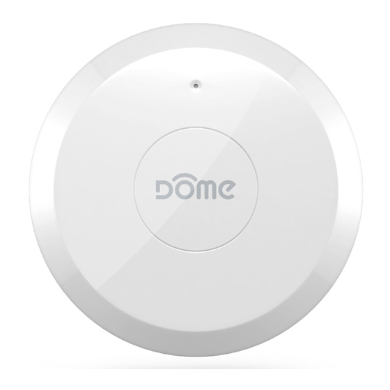
Description & Features The Dome Leak Sensor is a battery powered Z-Wave Plus device that can detect wetness and send a notification when it does so. The Leak Sensor consists of two parts—the “SENSOR ASSEMBLY,” and the optional “REMOTE SENSOR PROBE.”... -
Page 5: Specifications
Sensor The LED Indicator will flash once indicating factory reset. Only do Leak Sensor Note: Requires the DOME Hub or any other Z-Wave certified Hub this if the controller is disconnected or otherwise unreachable! Z-Wave Controller notifying Figure 4 - Using the Sensor... -
Page 6: Physical Characteristics
Physical Characteristics MAIN BODY COVER BATTERY TAB BATTERY MAIN BODY BASE MAIN BODY CRADLE REMOTE SENSOR PROBE Figure 1 - Exploded View nt Edition. INDICATOR LED Only. CONNECT BUTTON SCREW HOLE SolidWorks Student Edition. For Academic Use Only. METAL FEET SPEAKER METAL FEET Figure 2 - Showing individual parts A. -
Page 7: Inclusion & Exclusion
Inclusion & Exclusion Inclusion Follow the instructions for your Z-Wave Certified Conto enter inclusion mode. When prompted by the controller: 1. The Leak Sensor should be within 10’ of your Z-Wave controller for the inclu- sion process. After successful pairing, the device can be brought to the desired location. -
Page 8: Factory Reset & Misc. Functions
Factory Reset & Misc. Functions Resetting the Leak Sensor If needed, the Leak Sensor can be reset locally by following these steps. Only do this when your Z-Wave controller is disconnected or otherwise unreachable. Beware that resetting your device will disconnect it from the system: 1. -
Page 9: Physical Installation
Physical Installation The device should already be included in your Z-Wave system before continuing further. Study the Pre-Installation Checklist below for a broad overview of in- stallation options and other notes to bear in mind Pre-Installation Checklist 9 The MAIN BODY CRADLE and REMOTE SENSOR PROBE are optional, to help monitor hard-to-reach areas—study Figures 3 and 4 to understand when, where, and why to use the REMOTE SENSOR PROBE 9 The Leak Sensor detects moisture the moment water contacts the... - Page 10 Installation—Without the REMOTE SENSOR PROBE 1. Make sure the Leak Sensor is already included in your Z-Wave System and bring it to your desired installation location. 2. Confirm that your device can communicate with your Z-Wave Controller from the final installed location before proceeding. 3.
-
Page 11: Led Behavior
LED Behavior Color Behavior This happens when… Blink 5 times in 5 seconds …the Leak Sensor was just powered on, but is not (slow) yet included in a system. Blink 5 times in 2.5 …the CONNECT BUTTON is pressed 3 times quickly seconds (medium) (regardless of inclusion status.) Blink 5 times in 1.5... -
Page 12: Button Behavior
Button Behavior Action Condition Result Press and hold Device sends a wake up notification to its Leak Sensor Already CONNECT BUTTON controller, awaits further instructions, and blinks Included in System the LED Indicator once for 2 seconds Leak Sensor Already Device sends node info to Group 1 Included in System Leak Sensor Already... -
Page 13: Compatible Command Classes
Compatible Command Classes Notes Command Class Device Reset Locally V1 (0x5A) Powerlevel V1 (0x73) Battery V1(0x80) Association Group Information V1 (0x59) Returned Value: 01 06 00 0C 05 0C 05 Z-Wave Plus Version: 01 Role Type: 06 (Slave Sleeping Reporting) Z-Wave Plus Info V2 (0x5E) Node Type: 00 (Z-Wave Plus Node) - Page 14 Command Class Notes Group 1 Group 1 is the “Lifeline” group, which can hold five members, typically including the main Z-Wave controller. The Leak Sensor sends this group a Notification Report and a Binary Sensor Report when water is detected or removed.
-
Page 15: Configuration Parameters
Configuration Parameters Configuration parameters are sent using a standard syntax to ensure interopera- bility between all manufacturers’ products. All values are represented using the hexadecimal number system. Typical syntax is as shown below. Note that the value sent must be the exact size, in bytes, as accepted by the setting. -
Page 16: Configuration Parameters Cont'd
Configuration Parameters Cont’d When the Leak Sensor detects a leak, it beeps intermittently in the pattern shown in Figure 5. Total Alarm Duration, Mute Time, Initial Alarm, and Reminder Alarm duration times are all configurable using Configuration Parameters 1, 2, 3, and 4 respectively. Total Alarm Duration Initial Reminder... -
Page 17: Troubleshooting
To boost your Z-Wave network coverage, add a few non-battery powered Z-Wave devices between the controller and the furthest device, like the Dome On/Off Plug or Water Main Shut-Off. You can even purchase dedicated Z-Wave extenders from 3rd party manufacturers. -
Page 18: Warranty & Support
If you believe the product is defective, has a missing or broken 1153 Timber Dr., Elgin, IL 60123 part or are having difficulty with it please contact Dome as list- ed above for a quick and efficient solution to the problem.

Need help?
Do you have a question about the DMWS1 and is the answer not in the manual?
Questions and answers