
Related Manuals for Sony CCU-700A


Summary of Contents for Sony CCU-700A
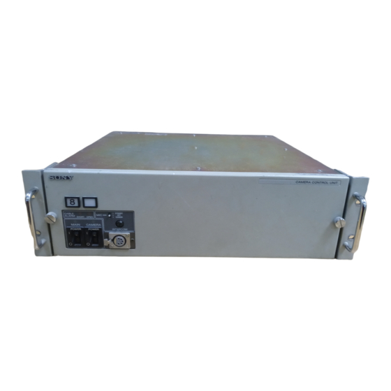
- Page 1 CAMERA CONTROL UNIT CCU-700A/700AP OPERATION MANUAL English 1st Edition (Revised 2) Serial No. 15001 and Higher (UC) Serial No. 45001 and Higher (CE) Serial No. 50001 and Higher...
- Page 2 For the customers in Europe WARNING WARNING To prevent fire or shock hazard, do not expose the unit This is a Class A product. In a domestic environment, to rain or moisture. this product may cause radio interference in which case the user may be required to take adequate measures.
-
Page 3: Table Of Contents
Table of Contents Overview .................... 2 Location and Function of Parts and Controls ........ 4 Front Panel ..................4 Rear Panel ..................5 Specifications ..................8 Manuals for the BVP-700-series video camera system characteristics of the device, such as features, Three types of manuals are provided for the functions of each part and specifications, are BVP-700-series video camera system: an... -
Page 4: Overview
500/550-series camera system, separate then supplies 240 volts of AC when a camera and components are used for signal processing and the CCU-700A/700AP are connected with a triax camera control. Signal control is performed with cable. The CCU-700A/700AP also has alarm... - Page 5 Rack-mountable Camera number output The CCU-700A/700AP is three units high and can The CCU-700A/700AP outputs the camera number be mounted in a 19-inch EIA standard rack. of the BVP-700/750/500/550-series connected to For details on rack mounting, refer to the System the CCU-700A/700AP through the INTERCOM Manual.
-
Page 6: Location And Function Of Parts And Controls
Lights when the unit receives a red tally signal. headset with a plug other than XLR 5-pin type, When the CALL button on the video camera, consult an authorized Sony representative. MSU-700 Master Setup Unit, or RCP-700-series Remote Control Panel is pressed, the lamp lights if 6 CAMERA POWER switch and indicator it is not lit, or goes dark if it is lit. -
Page 7: Rear Panel
Rear Panel ANALOG OUTPUT block ANALOG INPUT block R, G, and B connectors PROMPTER connectors Y, R–Y, and B–Y connectors REFERENCE connectors CHARACTER connector RET1 through RET4 connectors WF1 and WF2 connectors PIX1 and PIX2 connectors !¡ MIC OUTPUT connectors VBS1, VBS2, and VBS3 connectors !™... - Page 8 They function when an optional BKP-7312 SDI Connect to the sync signal input connector of a input board is installed in the CCU-700A/700AP, waveform monitor or picture monitor. and function as return video 1 and 2 input !£...
- Page 9 The operating voltage of the CCU-700AP is set to 220 to 240 V AC at the factory. If the voltage of your local power line is different, change the setting of the voltage selector. For changing the voltage selector setting, contact qualified Sony service personnel.
-
Page 10: Specifications
× 15 inches) 1.0 Vp-p, 75 ohms Mass Approx. 19 kg (41 lb 14 oz) WF 1 and WF 2 BNC type (2) CCU-700A: 0.714 Vp-p, Input connectors 75 ohms ANALOG INPUT CCU-700AP: 0.7 Vp-p, REFERENCE BNC type (1, with... - Page 11 Input and output connectors CAMERA Triax (1) CCU-700A: King type CCU-700AP: Fischer type COAX BNC type (1) RCP/CNU REMOTE 8-pin multiconnector (1) AUX REMOTE 8-pin multiconnector (1) INTERCOM/TALLY/PGM 19-pin multiconnector (1) TALLY: 24 V DC, TTL level, or contact selectable...
- Page 13 The material contained in this manual consists of information that is the property of Sony Corporation and is intended solely for use by the purchasers of the equipment described in this manual. Sony Corporation expressly prohibits the duplication of any...
- Page 14 Printed in Belgium Sony Corporation CCU-700A/700AP (UC/CE, 1999.12.08 1995 B & P Company 3-810-216-03 (2)
Need help?
Do you have a question about the CCU-700A and is the answer not in the manual?
Questions and answers