HP integrity superdome x Service Manual
Hide thumbs
Also See for integrity superdome x:
- Quickspecs (30 pages) ,
- Product end-of-life disassembly instructions (13 pages) ,
- Product end-of-life disassembly instructions (13 pages)
Table of Contents
Troubleshooting

Related Manuals for HP integrity superdome x


Summary of Contents for HP integrity superdome x
- Page 1 HPE Integrity Superdome X Service Guide for Users Abstract This guide describes the HPE Integrity Superdome X and provides user service information. Part Number: 794235-007 Published: November, 2016 Edition: 7...
-
Page 2: Table Of Contents
Acoustic noise specifications................... 29 Sample site inspection checklist for site preparation..............30 Updating firmware.................34 Prerequisites..........................34 Installing the latest complex firmware using HP SUM..............34 Manually updating the complex firmware..................34 Download firmware bundle....................35 Update the complex firmware..................35 I/O firmware and drivers....................36 SMH and WBEM providers.................... - Page 3 Partition Name..........................39 Partition Power Operations......................39 PARSTATUS..........................39 UUID for nPartitions........................40 nPartition states.......................... 40 nPartition runstate........................41 nPartition and resource health status..................41 Troubleshooting..................43 General troubleshooting methodology..................43 LED status information.....................43 OA access........................43 OA CLI..........................43 Gathering power related information................44 Gathering cooling related information................
- Page 4 Websites....................98 Support and other resources...............99 Accessing Hewlett Packard Enterprise Support................. 99 Accessing updates........................99 Customer self repair........................99 Remote support........................100 Warranty information.........................100 Regulatory information......................100 Documentation feedback......................101 Utilities....................102 UEFI............................102 UEFI Shell and POSSE commands..................102 Boot Maintenance Manager......................106 Onboard Administrator......................108 Connecting to the OA with a local PC..........109 Connecting a PC to the OA service port...................
-
Page 5: Revision History
© 2016 Hewlett Packard Enterprise Development LP Notices The information contained herein is subject to change without notice. The only warranties for Hewlett Packard Enterprise products and services are set forth in the express warranty statements accompanying such products and services. Nothing herein should be construed as constituting an additional warranty. Hewlett Packard Enterprise shall not be liable for technical or editorial errors or omissions contained herein. - Page 6 Notices Notices The information contained herein is subject to change without notice. The only warranties for Hewlett Packard Enterprise products and services are set forth in the express warranty statements accompanying such products and services. Nothing herein should be construed as constituting an additional warranty. Hewlett Packard Enterprise shall not be liable for technical or editorial errors or omissions contained herein.
-
Page 7: New And Changed Information
New and changed information • 794235–007 edition ◦ Updated OS support list ◦ Added links to current OS and spare parts information • 794235–006 edition ◦ Updated access to OS white papers for firmware updates ◦ Updated Insight Display screenshots ◦... -
Page 8: Hpe Integrity Superdome X Overview
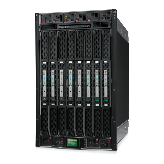
Superdome X servers. Complex components Integrity Superdome X consists of a single compute enclosure containing one to eight BL920s Gen8 or Gen9 blades. It also includes interconnect modules, manageability modules, fans, power supplies, and an integrated LCD Insight Display. The Insight Display can be used for basic enclosure maintenance and displays the overall enclosure health. -
Page 9: Manageability Subsystem
Server blades and partitions Integrity Superdome X supports multiple nPartitions of 2, 4, 6, 8, 12, or 16 sockets (1, 2, 3, 4, 6, or 8 blades). Each nPartition must include blades of the same type but the system can include nPartitions with different blade types. -
Page 10: Compute Enclosure Overview
Infiniband HPE IB FDR 2P 545M (BL920s Gen9) Not all types of cards are supported on Gen8 and Gen9 blades. For a complete list of supported I/O cards and firmware requirements, see the Firmware Matrix for HPE Integrity Superdome X servers at http:// www.hpe.com/info/superdomeX-firmware-matrix. - Page 11 Item Description Power supply bay 7 Power supply bay 8 Power supply bay 9 Power supply bay 10 Power supply bay 11 Power supply bay 12 Table Continued HPE Integrity Superdome X overview...
- Page 12 Air intake slot (Do not block) Power supply bay 6 Power supply bay 5 Insight Display Power supply bay 4 Power supply bay 3 Power supply bay 2 Power supply bay 1 Blade slots Air intake slot (Do not block) HPE Integrity Superdome X overview...
- Page 13 Power supply bay numbering HPE Integrity Superdome X overview...
- Page 14 Server blade slot numbering HPE Integrity Superdome X overview...
- Page 15 OK button Accepts the highlighted selection and navigates to the selected menu Down arrow button Moves the menu selection down one position Up arrow button Moves up the menu selection one position HPE Integrity Superdome X overview...
- Page 16 Compute enclosure rear components Item Description AC power connectors (upper) Fan bay 1 Fan bay 6 Fan bay 2 Fan bay 7 Fan bay 3 Table Continued HPE Integrity Superdome X overview...
- Page 17 OA bay 2 Power supply exhaust vent (Do not block) AC power connectors (lower) Fan bay 15 Fan bay 14 Fan bay 13 Fan bay 12 Fan bay 11 OA bay 1 Interconnect bay 7 Table Continued HPE Integrity Superdome X overview...
- Page 18 Fan bay numbering Interconnect bay numbering Each Integrity Superdome X enclosure requires interconnect modules to provide network access for data transfer. Interconnect modules reside in bays located in the rear of the enclosure. Review blade slot numbering to determine which external network connections on the interconnect modules are active.
- Page 19 Interconnect bay label interconnect bay FlexLOM 1 port 1 FlexLOM 1 port 2 FlexLOM 2 port 1 FlexLOM 2 port 2 Mezzanine 1 port 1 Mezzanine 1 port 2 Mezzanine 1 port 3 Table Continued HPE Integrity Superdome X overview...
-
Page 20: Server Blade Overview
Mezzanine 3 port 4 NOTE: For information on the location of LEDs and ports on individual interconnect modules, see the documentation that ships with the interconnect module. More information • Integrity Superdome X QuickSpecs Server blade overview Product Processors DIMM slots Supported... - Page 21 Mezzanine connector 1 Type A Mezzanine connector 2 Type A/B FlexLOM slot 2 CPU 0 Mezzanine connector 3 Type A/B FlexLOM slot 1 DDR3 DIMM slots (48) — BL920s Gen8 DDR4 DIMM slots (48) — BL920s Gen9 SUV board HPE Integrity Superdome X overview...
- Page 22 IMPORTANT: The SUV port does not provide console access and the serial port is unused. Item Description Server blade connector Serial USB ports (2) Video More information Integrity Superdome X QuickSpecs HPE Integrity Superdome X overview...
-
Page 23: System Specifications
System specifications Dimensions and weights Component dimensions Table 1: Component dimensions Component Width Depth Height Compute enclosure 44.7 cm 82.8 cm 79.8 cm 17.6 in 32.6 in 31.4 in Server blade 5.13 cm 52.25 cm 62.18 cm 2.02 in 20.60 in 24.48 in Component weights Table 2: Compute enclosure weights... -
Page 24: Rack Specifications
Component Weight Max. quantity per enclosure GPSM 1.2 kg 2.6 lb 3.3 kg 7.3 lb I/O interconnect module 1.3 kg 2.9 lb Server blade 12-16 kg 26-35 lb Does not include I/O chassis or Midplane Brick. Part of the enclosure assembly that the XFM and I/O switch modules install into Maximum weight for an interconnect module. -
Page 25: Internal And External Site Door Requirements
Internal and external site door requirements Internal site doorways must obey the following height requirements: • For the 642 1075 mm rack — no less than 200.19 cm (78.816 in) • For the 642 1200 mm rack — no less than 200.66 cm (79.00 in) To account for the lifted height of the pallet, external doorways must obey the following height requirements: •... - Page 26 Table 6: Enclosure single-phase HPE 2400 W power supply specifications Specification Value Power cord IEC-320 C19-C20 Output 2450 W per power supply Input requirements Rated input voltage 200–240 VAC Rated input frequency 50-60 Hz Rated input current per power supply (maximum) 13.8 A at 200 VAC 13.3 A at 208 VAC 12.6 A at 220 VAC...
- Page 27 Table 8: Enclosure 3-phase 2400 W power supply specifications (International) Specification Value Power cords (4) IEC-309 220–240 VAC, 5-pin, 16 A 3.0 m (10 ft) Max input current per line cord 12.1 A at 220 VAC 11.1 A at 240 VAC Output 2450 W per power supply Input requirements...
-
Page 28: Environmental Specifications
More information Generic Site Preparation Guide Environmental specifications Temperature and humidity specifications The following table contains the allowed and recommended temperature and humidity limits for both operating and nonoperating Integrity Superdome X systems. Specification Value Temperature range Allowable Operating Range +5°... -
Page 29: Cooling Requirements
Generic Site Preparation Guide Cooling requirements Integrity Superdome X is a rack-mounted system that cools by drawing air in the front and exhausting it out the rear. General ASHRAE best practices must be followed when installing the system in a data center. -
Page 30: Sample Site Inspection Checklist For Site Preparation
Sample site inspection checklist for site preparation See Customer and Hewlett Packard Enterprise Information and Site inspection checklist. You can use these tables to measure your progress. Table 11: Customer and Hewlett Packard Enterprise Information Customer Information Name: Phone number: Street address: City or Town: State or province:... - Page 31 Check either Yes or No. If No, include comment or date. Computer Room Number Area or condition Comment or Date Is a raised floor installed and in good condition? What is the floor to ceiling height? [228 cm (7.5 ft) minimum] Is the raised floor adequate for equipment loading? Are channels or cutouts available for cable routing?
- Page 32 Check either Yes or No. If No, include comment or date. Computer Room Number Area or condition Comment or Date Are the input circuit breakers adequate for equipment loads? Safety Is an emergency power shutoff switch available? Is a telephone available for emergency purposes? Does the computer room have a fire protection system? Does the computer room have anti-static flooring installed?
- Page 33 Check either Yes or No. If No, include comment or date. Computer Room Number Area or condition Comment or Date Can temperature changes be held to 5° C (9° F) per hour with tape media? Can temperature changes be held to 20°...
-
Page 34: Updating Firmware
It has an integrated hardware discovery engine that discovers the installed hardware and the current versions of firmware in use on target servers. HP SUM also has logic to install updates in the correct order and ensure all dependencies are met before deployment of a firmware update. It also contains logic to prevent version-based dependencies from destroying an installation and ensures updates are handled in a manner that reduces any downtime required for the update process. -
Page 35: Download Firmware Bundle
Download firmware bundle Hewlett Packard Enterprise recommends running only approved firmware versions. For the latest approved firmware versions, see the Firmware Matrix for HPE Integrity Superdome X servers at http:// www.hpe.com/info/superdomeX-firmware-matrix. Follow the instructions provided in the bundle Release Notes. -
Page 36: I/O Firmware And Drivers
NOTE: You must install the SMH package before the WBEM providers or in the same session. Use the information provided in the Firmware Matrix for HPE Integrity Superdome X servers document to download the correct WBEM providers. Reboot is not required for SMH and WBEM providers changes to take effect. -
Page 37: Running Oss On Integrity Superdome X Systems
SLES 12 SP1 (BL920s, all versions) ◦ SLES 12 SP2 (BL920s, all versions) For the latest list of supported OSs, see the Firmware Matrix for HPE Integrity Superdome X servers at http://www.hpe.com/info/superdomeX-firmware-matrix. Using Microsoft Windows Server For detailed information about using the Windows OS on Integrity Superdome X systems, see the Running Microsoft Windows Server on HPE Integrity Superdome X white paper at http://www.hpe.com/... -
Page 38: Using Vmware
VMware vSphere on HPE Integrity Superdome X white paper at http://www.hpe.com/support/ superdomeXvmware-whitepaper. Using Red Hat Linux For detailed information about using RHEL on Integrity Superdome X systems, see the Running Linux on HPE Integrity Superdome X white paper at http://www.hpe.com/support/superdomeXlinux- whitepaper. -
Page 39: Partitioning
Partitioning This chapter provides information on partition identification and operations. Partition Identification Every partition has two identifiers: a partition number (the primary identifier from an internal perspective) and a partition name (a more meaningful handle for administrators). Partition Number • A numeric value that is well suited for programmatic use and required by the hardware for configuring routing, firewalls, etc. -
Page 40: Uuid For Npartitions
“Partition commands” in the HPE Integrity Superdome X and Superdome 2 Onboard Administrator Command Line Interface User Guide. UUID for nPartitions The partition firmware subsystem will generate an unique nPar UUID when a user creates an nPartition. The UUID will be communicated to system firmware, which places the UUID on the SMBIOS for the OS and the management applications to pick up and use this as “Universally Unique Identifiers”... -
Page 41: Npartition Runstate
Unknown/DETACHED 0.0/8192.0 nPar0001 D-Degraded ** Actual allocated for Active and User requested for Inactive partitions To list all the nPartitions and their boot states and runstates (active or inactive states), use the parstatus -P command on the OA CLI. parstatus -P [Partition] Par State/RunState Status* # of... - Page 42 Resource Usage Description Empty The slot has no resource. Inactive Resource is inactive. Unintegrated Firmware is in the process of discovering or integrating the resource. It cannot be used for partition operations. Active The resource is active in the partition. The partition resources might display one of the following health status: Resource Meaning...
-
Page 43: Troubleshooting
See the HPE Integrity Superdome X and Superdome 2 Onboard Administrator User Guide and the HPE Integrity Superdome X and Superdome 2 Onboard Administrator Command Line Interface User Guide for additional information on troubleshooting using the OA. -
Page 44: Gathering Power Related Information
Hewlett Packard Enterprise recommends checking the system status information using show complex status before continuing with troubleshooting: sd-oa1> show complex status Status: OK Enclosure ID: OK Enclosure: OK Robust Store: OK CAMNET: OK Product ID: OK Xfabric: OK Diagnostic Status: Thermal Danger Cooling Device Failure... - Page 45 Fan 5: 10759 RPM (60%) Fan 6: 8600 RPM (48%) Fan 7: 8600 RPM (48%) Fan 8: 8600 RPM (48%) Fan 9: 8599 RPM (48%) Fan 10: 8599 RPM (48%) Fan 11: 8602 RPM (48%) Fan 12: 8601 RPM (48%) Fan 13: 8600 RPM (48%) Fan 14:...
-
Page 46: Gathering Cooling Related Information
Link 3: Dormant Link 4: Dormant sd-oa1> show blade status all Blade #1 Status: Power: On Current Wattage used: 1325 Watts Health: OK Unit Identification LED: Off Diagnostic Status: Internal Data Management Processor OK Thermal Warning Thermal Danger I/O Configuration Power OK <<<... - Page 47 Device Failure Device Degraded Missing Device Indicted • show blade status all sd-oa1> show blade status all Blade #1 Status: Power: On Current Wattage used: 1100 Watts Health: OK Unit Identification LED: Off Virtual Fan: 36% Diagnostic Status: Internal Data Management Processor OK Thermal Warning Thermal Danger...
-
Page 48: Gathering Failure Information
Thermal Danger OK <<<< I/O Configuration Power Device Failure Device Degraded Gathering failure information To obtain information about failures recorded by the system, use the following commands: • Show cae –L sd-oa1> show cae -L Sl.No Severity EventId EventCategory PartitionId EventTime Summary ###########################################################################... -
Page 49: Recommended Troubleshooting Methodology
Probable Cause 1 : Data center air conditioning is not functioning properly Recommended Action 1 : Fix the air conditioning problem Probable Cause 2 : The system air intake is blocked Recommended Action 2 : Check and unblock air intakes Replaceable Unit(s) : Part Manufacturer : HPE Spare Part No. -
Page 50: Developer Log Collection
NOTE: The COPY command also supports additional protocols: TFTP, HTTP, HTTPS, SCP, and SFTP. For more information about the COPY command, see the HPE Integrity Superdome X and Superdome 2 Onboard Administrator Command Line Interface User Guide. 4. CLEAR ARCHIVE... -
Page 51: Troubleshooting Tables
zany-oa> SHOW ARCHIVE Debug Logs Time _______________________________________________ ____________________ archive://CH-zany-oa-20140529_1555–logs.tar.gz May 29, 2014 15:55 zany-oa> COPY archive://CH-zany-oa-20140529_1555–logs.tar.gz USB/dec/CH-zany-oa-20140529_1555–logs.tar.gz The file archive://CH-zany-oa-20140529_1555–logs.tar.gz was successfully copied to usb://d2/dec/CH-zany-oa-20140529_1555–logs.tar.gz. Generating a debug archive Use this procedure to generate a new debug archive, and then copy to a USB thumb drive or FTP site. 1. - Page 52 Table 14: Basic troubleshooting Step Condition Action Server blade appears non- Nothing is logged for this condition. functional – no front panel 1. For new blade installations, review the installation LEDs are on and no fans are procedures. running. OA CLI is running. 2.
- Page 53 Step Condition Action Cannot see UEFI prompt on Nothing can be logged for this condition. system console. UEFI is 1. If the blade was able to join the partition but didn't reach running. the UEFI prompt, then the issue might be I/O related. Check the CAE for any issues with PCIe card drivers.
- Page 54 Table 15: Advanced troubleshooting Step Symptom/condition Action Cannot read SEL. SEL logging has stopped (health is steady green and power is steady green). 1. Examine console messages for any UEFI errors or warnings about operation or communications. 2. Ensure that the Robust Store is functioning properly. Try to read the FPL.
-
Page 55: Troubleshooting Tools
Step Symptom/condition Action MCA occurs during partition Front panel LEDs indicate that the server blade detected a operation; server blade Critical (catastrophic or viral) bus error. reboot of OS is prevented. System firmware is running to gather and log all error data for this MCA event. - Page 56 Item Name Description Power icon Indicates if the server blade is powered on and active. Green = Powered on; active Flashing amber = Powered on; not active Off = No power supplied to the server blade UID icon Blue = UID on NIC icon 1 Indicates the status of the NIC.
- Page 57 Power supply LEDs NOTE: The power supplies at the top of the enclosure are upside down. Power LED 1 (green) Fault LED 2 (amber) Condition No AC power to the power supply Normal Power supply failure Fan LED Troubleshooting...
- Page 58 Green = On XFM crossbar fabric port 1 Link Cable Status LED 1 N/A for Integrity Superdome X XFM crossbar fabric port 2 Link Cable Status LED 2 N/A for Integrity Superdome X XFM crossbar fabric port 3...
- Page 59 Item Name Description XFM crossbar fabric port 7 Link Cable Status LED 7 N/A for Integrity Superdome X XFM crossbar fabric port 8 Link Cable Status LED 8 N/A for Integrity Superdome X Health LED Flashing yellow = Degraded; indicted...
- Page 60 Off = OK Flashing red = Deconfigured GPSM LEDs and components Item Name Description Door display power Unused for Integrity Superdome X systems connector UID LED Blue = UID on Health LED Flashing yellow = Degraded; indicted Off = OK...
- Page 61 Item Name Description Local Clock Distribution Indicates the status of the global clock signal distributed to blades in the compute enclosure. Green = OK Flashing yellow = Critical error External Clock Input LED Indicates the status of the global clock signal distributed to connected enclosures.
- Page 62 Item Name Description Reset button For the different uses of this button, see the HPE Integrity Superdome X and Superdome 2 Onboard Administrator User Guide. OA management LAN port Standard CAT5e (RJ-45) Ethernet port (100/1000Mb) which provides access to the management subsystem. Access to the OA's CLI and GUI interfaces, interconnect modules, and iLO features, such as Virtual Media, requires connection to this port.
-
Page 63: Oa Gui
OA GUI The OA GUI provides partition status and FRU information. For more information on using the OA GUI, see the HPE Integrity Superdome X and Superdome 2 Onboard Administrator User Guide. NOTE: CAE events and errdump information is not available using the GUI. You must use the command line for this information. -
Page 64: Acquitting Indictments
Deconfiguration is the act of disabling a component in the system. This happens when analysis finds that a component has a serious fault. A components deconfiguration status is composed of the following parts: • requested state—What the user or Analysis Engine would like to have the component set to. •... -
Page 65: Viewing Deconfigured Components
FRU Type: Blade DIMM Location: 0x0100FF0101180B74 enclosure1/blade1/cpusocket1/dimm18 Timestamp: Wed Oct 29 09:11:12 2014 Indictment State: Indicted Requested Deconfig State: Configured Current Deconfig State: Configured dimm-1/1/1/18 Location: 18B Status: OK No Errors Logged. Viewing deconfigured components The show deconfig command will list all components in the complex which are deconfigured or have a pending request to be deconfigured. -
Page 66: Viewing Indictment Acquittals
Additional DIMMs that are deconfigured without being indicted are not faulty components and should not be replaced. Viewing indictment acquittals The show acquit command will list all components in the complex which have had indictments acquitted. The output includes the type, physical location, indication of the cause for indictment, and timestamp. - Page 67 Location: 0x0100FF0100060A74 enclosure1/blade1/cpusocket0/ dimm6 Timestamp: Mon Mar 17 07:42:28 2014 Indictment State: Indicted Requested Deconfig State: Deconfigured Current Deconfig State: Deconfigured dimm-1/1/0/6 Location: 6A Status: OK No Errors Logged. --- Install History 1 --- Discovery: Indictment Timestamp: Mon Mar 17 04:42:18 2014 (Detailed info about the FRU is provided here if it exists.
-
Page 68: Subcomponent Isolation And Deconfiguration Displays
Alert ID: 2700420140317044214 Serial Num: 1X123456 Product Name: DDR3 DIMM - Indicted / Acquitted - Type Timestamp Entity Reason Ind Mon Mar 17 04:42:10 2014 See reason above. Acq Mon Mar 17 07:02:28 2014 User User request. - SubFru Isolation - Entire FRU indicted. - Page 69 COMPONENT: Fault NOTE: For Integrity Superdome X, there are FlexLOMs instead of LOMs. Each FlexLOM has its own physical location. Therefore, indictments against FlexLOMs are issued against the FlexLOM physical location, rather than indicting the blade and setting one of the LOM bits. The blade SubFru isolation display will continue to show LOM bits, but these should always have a value of 0.
- Page 70 Entity name: Fault [Only the flagged entity is listed.] Where Entity name is one of the following: XNC is flagged WJ Port n Entire port is flagged WJ Port n Link Upper Half (Upper port flagged) WJ Port n Link Lower Half (Lower port flagged) QPI Link n Entire link is flagged QPI Link n Reduced Width...
- Page 71 The OA CLI SHOW CAE command can identify specific VRDs associated with these faults. See Core Analysis Engine on page 79 for more information. The SubFRU deconfiguration display section has the same layout as the SubFru Isolation display. CPU socket subcomponent displays There are three different sets of CPU subcomponent data, contained in three different displays.
-
Page 72: Using Event Logs
GPSM subcomponent displays - SubFru Isolation - - GPSM - - CAMNet Ports - 1 - 2 - 3 - 4 - 5 - 6 - 7 - 8 SW Port: Blade: XFM: Other GSPM: FPGA: OA subcomponent display - SubFru Isolation - - OA - - CAMNet Ports - -A- -B-... -
Page 73: Live Viewer
The OA can timestamp and filter events, then store and transfer them to event log readers. Log entries can be read by management applications in the following: • • • SEL viewers • FPL viewers • Live Event viewers • Log entries can be cleared by OS management applications or by the OA itself. - Page 74 NOTE: The option C can be used to display column header information at any point of time while in the Live viewer. The column header corresponding to the event viewer format currently active will be displayed. Welcome to the Live Event Viewer WARNING: Due to connection speed and/or to the number of events being generated and/or to the format...
-
Page 75: Sel And Fpl Viewers
BOOT_LOAD_FW_ADDR 1,1,0,0,0 0 0900232401e10000 652e6c7049657844 BOOT_LOAD_FW_MODULE PDHC 1 36801df200e10000 0000000000000000 ELS_START_PARTITION 03/17/2014 14:26:50 None 0 168024b600e10000 0000000000000000 ELS_OA_SAVE_RECOV_FILE 03/17/2014 14:26:50 SEL and FPL viewers Both the SEL and FPL viewers provide a way for OA users to view stored event records. The OA supports multiple simultaneous viewers. - Page 76 Welcome to the Forward Progress Log (FPL) Viewer The following FPL navigation commands are available: D: Dump log starting at current block for capture and analysis F: Display first (oldest) block L: Display last (newest) block J: Jump to specified entry and display previous block +: Display next (forward in time) block -: Display previous (backward in time) block <cr>: Repeat previous +/- command...
- Page 77 IO_PROCESS_OPTION_ROM 5512562 SFW 1,1,0,0,0 0 0100232501e10000 00000000783d0000 BOOT_LOAD_FW_ADDR 5512561 SFW 1,1,0,0,0 0 16002ad601e10000 0000000010000000 BOOT_LOAD_FW_ADDR_PREF 5512560 SFW 1,1,0,0,0 0 160024d301e10000 0000010100000000 IO_PROCESS_OPTION_ROM 5512559 SFW 1,1,0,0,0 0 16002af201e10000 00000000004900a9 IO_UEFI_DRIVER_VERSION 5512558 SFW 1,1,0,0,0 0 0100232501e10000 0000000078436000 BOOT_LOAD_FW_ADDR 5512557 SFW 1,1,0,0,0 0 16002ad601e10000 0000000010000000 BOOT_LOAD_FW_ADDR_PREF 5512556 SFW 1,1,0,0,0...
- Page 78 The following alert threshold options are available: Alert thresholds will cause events at the selected threshold and below to be shown 2: Informational 3: Warning 5: Critical 7: Fatal The following event filter options are available: B: Blade P: Partition V: Virtual Partition U: Unfiltered Current alert threshold: Alert threshold 2...
-
Page 79: Core Analysis Engine
62375 PDHC 2 4480223820e17821 0100ff03ffffff94 DIMM_LOADING_ORDER_DONE 62375 03/17/2014 13:40:58 62374 None 2 43801fa300e1781f 413000000000101f CAE_FRU_INDICTMENT 62374 03/17/2014 13:40:54 Core Analysis Engine The CAE is a diagnostic tool that analyzes system errors and generates events that provide detailed descriptions of severity, probable cause, recommended action, replaceable units, and more. It also initiates self healing corrective actions. - Page 80 (-L) [(-b)] : Display archived events (-E) [(-b)] (-n) <Sl.No> : Display archived event details with serial number equal to <Sl.No> [-h] : Display usage of this command To view the list of events generated and analyzed, run the following: OA-CLI>...
- Page 81 Error Log Data : Error Log Bundle : 400000000001e86c See the HPE Integrity Superdome X and Superdome 2 Onboard Administrator Command Line Interface Guide for the correct and detailed command syntax. The HR Viewer can also provide help in visualizing component issues.
- Page 82 The OA provides diagnostic and configuration capabilities. See the HPE Integrity Superdome X and Superdome 2 Onboard Administrator Command Line Interface Guide for more information on the OA CLI commands. You can access the OA CLI through the network. The status logs consist of the following: •...
-
Page 83: Troubleshooting Processors
Locally accessing the OA If needed for debugging purposes, the OA can be accessed locally through a serial port connector on the rear of the OA module. Use a laptop or another computer as a serial console to communicate with the NOTE: Use of this interface is only for OA debugging purposes and to reset the OA password. -
Page 84: Troubleshooting Memory
Troubleshooting memory Symptom Memory errors can be separated into two categories depending on where they originate: • CPU to memory buffer errors — outlined in yellow below • Memory buffer to DIMM errors — outlined in green below Solution 1 Cause CPU to memory buffer errors The link between the CPU and the memory buffer is the SMI2 or VMSE link. - Page 85 The channel between the memory buffer and the DIMM is the DDR channel. Because up to three DIMMs reside on the same DDR channel and two DDR channels might be configured in lockstep (RAS mode enabled), up to six DIMMs are affected by a single faulty DIMM. It is important to distinguish faulty or suspect DIMMs from healthy DIMMs that happen to reside on the same bus.
-
Page 86: Troubleshooting Cards And Drivers
Cause Loss of enclosure settings The OA battery preserves the Integrity Superdome X enclosure settings, such as users and network settings. When the battery is low, there is a risk of looking these enclosure settings if the OA is removed or if AC power is interrupted. -
Page 87: Troubleshooting Firmware
Interconnect module firmware All firmware systems can be updated. System firmware recipe can be updated using HP SUM or manually using OA CLI. There are different bundles for each method. For instructions to update firmware and drivers, see Manually updating the complex firmware on page 34 and Installing the latest complex firmware using HP SUM on page 34. -
Page 88: Verifying And Installing The Latest Firmware Version
Verifying and installing the latest firmware version Hewlett Packard Enterprise recommends that all firmware on all devices be updated to the latest version after hardware installation is complete. Hewlett Packard Enterprise also encourages you to check back often for any updates that might have been posted. The most recent versions of software drivers and firmware are available on the support page. - Page 89 IMPORTANT: Check for indicts before and after each firmware update. Process Blade – Requires a nPar outage 1. Power OFF the partition the blade is assigned to. (See Note below this table) 2. Remove/Replace the suspect blade following the instructions in the service guide. 3.
-
Page 90: I/O Firmware
Process OA — No outage required 1. Ensure the suspect OA is the standby OA; use the force takeover command if needed. 2. Remove and replace the suspect OA. 3. Use the update firmware <uri> all command, pointing it to the <uri> of a bundle file that matches what is currently installed on the complex. -
Page 91: Interconnect Module Firmware
Card Gen8 minimum firmware Gen9 minimum firmware version version HPE Ethernet 10Gb 2-port Boot: 3.0.24 Boot: 2.3.45 560FLB / 560M Adapter UEFI: 4.5.19 UEFI: 4.9.10 HPE QMH2672 16Gb 2P FC Multiboot: 2.02.47 & 4.0.0.0–1 Multiboot: 2.02.47 & 4.0.0.0–1 FW: 7.04.00 FW: 7.04.00 BIOS: 3.28 BIOS: 3.31... -
Page 92: Troubleshooting Partitions
NOTE: All partition-related messages in OA syslog contain the string parcon:. See the HPE Integrity Superdome X and Superdome 2 Onboard Administrator Command Line Interface User Guide for information on uploading and downloading partition specification files and runtime Troubleshooting partitions... -
Page 93: Troubleshooting The Network
configuration files. These actions are not typically needed, but it is recommended to keep a valid copy of the configuration available for disaster recovery. Troubleshooting the network Cause An incorrect setup for the compute enclosure and complex wide internal network can lead to issues with the following tasks: •... -
Page 94: Troubleshooting Fabric Issues
Enclosure IP Mode: Disabled Troubleshooting fabric issues Cause The Integrity Superdome X has fabric connections between all the blades installed in the compute enclosure. Test fabric To determine the healthy status for all crossbar connections, use the HR> test fabric command. This is a valuable test during installation when all partitions can be taken down at the same time. -
Page 95: Troubleshooting Clock-Related Issues
GPSM Int Clk Ext Clk ========== ========== ========== GPSM 1/1 * ---- GPSM 1/2 * ---- SUCCESS: Clocks test passed. Clocks test complete. Success: Fabric, CAMNet, and Global Clock tests completed with no errors Show complex status Use this procedure to test for fabric issues when some or all partitions can’t be taken down at the same time. -
Page 96: Troubleshooting Mcas
Troubleshooting MCAs Cause In general, MCAs are partition-based crashes and are detected and reported by CAE. To obtain a general overview about an MCA event, run show CAE –L, and then use the command show CAE –E –n <ID> to obtain more details for the CAE event. To view problem action statements about the MCA event, use the show cae —L —c 10 command and note the Sl.No. -
Page 97: Troubleshooting The Blade Interface (System Console)
(bent pins, cracked traces, contamination or corrosion) on the FRU connection points and ensure proper mating/ seating occurs. If the problem persists, replace only one FRU at a time in the order given below. Test the system between each FRU replacement. Replaceable Units(s) : MCA data is also stored at the OA and can be retrieved by running the OA command show errdump dir mca as follows:... -
Page 98: Websites
Websites General websites Hewlett Packard Enterprise Information Library www.hpe.com/info/EIL Single Point of Connectivity Knowledge (SPOCK) Storage www.hpe.com/storage/spock compatibility matrix Storage white papers and analyst reports www.hpe.com/storage/whitepapers For additional websites, see Support and other resources. Websites... -
Page 99: Support And Other Resources
IMPORTANT: Access to some updates might require product entitlement when accessed through the Hewlett Packard Enterprise Support Center. You must have an HP Passport set up with relevant entitlements. Customer self repair Hewlett Packard Enterprise customer self repair (CSR) programs allow you to repair your product. If a... -
Page 100: Remote Support
convenience. Some parts do not qualify for CSR. Your Hewlett Packard Enterprise authorized service provider will determine whether a repair can be accomplished by CSR. For more information about CSR, contact your local service provider or go to the CSR website: http://www.hpe.com/support/selfrepair Remote support Remote support is available with supported devices as part of your warranty or contractual support... -
Page 101: Documentation Feedback
Additional regulatory information Hewlett Packard Enterprise is committed to providing our customers with information about the chemical substances in our products as needed to comply with legal requirements such as REACH (Regulation EC No 1907/2006 of the European Parliament and the Council). A chemical information report for this product can be found at: www.hpe.com/info/reach For Hewlett Packard Enterprise product environmental and safety information and compliance data,... -
Page 102: Utilities
Utilities UEFI UEFI is an OS and platform-independent boot and preboot interface. UEFI resides between the OS and platform firmware, allowing the OS to boot without having details about the underlying hardware and firmware. UEFI supports boot devices, uses a flat memory model, and hides platform and firmware details from the OS. - Page 103 UEFI Shell command Definition Displays or changes the current directory Clears standard output and optionally changes background color comp Compares the contents of two files connect Connects one or more UEFI drivers to a device Copies one or more files or directories to another location date Displays or changes the current system date dblk...
- Page 104 UEFI Shell command Definition exit Exits the UEFI Shell environment Executes commands for each item in a set of items Performs FTP operation getmtc Gets the MTC from BootServices and displays it goto Forces batch file execution to jump to specified location help Displays the UEFI Shell command list or verbose command help hexedit...
- Page 105 UEFI Shell command Definition parse Retrieves a value from a record output in a standard format pause Prints a message and waits for keyboard input Displays PCI device list or PCI function configuration space ping Pings a target machine using the UEFI IPv4 network stack ping6 Pings a target machine using the UEFI IPv6 network stack reconnect...
-
Page 106: Boot Maintenance Manager
UEFI Shell command Definition Displays or changes a file system volume label xchar Turns on/off extended character features Boot Maintenance Manager This menu allows you to change various boot options. The Boot Maintenance Manager contains the following submenus: • Boot Options Menu •... - Page 107 Boot Options The Boot Options menu contains the following options: • Add Boot Option • Delete Boot Option • Change Boot Order Driver Options The Driver Options menu contains the following options: Utilities...
-
Page 108: Onboard Administrator
Access to the OA can be restricted by user accounts. User accounts are password protected and provide a specific level of access to the server (not OS) and OA CLI commands. For more information on the OA, see the HPE Integrity Superdome X and Superdome 2 Onboard Administrator User Guide. -
Page 109: Connecting To The Oa With A Local Pc
3. Log into the OA with the "Administrator" user account and the OA default password located on the OA toe tag. For information on using the OA CLI, see the HPE Integrity Superdome X and Superdome 2 Onboard Administrator Command Line Interface User Guide. -
Page 110: Connecting A Pc To The Oa Serial Port
The service port connection is intended only as a temporary Ethernet connection to the enclosure private network to eliminate disconnecting the management port from the external management network for access to the OA during a maintenance event. Connecting a PC to the OA serial port If needed for debugging purposes, the OA can be accessed locally through a serial (debug) port connector on the rear of the OA module. -
Page 111: Modifying The Serial Connection Baud Rate
3. Log into the OA with the "Administrator" user account and the OA default password located on the OA toe tag. For information on using the OA CLI, see the HPE Integrity Superdome X and Superdome 2 Onboard Administrator Command Line Interface User Guide. -
Page 112: Insight Display
Insight Display NOTE: Images in this section might not accurately reflect Integrity Superdome X displays. Insight Display overview The Insight Display enables the rack technician to initially configure the enclosure. It also provides information about the health and operation of the enclosure. The color of the Insight Display varies with the condition of the enclosure health. -
Page 113: Health Summary Screen
The Main Menu of the Insight Display has the following menu options: • Health Summary • Enclosure Settings • Enclosure Info • Blade or Port Info • Turn Enclosure UID on/off • View User Note • Chat Mode If the active OA detects a USB key drive with any *.ROM , *.CFG or *.ISO files, a USB menu item appears at the bottom of the Main Menu. -
Page 114: Enclosure Settings Screen
When an error or alert condition is detected, the Health Summary screen displays the total number of error conditions and the error locations. Select Next Alert from the navigation bar, and then press the OK button to view each individual error condition. -
Page 115: Enclosure Info Screen
Active OA Service IP address • Current health status of the enclosure • Current enclosure ambient temperature • Current AC input power to the enclosure • Enclosure number • Enclosure name • Enclosure serial number (Integrity Superdome X) • Rack name Enclosure Info screen... -
Page 116: Blade And Port Info Screen
Blade and Port Info screen The Blade and Port Info screen displays information about a specific server blade. On the first screen, select the server blade number, and then press the OK button. Select Blade Info or Port Info, and press the OK button. -
Page 117: Turn Enclosure Uid On/Off Screen
To view the ports used by a specific server blade, select Port Info and press the OK button. The following screen shows a server blade with four embedded NICs. The other interconnect bays are empty. The four embedded NICs are connected to particular port numbers on the interconnect modules. Turn Enclosure UID On/Off screen The Main Menu displays Turn Enclosure UID Off when the enclosure UID is active, and displays Turn Enclosure UID on when the enclosure UID is off. -
Page 118: View User Note Screen
Selecting Turn Enclosure UID Off from the main menu turns off the rear enclosure UID LED and changes the color of the Insight Display screen to the current alert condition. View User Note screen The View User Note screen displays six lines of text, each containing a maximum of 16 characters. Use this screen to display helpful information such as contact phone numbers. -
Page 119: Insight Display Errors
Insight Display errors The enclosure installation is successful when all errors are corrected. The errors in the following sections are specific to installation and initial configuration of the enclosure. The following types of errors can occur when installing and configuring the enclosure: •... -
Page 120: Location Errors
Location (installation) errors occur when the component is not installed in the appropriate bay. Location errors can occur on server blades, power supplies, and fans. Integrity Superdome X systems are configured such that these errors should not occur unless the components have been moved. - Page 121 Procedure 1. Use the arrow buttons to navigate to Fix This, and then press OK. 2. Review and complete the corrective action suggested by the Insight Display. In most cases, you must remove the failed component to clear the error. 3.
-
Page 122: Warranty And Regulatory Information
Warranty and regulatory information For important safety, environmental, and regulatory information, see Safety and Compliance Information for Server, Storage, Power, Networking, and Rack Products, available at www.hpe.com/support/Safety- Compliance-EnterpriseProducts. Warranty information HPE ProLiant and x86 Servers and Options www.hpe.com/support/ProLiantServers-Warranties HPE Enterprise Servers www.hpe.com/support/EnterpriseServers-Warranties HPE Storage Products www.hpe.com/support/Storage-Warranties... -
Page 123: Turkey Rohs Material Content Declaration
• Belarus: • Kazakhstan: Manufacturing date: The manufacturing date is defined by the serial number. CCSYWWZZZZ (serial number format for this product) Valid date formats include: • YWW, where Y indicates the year counting from within each new decade, with 2000 as the starting point;... -
Page 124: Standard Terms, Abbreviations, And Acronyms
Standard terms, abbreviations, and acronyms ACPI Advanced configuration and power interface. ASCII American standard code for information interchange. ASIC Application-specific integrated circuit. BBRAM Battery-backed RAM. BBWC Battery-backed write cache. Boot console handler. Blade Entitlement Number Core Analysis Engine CAMnet completer module. Customer engineer. - Page 125 Extensible firmware interface. See also: UEFI Electronic Industries Association. Event management service. Electrostatic discharge. Fibre channel. Forward progress log. Field replaceable unit. File Transfer Protocol. GPSM Global partition services module. Host bus adapter. Health Repository Integrity Data Collector. iLO 4 Integrated Lights-Out 4.
- Page 126 PCIe Peripheral component interconnect express. Point-of-load. POSSE Pre-OS system start-up environment. POST Power-on self-test. Intel QuickPath Interconnect. RETMA Radio Electronics Television Manufacturers Association Serial attached SCSI. SATA Serial ATA. System bus adapter. SDRAM Synchronous dynamic random access memory. System event log. System fault management.
- Page 127 UEFI Unified extensible firmware interface, replaces EFI. Unit identification. Uninterruptible power supply. Universal serial bus. Voltage regulator module. WBEM Web-based enterprise management. XBar Crossbar. Crossbar Fabric Module. XFM2 Crossbar Fabric 2 Module. Displayed as SXFM by the OA. x86/x64 Processor Family. Standard terms, abbreviations, and acronyms...
Need help?
Do you have a question about the integrity superdome x and is the answer not in the manual?
Questions and answers