HP Integrity Superdome SX1000 User Manual
User guide, sixth edition - hp integrity superdome; hp9000 superdome
Hide thumbs
Also See for Integrity Superdome SX1000:
- Recovery manual (23 pages) ,
- Datasheet (411 pages) ,
- Installation manual (114 pages)

Related Manuals for HP Integrity Superdome SX1000


Summary of Contents for HP Integrity Superdome SX1000
-
Page 1: User Guide
User Guide hp Integrity Superdome hp 9000 Superdome Sixth Edition Manufacturing Part Number: A5201-96044 February 2005... -
Page 2: Legal Notices
Legal Notices Copyright 2005 Hewlett-Packard Development Company, L.P. The information contained herein is subject to change without notice. The only warranties for HP products and services are set forth in the express warranty statements accompanying such products and services. Nothing herein should be construed as constituting an additional... -
Page 3: Table Of Contents
Contents 1. Overview Basic System Building Blocks ............3 Configuration Rules . - Page 4 Contents Connecting the Cables ............. . 53 Routing I/O Cables .
- Page 5 Contents Replacing the I/O Fan Mounting Frame ..........105 Removing and Replacing the Air Filter .
- Page 6 Contents Delivery Survey..............168 A.
- Page 7 Contents F. Management Processor Commands MP Command: AR ..............244 MP Command: BO .
- Page 8 Contents H. Templates Equipment Footprint Templates ............303 Computer Room Layout Plan .
- Page 9 Preface...
- Page 10 Scope This document is intended for viewing by hp customers and covering the new hp Integrity Superdome and hp 9000 Superdome systems. This document does not describe system software or partition configuration operations in any detail. For detailed information concerning those topics refer to the hp System Partitions Guide (5990-8170A).
-
Page 11: Book Layout
Book Layout This document contains the following chapters and appendices: • Chapter 1, Overview—Brief introduction to the hp Integrity Superdome • Chapter 2, Installing the System—Unpacking, installation, and preparation for booting the operating system • Chapter 3, Removing and Replacing Components—Changing field-replaceable units (FRUs) •... -
Page 12: Revision History
Revision History Table 1 Revisions Part Number Edition Summary of Changes A5201-10025 First Initial Release. September 2003 A5201-96025 Second Released March, 2004. Includes updates for PA-8800, PA-RISC processor for hp9000 Superdome, plus numerous additions and corrections. Moved power on and off procedures to Appendix B. -
Page 13: Overview
Overview The Superdome family of high-end computers has two new members: hp Integrity Superdome and hp 9000 Superdome. Improvements over the Superdome predecessors include higher processor performance, increased local cell board memory bandwidth, and increased scalability. The hp Integrity Superdome uses the Itanium®... - Page 14 Overview The biggest differences between hp Integrity Superdome servers or hp 9000 Superdome servers and earlier Superdome family products include (but are not limited to): • Cell board design using either of the following processors: 1. Itanium® 2 single- and dual-core for hp Integrity Superdome 2.
-
Page 15: Basic System Building Blocks
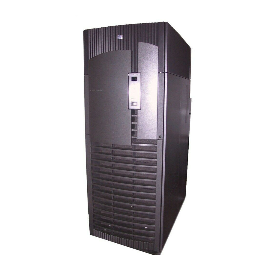
Overview Basic System Building Blocks Basic System Building Blocks The basic system building blocks used to configure a hp Integrity Superdome system are as follows: • Server cabinet • Support Management Station Figure 1-2 on page 5 illustrates a typical SD16 or SD32 installation. Figure 1-3 on page 6 illustrates a typical SD64 installation. - Page 16 Overview Basic System Building Blocks Figure 1-1 Server Cabinet Components Fans Cell Boards I/O Chassis I/O Fans PDCA Chapter 1...
- Page 17 Overview Basic System Building Blocks Figure 1-2 Typical SD32 Installation Chapter 1...
- Page 18 Overview Basic System Building Blocks Figure 1-3 Typical SD64 Installation Chapter 1...
- Page 19 Overview Basic System Building Blocks Figure 1-4 Typical Installation with IOX Support Management Station The new SMS is an hp Proliant M350-G3 rack-mount version, which includes the TFT-5600 LCD rack-mount display and keyboard. Chapter 1...
-
Page 20: Configuration Rules
Overview Configuration Rules Configuration Rules The hp Integrity Superdome and/or hp 9000 Superdome rules for configuration are as follows: • Single-cabinet system: — Two to 32 CPUs per complex with single-core processors — Four to 64 CPU cores per complex with dual-core processors —... -
Page 21: Utilities Subsystem
Overview Utilities Subsystem Utilities Subsystem Both types of servers contain a group of boards that together form the Utilities subsystem. These include: • UGUY • SBCH—Single Board Computer Hub • SBC—Single Board Computer • HUCB—HalfDome Utility Connector Board UGUY The UGUY board is a major component of the utility subsystem. It provides the following functions: •... -
Page 22: Cell Board
Overview Cell Board Cell Board The cell board with its firmware is the biggest change to the Superdome family. It provides the processing and memory resources required by each hp Integrity Superdome system configuration. Each cell board uses up to four Itanium®... -
Page 23: Cell Controller
Overview Cell Board Figure 1-6 Cell Board Functional Block Diagram Cell Controller The CC has five major interfaces: • Processor (two independent FSBs) • Crossbar (cell interconnect fabric) • Remote I/O link • Memory subsystem • Platform-dependant hardware (PDH) Using an internal, centralized data path, the CC maintains cache coherency throughout the system with memory tags. -
Page 24: Remote I/O Link
Overview Cell Board either 18 or 19 bits. The other four bundles are used for output data and are also either 18 or 19 bits in width. The crossbar link has a built-in link presence detect capability that effectively prevents either the CC or the crossbar from driving signals into an unpowered device on the opposite side of the link. -
Page 25: Cell Power Board
Overview Cell Board — 12-MB FLASH EPROM for system firmware boot-strap code storage — 1-MB system firmware scratch pad SRAM for operation instruction and data storage — 512-KB battery backed Non-Volatile RAM (NVRAM) — Wall-clock information provided by a battery-backed real-time clock (RTC) chip —... -
Page 26: Pci-X I/O
Overview PCI-X I/O PCI-X I/O The new PCI-X I/O chassis holds PCI and PCI-X type I/O cards for the two new systems. Older Superdome systems used only the PCI cards and card cages. The chassis consists of the following three printed circuit assemblies: PCI-X I/O Backplane PCI-X I/O Power Board... -
Page 27: Pci-X Power Board
Overview PCI-X I/O Figure 1-8 I/O Subsystem Architecture PCI-X Power Board The PCI-X power board (PCI-X PB) contains six DC-DC converters, over-voltage protection, filter components, in-rush current limiting circuitry, the local power monitor (GIOLPM) CPLD, and various status and control logic devices. -
Page 28: Pci-X Transfer Board
Overview PCI-X I/O PCI-X Transfer Board The PCI-X I/O transfer board connects several power sources and utilities signals from the PCI-X PB to the PCI-X I/O backplane. Core I/O Core I/O refers to the base set of I/O functions required by every partition. The core I/O card uses a standard full-length PCI-X form factor but adds a secondary edge connector in line with its PCI-X connector. -
Page 29: System Backplane
Overview System Backplane System Backplane There are two backplane boards: the HLSB (Left Backplane) and the HRSB (Right Backplane). For a single-cabinet system the determination is not relevant, but in a two-cabinet system it is. Whether a system has either a left or right backplane depends on the location of the system in an SD64 complex. Each backplane has a “flex”... -
Page 30: Front Panel Display Cell Ol* Led
Overview Front Panel Display Cell OL* LED Front Panel Display Cell OL* LED The Front Panel board (FPB) is located on the front skins and is accessible to the user. It contains the power ON/OFF switch, a decimal display for cabinet numbers between 0 and 15, and LED's for +5 V Power Good, +48 V Power Good, MP Present, Remote, and Attention. -
Page 31: Firmware
(POSSE). The POSSE shell is based on the EFI standard shell. Several commands have been added to the standard EFI shell to support Hewlett-Packard value-added functionality. The new commands encompass functionality similar to BCH commands on PA-RISC machines. However, the POSSE shell is not designed to encompass all BCH functionality. - Page 32 Overview Firmware Chapter 1...
-
Page 33: Installing The System
Installing the System This chapter describes installation of a new hp Integrity Superdome or hp 9000 Superdome systems. It is assumed that the installer has received adequate training and is knowledgeable with the product and has a good, overall background in electronics and customer hardware installation. Chapter 2... -
Page 34: Introduction
Installing the System Introduction Introduction The instructions in this guide are written for Customer Engineers (CEs) who are experienced at installing complex systems. If installing an hp Integrity Superdome or hp 9000 Superdome for the first time, read this manual. It provides details about each step in the installation process. -
Page 35: Unpacking And Inspecting
Installing the System Unpacking and Inspecting Unpacking and Inspecting This section describes what to do before unpacking the server and how to unpack the system itself. WARNING Do not attempt to move the cabinet, either packed or unpacked, up or down an incline of more than 15 Verifying Site Preparation Verifying site preparation includes two tasks: gathering LAN information and verifying electrical... -
Page 36: Inspecting The Shipping Containers For Damage
Installing the System Unpacking and Inspecting Inspecting the Shipping Containers for Damage HP shipping containers are designed to protect their contents under normal shipping conditions. After the equipment arrives at the customer site, carefully inspect each carton for signs of shipping damage. WARNING Do not attempt to move the cabinet, either packed or unpacked, up or down an incline of more than 15... - Page 37 Installing the System Unpacking and Inspecting A tilt indicator is installed on the back and side of the cabinet shipping container. If the container has been tilted to an angle that could cause equipment damage, the beads in the indicator shift positions. If a carton has received a physical shock and the tilt indicator is in an abnormal condition, visually inspect the unit for any signs of damage.
-
Page 38: Unpacking And Inspecting Hardware Components
If the shipment is incomplete, the equipment is damaged, or it fails to meet specifications, notify the nearest Hewlett-Packard Sales and Service Office. If damage occurred in transit, notify the carrier as well. Hewlett-Packard will arrange for replacement or repair without waiting for settlement of claims against the carrier. - Page 39 CAUTION Use three people to unpack the cabinet safely. Hewlett-Packard recommends removing the cardboard shipping container before moving the cabinet into the computer room. If unpacking the cabinet in the computer room, be sure to position it so that it can be moved NOTE into its final position easily.
- Page 40 Installing the System Unpacking and Inspecting Figure 2-4Cutting Polystrap Bands Hold Here Cut Here Polystrap Bands Step 3. Lift the cardboard corrugated top cap off of the shipping box. Step 4. Remove the corrugated sleeves surrounding the cabinet. Step 5. Remove the stretch wrap, the front and rear top foam inserts, and the four corner inserts from the cabinet.
- Page 41 Installing the System Unpacking and Inspecting Figure 2-5Removing the Ramps from the Pallet Ramps Chapter 2...
- Page 42 Some damage can be repaired by replacing the damaged part. If extensive damage is found, it may be necessary to repack and return the entire cabinet to Hewlett-Packard. Check the cabinet exterior for signs of shipping damage.
- Page 43 Installing the System Unpacking and Inspecting Step 3. Check to see that the I/O chassis mounting screws are in place and secure. Figure 2-7I/O Chassis Mounting Screws Mounting Screws I/O Chassis I/O chassis Check all components for signs of shifting during shipment or any signs of damage. Step 4.
- Page 44 Installing the System Unpacking and Inspecting Figure 2-8Remove BPS Shipping Strap Remove BPS Shipping Strap Step 5. Remove the pallet mounting brackets and pads on the side of the pallet where the ramp slots are located. Figure 2-9Removing the Mounting Brackets Chapter 2...
- Page 45 Installing the System Unpacking and Inspecting Step 6. On the other side of the pallet, remove only the bolt on each mounting bracket that is attached to the cabinet. Do not remove the bolts on the mounting brackets that attach to the pallet. WARNING These bolts prevent the cabinet from rolling off the back of the pallet.
-
Page 46: Unpacking The Pdca
Installing the System Unpacking and Inspecting Step 8. Carefully roll the cabinet down the ramp. Figure 2-11Rolling the cabinet Down the Ramp WARNING Do not attempt to move the cabinet, either packed or unpacked, up or down an incline of more than 15 Step 9. -
Page 47: Returning Equipment
Returning Equipment If the equipment is found to be damaged, use the original packing material to repackage the cabinet for shipment. If the packing material is not available, contact the local Hewlett-Packard Sales and Support Office regarding shipment. Before shipping, place a tag on the container (or equipment) to identify the owner and the service to be performed. - Page 48 Installing the System Unpacking and Inspecting Repackaging: Step 1. Assemble the Hewlett-Packard packing materials that came with the cabinet. Step 2. Carefully roll the cabinet up the ramp. Step 3. Attach the pallet mounting brackets to the pallet and the cabinet.
-
Page 49: Setting Up The Hp Integrity Superdome Or Hp 9000 Superdome
Installing the System Setting Up the hp Integrity Superdome or hp 9000 Superdome Setting Up the hp Integrity Superdome or hp 9000 Superdome After a site has been prepared, the system has been unpacked, and components have been inspected, the system can now be prepared for booting. - Page 50 Installing the System Setting Up the hp Integrity Superdome or hp 9000 Superdome This cardboard protects the housing baffle during shipping. If it is not removed, the fans will not work properly. Figure 2-13Removing Protective Cardboard from the Housing NOTE Double-check that the protective cardboard has been removed.
- Page 51 Installing the System Setting Up the hp Integrity Superdome or hp 9000 Superdome Step 4. Using the handles on the housing labeled Blower 0 Blower 1, part number A5201-62030, align the edge of the housing over the edge at the top front of the cabinet, and slide it into place until the connectors at the back of each housing are fully mated;...
-
Page 52: Attaching Side Skins And Blower Side Bezels
Installing the System Setting Up the hp Integrity Superdome or hp 9000 Superdome Step 7. Tighten the thumbscrews at the front of each blower. Step 8. If required, install housings on any other cabinets that were shipped with the system. Attaching Side Skins and Blower Side Bezels There are two cosmetic side panels that affix to the left and right sides of the system. - Page 53 Installing the System Setting Up the hp Integrity Superdome or hp 9000 Superdome Step 3. Attach the skin without the lap joint (front) over the top bracket and under the bottom bracket and gently slide the skin into position. Figure 2-18Attaching the Front Side Skins Step 4.
- Page 54 Step 3. Lower the bezel so the bezel top lip fits securely on the blower housing frame and the two lower tabs are fully inserted into the side panel slots. Step 4. Using a Torx 10 drive, attach the screws (Hewlett-Packard P/N 0515-4271) to secure the skins to the brackets.
-
Page 55: Attaching The Leveling Feet And Leveling The Cabinet
Step 5. Repeat Step 1 through Step 4 for the skins on the other side of the cabinet. Step 6. To secure the side bezels to the side skins, attach the blower bracket locks (Hewlett-Packard P/N A5201-00268) to the front and back blowers using a T20 Torx driver. - Page 56 Figure 2-21Installing the Lower Front Door Assembly Step 4. Using a Torx 10 driver, secure the lower door bezel to the front door chassis with 10 of the screws provided (Hewlett-Packard P/N 0515-0372). Insert all screws loosely, then torque them after the bezel is aligned.
- Page 57 Installing the System Setting Up the hp Integrity Superdome or hp 9000 Superdome Figure 2-22Installing the Upper Front Door Assembly Front Panel Display Cable Step 6. Feed the grounding strap through the door and attach it to the cabinet. Step 7. Insert the shoulder studs on the upper door bezel into the holes on the front door metal chassis. Step 8.
- Page 58 Installing the System Setting Up the hp Integrity Superdome or hp 9000 Superdome Figure 2-23Installing the Rear Blower Bezel Step 3. Align the bezel over the nuts that are attached to the bracket at the rear of the cabinet. Step 4. Using a T20 Torx driver, tighten the two captive screws on the lower flange of the bezel. Tighten the screws securely, otherwise the screw may interfere with the door.
-
Page 59: Installing And Verifying The Pdca
Installing the System Setting Up the hp Integrity Superdome or hp 9000 Superdome Figure 2-24Installing the Front Blower Bezel Step 3. Align the bezel over the nuts that are attached to the bracket at the front of the cabinet. Step 4. Using a T20 Torx driver, tighten the two captive screws on the lower flange of the bezel. Tighten the screws securely, otherwise the screw may interfere with the door. - Page 60 Installing the System Setting Up the hp Integrity Superdome or hp 9000 Superdome Figure 2-25 PDCA Assembly for Options 6 and 7 Figure 2-26 Four-Wire Connector Chapter 2...
- Page 61 Installing the System Setting Up the hp Integrity Superdome or hp 9000 Superdome Figure 2-27 Five-Wire Connector Use the following procedure to install the PDCA: Step 1. Make sure the circuit breaker on the PDCA is Off. Step 2. Remove the rear PDCA bezel by removing the four retaining screws. Step 3.
- Page 62 Installing the System Setting Up the hp Integrity Superdome or hp 9000 Superdome Figure 2-28Installing the PDCA Step 5. Using a T20 Torx driver, attach the four screws that hold the PDCA in place. Step 6. If required, repeat Step 3 through Step 5 for the second PDCA. Step 7.
- Page 63 Installing the System Setting Up the hp Integrity Superdome or hp 9000 Superdome Figure 2-29 Checking PDCA Test Points (5-Wire) See Detail Detail B Detail A Test Points Retaining Screw Table 2-3 4- and 5-Wire Voltage Ranges 4-Wire 5-Wire L2 to L3: 200-240 V L1 to N: 200-240 V L2 to L1: 200-240 V L2 to N: 200-240 V...
-
Page 64: Removing The Emi Panels
Installing the System Setting Up the hp Integrity Superdome or hp 9000 Superdome Removing the EMI Panels Remove the front and back electromagnetic interference (EMI) panels to access ports and to visually check whether components are in place and the LEDs are properly illuminated when power is applied to the system. To remove the front and back EMI panels: Step 1. -
Page 65: Connecting The Cables
Installing the System Setting Up the hp Integrity Superdome or hp 9000 Superdome Figure 2-31Removing the Back EMI Panel Back EMI Panel Screw Step 4. Use the handle provided to gently remove the EMI panel; then, set it aside. Connecting the Cables The I/O cables are attached and tied inside the cabinet. -
Page 66: Routing I/O Cables
Installing the System Setting Up the hp Integrity Superdome or hp 9000 Superdome Figure 2-32 Cable Labeling Routing I/O Cables Routing the cables is a significant task in the installation process. It is important not only for the immediate need of completing the installation, but efficient cable routing is important when future service calls are made. - Page 67 Installing the System Setting Up the hp Integrity Superdome or hp 9000 Superdome Figure 2-33 Routing I/O Cables Use the following procedure and guidelines to route cables through the cable groomer at the bottom rear of the cabinet. Step 1. Remove the cable access plate at the bottom of the groomer. Step 2.
- Page 68 Installing the System Setting Up the hp Integrity Superdome or hp 9000 Superdome 5. Repeat the above pattern until all of the cables are routed. Step 3. Connect the Management Processor (MP) cables last. Step 4. Reattach the cable access plate at the bottom of the cable groomer. Step 5.
-
Page 69: Connecting The Mp To The Customer Lan
Installing the System Connecting the MP to the Customer LAN Connecting the MP to the Customer LAN This section discusses how to connect, set up, and verify the Superdome MP to the customer LAN. LAN information includes the MP network name (host name), the MP IP address, the subnet mask, and gateway address. -
Page 70: Setting Customer Ip Address
Installing the System Connecting the MP to the Customer LAN Setting Customer IP Address NOTE The default IP address for the Customer LAN port on the MP is 192.168.1.1. To set the customer LAN IP address: Step 1. From the MP Command Menu prompt (MP:CM>), enter lc (for LAN Configuration). The screen displays the default values and asks if you want to modify them. - Page 71 Installing the System Connecting the MP to the Customer LAN This is the host name for the customer LAN. You can use any name you like. The name can be as many as 64 characters, and include alpha numerics, - (dash), _ (under bar), . (period), or a space. It is recommended that the name be a derivative of the complex name.
-
Page 72: Turning On Housekeeping Power
Installing the System Turning On Housekeeping Power Turning On Housekeeping Power Step 1. Verify that the AC voltage at the input source is within specifications for each cabinet being installed. Step 2. Ensure that: • The AC breakers are in the Off position. See Figure 2-37. •... - Page 73 Installing the System Turning On Housekeeping Power Figure 2-37Front Panel Display with Housekeeping (HKP) Power On, and Present Indicators HKP, Present, and Attention Lights Step 5. Check the BPS LEDs. When on, the breakers on the PDCA distribute power to the BPSs. AC power is present at the BPSs when: •...
- Page 74 Installing the System Turning On Housekeeping Power Figure 2-38BPS LEDs BPS LEDs Chapter 2...
-
Page 75: Booting And Verifying The System
Installing the System Booting and Verifying the System Booting and Verifying the System After the system has been installed, it should be verified that the proper hardware is installed and booted. This section describes how to power on the cabinet; and boot and test each partition. A console window must be open for each partition. - Page 76 Installing the System Booting and Verifying the System The MP main menu appears as shown in Figure 2-40. Figure 2-40Main MP Menu Step 3. Repeat the first two steps for each partition required. Step 4. In one window, bring up the command prompt by entering cm at the MP prompt, as shown in Figure 2-41.
- Page 77 Installing the System Booting and Verifying the System Figure 2-42MP Virtual Front Panel Step 6. From the VFP menu, enter s to select the whole system or the partition number to select a particular partition. An output similar to that shown in Figure 2-43 should appear. In this example, no status should be listed, because the system 48 volts has not been switched on.
-
Page 78: Powering On The System 48 Volts
Installing the System Booting and Verifying the System Figure 2-44MP Console Option Powering on the System 48 Volts Step 1. Switch on the 48-volt supply from each cabinet front panel. If the complex has an IOX cabinet, power on this cabinet first. In a large complex cabinets should be powered on in one of the two following orders: 9, 8, 1, 0 or 8, 9, 0, 1. -
Page 79: Booting Hp Integrity Superdome To Efi Shell
Installing the System Booting and Verifying the System Booting hp Integrity Superdome to EFI Shell After powering on (or using the CM bo command), all partition console windows will show activity while the firmware is initialized and will stop momentarily at an Boot Manager menu. Figure 2-45hp Integrity Superdome EFI Boot Manager Use the up-down arrows on the keyboard to highlight EFI Shell (Built-in) and press enter. - Page 80 Installing the System Booting and Verifying the System Figure 2-46 EFI Shell Prompt NOTE If autoboot is enabled for an nPartition, it must be interrupted to stop the boot process at the firmware console: EFI on hp Integrity Superdome and BCH on hp 9000 Superdome. At this point, the virtual front panel indicates that each partition is at system firmware console as indicated in Figure 2-47.
-
Page 81: Booting Hp 9000 To Bch Shell
Installing the System Booting and Verifying the System Figure 2-47 hp Integrity Superdome Partitions at System Firmware Console Booting hp 9000 to BCH Shell After powering on (or using the CM bo command), all partition console windows will show activity while the firmware is initialized and will stop at the BCH menu shown in Figure 2-48. -
Page 82: Verifying The System
Installing the System Booting and Verifying the System At this point, the virtual front panel indicates that each partition is at system firmware console as indicated in Figure 2-49. Figure 2-49 hp 9000 Superdome Virtual Front Panel Verifying the System Step 1. - Page 83 Installing the System Booting and Verifying the System Step 2. At the “Select Device” prompt, enter B then the cabinet number to check the power status of the cabinet. Observe that the Power Switch: on and Power: enabled as shown in Figure 2-51. Figure 2-51Power Status Window Figure 2-51 shows that cells are installed in slots 0 and 4.
- Page 84 Installing the System Booting and Verifying the System Step 4. Verify that there is an * in the columns marked MP, CLU, and PM. IMPORTANT An * appears in the MP column only for cabinet 0; that is, the cabinet containing the MP. There is only one cabinet that contains the MP, and that is cabinet 0.
-
Page 85: Running Jet Software
Installing the System Running JET Software Running JET Software The JTAG Utility for Scan Tests (JUST) Exploration Tool, or JET, collects system information for each system on a network and places it in files for use by other scan tools. JET gathers configuration data by executing a series of queries targeted at the MP and the CLU portion of the UGUY board. -
Page 86: Attaching Rear Kick Plates
Installing the System Attaching Rear Kick Plates Attaching Rear Kick Plates Kick plates serve the practical purpose of protecting cables from accidentally being disconnected or damaged, as well as add an attractive cosmetic touch to the cabinet. There are three metal pieces to attach to the bottom rear of the cabinet. -
Page 87: Performing A Visual Inspection And Completing The Installation
Installing the System Performing a Visual Inspection and Completing the Installation Performing a Visual Inspection and Completing the Installation After booting the system, carefully inspect it and reinstall the EMI covers. Here are the steps required to perform a final inspection and complete the installation: Step 1. - Page 88 Installing the System Performing a Visual Inspection and Completing the Installation Figure 2-55Front EMI Panel Flange and cabinet Holes Hole Flange See Detail 2. Position the panel at the top lip and lift the panel up while pushing the bottom into position. The EMI gasket may have to be compressed to get the panel to seat properly.
- Page 89 Installing the System Performing a Visual Inspection and Completing the Installation Figure 2-56Attaching Front EMI Panel Front EMI Panel Screw Step 5. Check that the cables inside the rear enclosure are secure. Step 6. Reinstall the back EMI panel. 1. Align the lip inside the cabinet with the lip on the EMI Panel. Chapter 2...
- Page 90 Installing the System Performing a Visual Inspection and Completing the Installation Figure 2-57Reinstalling the Back EMI Panel Cabinet EMI Panel Lip Panel Lip 2. Push the EMI panel up and in. The EMI gasket may have to be compressed at the top of the enclosure to get the panel to seat properly.
-
Page 91: Post-System-Installation Check
Enter information in the Gold Book. When the installation and cleanup are complete, make the appropriate notations in the Gold Book, which should have been shipped with the system. • Obtain customer acceptance (if required). This includes thanking the customer for choosing Hewlett-Packard. Chapter 2... - Page 92 Installing the System Post-System-Installation Check Chapter 2...
-
Page 93: Removing And Replacing Components
Removing and Replacing Components Chapter 3... -
Page 94: Powering Down And Powering Up The System
Removing and Replacing Components Powering Down and Powering Up the System Powering Down and Powering Up the System Throughout this chapter, as well as in other places in this book, there steps that require powering down or power up the system. All instructions for these task are covered in Appendix B, “Powering On and Off the System,”... -
Page 95: Removing And Replacing The Cabinet Side Skins
Removing and Replacing Components Removing and Replacing the Cabinet Side Skins Removing and Replacing the Cabinet Side Skins The cabinet side skins are identical for the right and left sides. There are four side skins, two on each side. These skins are easily replaced. Figure 3-1 Cabinet Side Skins location Side Skins... -
Page 96: Removing The Cabinet Side Skins
Removing and Replacing Components Removing and Replacing the Cabinet Side Skins Removing the Cabinet Side Skins Figure 3-2 Cabinet Side Skins Detail Slide the first cabinet side skin forward and off the cabinet rail. If both skins are to be removed from one side, repeat this step. -
Page 97: Removing And Replacing The Front Electromagnetic Interference (Emi) Cover
Removing and Replacing Components Removing and Replacing the Front Electromagnetic Interference (EMI) Cover Removing and Replacing the Front Electromagnetic Interference (EMI) Cover There is an EMI (Electromagnetic Interference) cover on the front of the cabinet. This cover is secured with one captive screw in the lower center of the cover. -
Page 98: Removing And Replacing The Rear Electromagnetic Interference (Emi) Cover
Removing and Replacing Components Removing and Replacing the Rear Electromagnetic Interference (EMI) Cover Removing and Replacing the Rear Electromagnetic Interference (EMI) Cover There is an EMI (Electromagnetic Interference) cover on the rear of the cabinet. This cover is secured with one captive screw in the lower center of the cover. -
Page 99: Replacing The Rear Emi Cover
Removing and Replacing Components Removing and Replacing the Rear Electromagnetic Interference (EMI) Cover Figure 3-4 Rear EMI Cover Detail Replacing the Rear EMI Cover The rear cover is held in place at the top by a channel in the cover that slides into a lip on the chassis. Step 1. - Page 100 Removing and Replacing Components Removing and Replacing the Rear Electromagnetic Interference (EMI) Cover Figure 3-5 Rear EMI Cover Installation Chapter 3...
-
Page 101: Removing And Replacing The Side Emi Covers (For A Two Cabinet System)
Removing and Replacing Components Removing and Replacing the Side EMI Covers (for a two cabinet system) Removing and Replacing the Side EMI Covers (for a two cabinet system) There are two EMI covers on the sides of the cabinet. These covers are in place for the cable configuration in a two cabinet system. -
Page 102: Removing And Replacing The Bulk Power Supply (Bps)
Removing and Replacing Components Removing and Replacing the Bulk Power Supply (BPS) Removing and Replacing the Bulk Power Supply (BPS) The Bulk Power Supply (BPS) is located in the front end power system (FEPS). The BPS is an N+1 component and is easily replaced. -
Page 103: Replacing The Bulk Power Supply
Removing and Replacing Components Removing and Replacing the Bulk Power Supply (BPS) Replacing the Bulk Power Supply Step 1. Grip the handle with one hand while supporting the rear of the BPS in the other hand and insert the BPS into the same slot from which it was removed. Step 2. -
Page 104: Installing An Additional Power Distribution Control Assembly
Removing and Replacing Components Installing An Additional Power Distribution Control Assembly Installing An Additional Power Distribution Control Assembly Adding additional capacity to an existing system requires careful consideration and planning. A Solution Implementation Plan (SIP) should be developed before visiting the customer site. Figure 3-7 shows a cabinet with both PDCAs installed. - Page 105 Removing and Replacing Components Installing An Additional Power Distribution Control Assembly 1. Run the power cord down through the appropriate opening in the floor tile. 2. Partially insert the PDCA into its slot. 3. Slip the L bracket under the power cord on the rear of the PDCA. 4.
-
Page 106: Removing And Replacing The Front-End Power Supply
Removing and Replacing Components Removing and Replacing the Front-End Power Supply Removing and Replacing the Front-End Power Supply To remove the Front-End Power Supply (FEPS), turn off all breakers and remove power from the wall panel. Remove all PDCAs and BPSs. Mark and remove all cables from the FEPS. Slide out the old FEPS and replace with the new one. - Page 107 Removing and Replacing Components Removing and Replacing the Front-End Power Supply Figure 3-9Removing the BPSs Step 4. Remove the rear PDCA Bezel. This exposes the cable groomer. Chapter 3...
- Page 108 Removing and Replacing Components Removing and Replacing the Front-End Power Supply Figure 3-10PDCA Locations L Bezel PDCA0 Rear PDCA Bezel PDCA1 L Bezel Step 5. Remove PDCAs using the following procedure for each. 1. Remove the L bezel. 2. Using a T15 Torx driver, loosen the four captive screws that hold the PDCA in place. 3.
- Page 109 Removing and Replacing Components Removing and Replacing the Front-End Power Supply Figure 3-11Removing the PDCAs Chapter 3...
- Page 110 Removing and Replacing Components Removing and Replacing the Front-End Power Supply Step 6. Remove the cable groomer by removing the four Torx T20 screws that secure it in the cabinet. Figure 3-12Removing the Cable Groomer Step 7. Unplug the two cables from the FEPS. Chapter 3...
- Page 111 Removing and Replacing Components Removing and Replacing the Front-End Power Supply Figure 3-13Removing the Cables and Bus Bar Hardware from the FEPS Remove cables from these connectors Remove 3/8-inch nuts to remove power cables Rear View of Cabinet Step 8. Remove the 3/8-inch nuts and washers securing the heavy leads onto the power busbar and mark and remove all of the leads (four heavy leads and two sense lines).
-
Page 112: Replacing The Feps
Removing and Replacing Components Removing and Replacing the Front-End Power Supply Step 9. Remove the four Torx T20 screws securing the FEPS to the front of the cabinet. Figure 3-14Removing the FEPS Step 10. Grasp the FEPS chassis and remove it from the cabinet Step 11. - Page 113 Removing and Replacing Components Removing and Replacing the Front-End Power Supply Figure 3-15Removing the BPSs Chapter 3...
- Page 114 Removing and Replacing Components Removing and Replacing the Front-End Power Supply Step 5. Re-attach the four heavy cables and two sense wires previously marked to the appropriate studs on the FEPS. Figure 3-16 Re-attaching Power Leads and Cables Attach cables to these connectors Attach power cables and tighten 3/8-inch nuts...
-
Page 115: Removing And Replacing The I/O Fan Module
Removing and Replacing Components Removing and Replacing the I/O Fan Module Removing and Replacing the I/O Fan Module There are five individual I/O Fan Modules located in the center of each SD32000 cabinet. They are labeled 0 to 4 and are easily replaced from the front of the cabinet. See Figure 3-17. I/O fan failures are detected by logic on the (UGUY) within the cabinet. -
Page 116: Removing The I/O Fan Module
Removing and Replacing Components Removing and Replacing the I/O Fan Module Removing the I/O Fan Module This Section contains information on removing an I/O Fan Module Figure 3-18 I/O Fan Module Detail Step 1. Locate the failed fan module. The fan modules are numbered 0 to 4 left to right. The failed fan will have the “fan operating”... -
Page 117: Removing And Replacing The I/O Fan Mounting Frame
Removing and Replacing Components Removing and Replacing the I/O Fan Mounting Frame Removing and Replacing the I/O Fan Mounting Frame The I/O fan mounting frame holds the five I/O fans and is located in the front of the server. The server must be shut down to perform this task. -
Page 118: Removing And Replacing The Air Filter
Removing and Replacing Components Removing and Replacing the Air Filter Removing and Replacing the Air Filter SuperDome air filters are located on the inside of the front and rear door assemblies. These filters are easily replaced. Figure 3-19 Front Air Filter Location Front Door Air Filters Chapter 3... -
Page 119: Removing The Air Filters
Removing and Replacing Components Removing and Replacing the Air Filter Figure 3-20 Rear Air Filter Location Rear Door Air Filter Removing the Air Filters Step 1. Remove the filter media from the housing. Step 2. Using proper ESD procedures, vacuum clean the filter media area. Replacing the Air Filters Step 1. -
Page 120: Removing And Replacing The Blower Side Bezels
Removing and Replacing Components Removing and Replacing the Blower Side Bezels Removing and Replacing the Blower Side Bezels The cabinet has two blower side bezels. These are cosmetic covers for the blowers and are located on the right and left side of the blower module housing. The blower side bezels are easily replaced. Figure 3-21 Blower Side Bezel Locations Side Bezels... -
Page 121: Replacing The Blower Side Bezel
Removing and Replacing Components Removing and Replacing the Blower Side Bezels The right and left blower side bezels are removed using the same procedure. Figure 3-22 Blower Side Bezel Detail Step 1. Remove the front and rear blower bezels. Step 2. Remove the side blower bezel brackets from front and rear to release the side blower bezel. Step 3. -
Page 122: Removing And Replacing The Rear Blower Bezel
Removing and Replacing Components Removing and Replacing the Rear Blower Bezel Removing and Replacing the Rear Blower Bezel The Rear Blower Bezel is a cosmetic cover for the blowers and is located above the rear door. The Rear Blower bezel is easily replaced. Figure 3-23 Rear Blower Bezel Location Rear Blower Bezel... -
Page 123: Removing The Rear Blower Bezel
Removing and Replacing Components Removing and Replacing the Rear Blower Bezel Removing the Rear Blower Bezel Figure 3-24 Rear Blower Bezel Detail Step 1. Loosen the two captive T-20 screws on the lower flange of the bezel. Step 2. Lift the bezel up and off of the blower housing frame. Step 3. -
Page 124: Removing And Replacing The Blower Module
Removing and Replacing Components Removing and Replacing the Blower Module Removing and Replacing the Blower Module SuperDome cabinets have four blower modules located on the top of the cabinet. Blowers 0 and 1 are located in the front of the cabinet and Blowers 2 and 3 are located in the rear. These modules are in an N+1 configuration and may be “hot swapped.”... -
Page 125: Removing The Blower Module
Removing and Replacing Components Removing and Replacing the Blower Module Removing the Blower Module This section contains information on removing a blower module. Figure 3-26 Blower Removal Detail Step 1. Remove the blower bezel at the front or rear of the server. Step 2. - Page 126 Removing and Replacing Components Removing and Replacing the Blower Module Chapter 3...
-
Page 127: System Specifications
System Specifications The following specifications are based on HP Environmental Class C2. Class C2 is a controlled computer room environment where products are subject only to controlled temperature and humidity extremes. Throughout this chapter each specification is defined as thoroughly as possible to ensure that all data is considered to ensure a successful site preparation and system installation. -
Page 128: Dimensions And Weights
System Specifications Dimensions and Weights Dimensions and Weights Component Dimensions Table 4-1 lists the dimensions for the cabinet and components. Table 4-2 list the dimensions for optional IOX cabinets. Table 4-1 Server Component Dimensions Maximum Width Depth Height Component Quantity per (in. -
Page 129: Component Weights
System Specifications Dimensions and Weights Component Weights Table 4-3 lists the server and component weights. NOTE Refer to the appropriate documents to determine the weight of the SMS and any console that will be used with this server. Table 4-3 System Component Weights Weight Per Component... -
Page 130: Shipping Dimensions And Weights
System Specifications Dimensions and Weights Shipping Dimensions and Weights Table 4-5 lists the dimensions and weights of the Support Management Station and a single cabinet with shipping pallet. Table 4-5 Miscellaneous Dimensions and Weights Width Depth/Length Height Weight Equipment (in. / cm) (in. -
Page 131: Electrical Specifications
System Specifications Electrical Specifications Electrical Specifications The following specifications are based on HP Environmental Class C2. Class C2 is a controlled computer room environment where products are subject only to controlled temperature and humidity extremes. Throughout this chapter each specification is defined as thoroughly as possible to ensure that all data is considered to ensure a successful site preparation and system installation. - Page 132 System Specifications Electrical Specifications a. A dedicated branch circuit is required for each PDCA installed. Table 4-7 Option 6 and 7 Specifics PDCA Receptacle Attached Power Cord Attached Plug Part Number Required A5201-69023 OLFLEX 190 (PN 600804) is a 2.5 meter multi Mennekes Mennekes (Option 6)
-
Page 133: System Power Requirements
System Specifications Electrical Specifications Figure 4-1 PDCA Locations System Power Requirements Table 4-8 and Table 4-9 list the AC power requirements for a hp Integrity Superdome and hp 9000 Superdome systems. These tables provide information to help determine the amount of AC power needed for your computer room. -
Page 134: Component Power Requirements
System Specifications Electrical Specifications Table 4-8 Power Requirements (without Support Management Station) Requirements Value Comments Product Label maximum current, 24 (A rms) Per phase at 200-240VAC three-phase, five-wire Power factor correction 0.95 minimum Ground leakage current (mA) > 3.5 ma See WARNING below. -
Page 135: I/O Expansion Cabinet Power Cords
System Specifications Electrical Specifications Table 4-10 I/O Expansion Cabinet Power Requirements (without Support Management Station) Requirements Value Nominal input voltage 200/208/220/230/240 (VAC rms) Input voltage range (minimum-maximum) 200-240 (VAC rms) Frequency range (minimum-maximum) 50/60 (Hz) Number of phases Marked Electrical input current Maximum inrush current 60 max (A peak) Power factor correction... -
Page 136: Environmental Requirements
System Specifications Environmental Requirements Environmental Requirements This section provides the environmental, power dissipation, noise emission, and air flow specifications. Temperature and Humidity Specifications Table 4-13 Controlled Computer Room Environment Specifications Relative Humidity %; Rate of Chg Temperature (dry bulb C) Dew Point Noncondensing (°C/hr, max) - Page 137 System Specifications Environmental Requirements Table 4-15 Typical hp Integrity Superdome Configurations Breaker 3-Pole Breaker 4-Pole Breaker Typical Cooling Power Size Size Cell Memory (Watts) (BTU/Hr.) a,c,d (Watts) (Amperes) (Amperes) 9790 33406 12335 8450 28834 10647 8680 29619 10937 8170 27878 10294 8400 28663...
- Page 138 System Specifications Environmental Requirements c. An input power source supplied from a three-pole plus PE, four-wire system may be wired as either: 200VAC phase-to-phase, plus a PE ground. The three phase input voltage to the equipment is connected phase-to-phase. The neutral terminal in the PDCA is not connected. 208VAC phase-to-phase, plus a PE ground.
- Page 139 System Specifications Environmental Requirements Table 4-16 Typical hp 9000 Superdome Configurations Breaker 3-Pole Breaker 4-Pole Breaker Typical Cooling Power Size Size Cell Memory (Watts) (BTU/Hr.) a,c,d (Watts) (Amperes) (Amperes) 9038 30840 11388 7698 26268 9699 7928 27053 9989 7418 25312 9347 7648 26097...
- Page 140 System Specifications Environmental Requirements c. An input power source supplied from a three-pole plus PE, four-wire system may be wired as either: 200VAC phase-to-phase, plus a PE ground. The three phase input voltage to the equipment is connected phase-to-phase. The neutral terminal in the PDCA is not connected. 208VAC phase-to-phase, plus a PE ground.
-
Page 141: Acoustic Noise Specification
System Specifications Environmental Requirements Acoustic Noise Specification The acoustic noise specifications are as follows: • 8.2 bel (sound power level) • 65.1 dBA (sound pressure level at operator position) The above levels are appropriate for dedicated computer room environments, not office environments. Care should be taken to understand the acoustic noise specifications relative to operator positions within the computer room or when adding hp Integrity Superdome or hp 9000 Superdome systems to computer rooms with existing noise sources. -
Page 142: Air Flow
System Specifications Environmental Requirements Air Flow hp Integrity Superdome or hp 9000 Superdome systems require the cabinet air intake temperature to be between 20 C and 30 C at 2400 CFM. Any cooling system layouts described in Chapter 2 can be adapted to cool the system. -
Page 143: Site Preparation
Site Preparation Chapter 5... -
Page 144: Electrical And Environmental Guidelines
Site Preparation Electrical and Environmental Guidelines Electrical and Environmental Guidelines Electrical Factors Proper design and installation of a power distribution system for a server requires specialized skills. Those responsible for this task must have a thorough knowledge and understanding of appropriate electrical codes and the limitations of the power systems for computer and data processing equipment. - Page 145 Site Preparation Electrical and Environmental Guidelines The minimum recommended illumination level is 70 foot-candles (756 lumens per square meter) when the light level is measured at 30 inches (76.2 cm) above the floor. Power Quality This equipment is designed to operate over a wide range of voltages and frequencies. It has been tested and shown to comply with EMC Specification EN50082.
- Page 146 Having these ground connections tied to metal chassis parts that may be touched protects computer room personnel against shock hazard from current leakage and fault conditions. Power distribution systems consist of several parts. Hewlett-Packard recommends that these parts be solidly interconnected to provide an equipotential ground to all points.
- Page 147 Site Preparation Electrical and Environmental Guidelines NOTE The green wire ground conductor mentioned above may be a black wire marked with green tape. Computer Safety Ground Ground all computer equipment with the green (green/yellow) wire included in the branch circuitry. The green (green/yellow) wire ground conductors should be connected to the appropriate power panel and should be sized per applicable codes (based on circuit over current device ratings).
- Page 148 Site Preparation Electrical and Environmental Guidelines Best Practices • Use a 2ft by 2ft grid. • Flat braid is preferred over round wire. • Exothermic welds are preferred over mechanical connections. • All transformers mounted on the floor should have an X0 bond to floor. •...
-
Page 149: Environmental Elements
Site Preparation Electrical and Environmental Guidelines Wiring Connections Expansion and contraction rates vary among different metals. Therefore, the integrity of an electrical connection depends on the restraining force applied. Connections that are too tight compress or deform the hardware and causes it to weaken. This usually leads to high impedance causing circuit breakers to trip. - Page 150 Site Preparation Electrical and Environmental Guidelines • Ensure a minimum ceiling height of 12 inches between the top of the server and the ceiling. Ensure all ceiling clips are in place. Cooling Requirements Air conditioning equipment requirements and recommendations are described in the following sections. Basic Air Conditioning Equipment Requirements The cooling capacity of the installed air conditioning equipment for the computer room should be sufficient to offset the computer equipment dissipation loads, as well as any space envelope heat gain.
- Page 151 Site Preparation Electrical and Environmental Guidelines Table 5-1 Controlled Computer Room Environment Specifications Relative Humidity %; Rate of Change Temperature (dry bulb C) Dew Point Non condensing (°C/hr., max) Allowable Recommended Allowable Recommended 15 to 32 20 to 25 20 to 80 40 to 55 (59 to 90 F) (68 to 77 F)
- Page 152 Site Preparation Electrical and Environmental Guidelines An air distribution system should be zoned to deliver an adequate amount of supply air to the cooling air intake vents of the computer system equipment cabinets. Supply air temperature should be maintained within the following parameters: •...
- Page 153 Site Preparation Electrical and Environmental Guidelines Figure 5-5 on page 144 illustrates a typical computer room above ceiling ducted air distribution system (DRA). Figure 5-2 Typical Computer Room Raised Floor Layout 2’ x 2’ Grid Raised Floor Chapter 5...
- Page 154 Site Preparation Electrical and Environmental Guidelines Figure 5-3 Underfloor Air Distribution System Roof or floor slab above Ceiling cavity Ducted return air (DRA) Ceiling Down-flow A/C equipment Cooled supply air Floor cavity supply plenum Computer air intake Perforated floor panel (typical) Raised floor Floor slab Chapter 5...
- Page 155 Site Preparation Electrical and Environmental Guidelines Figure 5-4 Ceiling Plenum Air Distribution System To and From Air Handling Unit (if used) Supply Air Roof or floor Ductwork slab above Ceiling Plenum Return Air (CPRA) Return Air Grill Ceiling Diffuser Up-Flow AC Equipment Ceiling Typical Computer...
- Page 156 Site Preparation Electrical and Environmental Guidelines Figure 5-5 Above Ceiling Ducted Air To and From Air Handling Unit (if used) Supply Air Ductwork Roof Or Floor Slab Above Ducted Return Air (DRA) Return Air Grill Ceiling Diffuser Up-Flow AC Equipment Ceiling Typical Computer Air Discharge...
- Page 157 Site Preparation Electrical and Environmental Guidelines CAUTION Low humidity contributes to undesirably high levels of electrostatic charges. This increases the electrostatic discharge (ESD) voltage potential. ESD can cause component damage during servicing operations. Paper feed problems on high-speed printers are usually encountered in low-humidity environments.
- Page 158 Although this problem is relatively rare, it may be an issue within your computer room. Since metallic contamination can cause permanent or intermittent failures on your electronic equipment, Hewlett-Packard strongly recommends that your site be evaluated for metallic particulate contamination before installation of electronic equipment.
- Page 159 Site Preparation Electrical and Environmental Guidelines • Use conductive tables and chairs. • Use a grounded wrist strap (or other grounding method) when handling circuit boards. • Store spare electronic modules in antistatic containers. • Maintain recommended humidity level and airflow rates in the computer room. Acoustics Computer equipment and air conditioning blowers cause computer rooms to be noisy.
-
Page 160: Facility Guidelines
Raised-Floor Loading Raised-floor loading is a function of the manufacturer’s load specification and the positioning of the equipment relative to the raised-floor grid. While Hewlett-Packard cannot assume responsibility for determining the suitability of a particular raised-floor system, information and illustrations are provided for the customer or local agencies to determine installation requirements. - Page 161 Superdome server. Based on specific information provided by Hewlett-Packard, Tate Access Floors has approved its Series 800 all-steel access floor with bolt-together stringers and 24 in. (61.0 cm) by 24 in. (61.0 cm) floor panels.
- Page 162 Site Preparation Facility Guidelines In the event that the flooring is being replaced or a new floor is being installed, Tate Access Floors recommends its Series 1250 all-steel access floor with bolt-together stringers and 24 in. (61.0 cm) by 24 in. (61.0 cm) floor panels be used to support the Superdome installation.
-
Page 163: Space Requirements
Site Preparation Facility Guidelines Space Requirements This section contains information about space requirements for a Superdome server. This data should be used as the basic guideline for space plan developments. Other factors, such as airflow, lighting, and equipment space requirements, must also be considered. Delivery Space Requirements There should be enough clearance to move equipment safely from the receiving area to the computer room. - Page 164 Site Preparation Facility Guidelines Equipment Footprint Templates Equipment footprint templates are provided in Appendix C to show basic equipment dimensions and space requirements for servicing. Be sure to use the appropriate templates for the equipment that is to be installed. The service areas shown on the template drawings are lightly shaded.
-
Page 165: Power Options
Site Preparation Power Options Power Options Table 5-5 describes the available power options. It may be unusual to list Options 6 and 7 and not 1 and 2. The options listed are consistent with previous options for earlier Superdome systems. Table 5-5 Available Power Options Input Current... -
Page 166: Power Cords
Site Preparation Power Options Figure 5-7 PDCA Locations PDCA 0 PDCA 1 Power Cords This section discusses the different possibilities for PDCA power cords. Pre-wired PDCAs Options 6 and 7 All servers are delivered with the appropriate cable and plug. The mating in-line connector is not provided. IMPORTANT Verify that the source power is correct for the appropriate PDCA wiring. - Page 167 Site Preparation Power Options • To verify the proper wiring for a 4-wire PDCA, use a DVM to measure the voltage at the in-line connector. Voltage should read 200 - 240 Vac phase-to-phase as measured between the connector pins as follows: L1 to L2, L2 to L3, L1 to L3.
- Page 168 Site Preparation Power Options IMPORTANT Ensure that your DVM is capable of measuring AC voltages of at least 500VAC. A number of 5-wire power distribution systems may have phase-to-phase voltages in excess of 400VAC. Many hand-held volt meters are limited to 300VAC. Figure 5-9 Four-Wire In-Line Connector Figure 5-10...
- Page 169 Site Preparation Power Options Cable Removal Some installations may either require or desire that the cabinet(s) be hardwired in lieu of using the standard plugs and connectors provided. In these cases, it is necessary to remove the installed power cable from the PDCA.
- Page 170 Site Preparation Power Options Step 5. Remove the cable from the PDCA. Keep all retaining hardware for use during installation of the new cable. Figure 5-11 PDCA Cable Access (5-Wire Unit Shown) Figure 5-12 PDCA Input Wiring Connections (5-Wire Unit Shown) Ground Wire GN/YW Chapter 5...
- Page 171 Site Preparation Power Options Cable Installation NOTE These procedures may be used for early deliveries consisting of either option 1 or option 2 as well as those later systems delivered with PDCA cables attached. Select the proper cable using the following criteria. •...
- Page 172 Site Preparation Power Options To verify the proper wiring to a 5-wire PDCA, use a DVM to measure the voltage at the test points. Voltage should read 200-240VAC phase-to-neutral, as measured between the test points as follows: L1 to N, L2 to N, L3 to N. Figure 5-13 Cable Preparation Detail Dimensions shown are for a cable strain relief without an extension nipple.
- Page 173 Site Preparation Power Options NOTE Figure 5-13 shows a 4-wire cable for illustrative purposes only. 5-wire cable is dimensionally identical regarding insulation and jacket removal. The only exception is the number of conductors. Figure 5-14 PDCA (Five Wire) Input Wiring Connections 60SP041A 7/13/00 Figure 5-15...
- Page 174 Site Preparation Power Options Customer Installation Options Figure 5-16 and Figure 5-17 detail a suggested configuration for connecting the PDCA when the use of rigid conduit is required or desired. Using a 2- to 4-inch nipple and a 90o elbow allows the conduit to pass through the raised floor at a point immediately past the cabinet.
- Page 175 Site Preparation Power Options Figure 5-17 Conduit Required for PDCA Connection Chapter 5...
-
Page 176: Pre-Installation Survey
— Site inspection and pre-delivery coordination meeting arranged with a Hewlett-Packard representative to review the inspection checklist and arrange an installation schedule. • 7 days before installation — Final check made with a Hewlett-Packard customer engineer to resolve any last-minute problems Chapter 5... -
Page 177: Site Inspection
IMPORTANT Ensure that the customer is aware of the iCOD email requirements. That is, each bootable partition requires a connection to the internet to send email to notify Hewlett-Packard that the customer has allocated additional CPUs beyond the amount initially purchased. Each bootable partition must be configured to perform this operation. - Page 178 Is the customer aware of the iCOD email requirements? Each bootable partition requires a connection to the internet to send email to notify Hewlett-Packard that the customer has allocated additional CPUs beyond the amount initially purchased. Each bootable partition must be configured to perform this operation.
- Page 179 Site Preparation Pre-Installation Survey Table 5-8 Site Inspection Checklist (Continued) Comment Please check either Yes or No. If No, include comment or date or Date Are floor tiles in good condition and properly braced? Metallic particulate test required. Power and lighting Area or condition Are lighting levels adequate for maintenance? Are there ac outlets available for servicing...
-
Page 180: Delivery Survey
Site Preparation Pre-Installation Survey Table 5-8 Site Inspection Checklist (Continued) Comment Please check either Yes or No. If No, include comment or date or Date Are there any equipment servicing hazards (loose ground wires, poor lighting, etc.)? Cooling Area or condition Can cooling be maintained between 68 and 86 (20 and 30 C)? Can temperature changes be held to 9... - Page 181 Site Preparation Pre-Installation Survey • Special security requirements applicable to the facility, such as security clearance Figure 5-18 Delivery Survey (Part 1) Chapter 5...
- Page 182 Site Preparation Pre-Installation Survey Figure 5-19 Delivery Survey (Part 2) Chapter 5...
-
Page 183: Operating System Boot And Shutdown
Operating System Boot and Shutdown This appendix covers procedures for booting an operating system (OS) on an nPartition (hardware partition) and procedures for shutting down the OS. Appendix A... - Page 184 Operating System Boot and Shutdown Operating Systems Supported on HP nPartition-capable Servers HP supports nPartitions on HP 9000 servers and HP Integrity servers. The following list describes the operating systems supported on the different nPartition-capable models. • HP 9000 servers have PA-RISC processors and including the following nPartition-capable models: —...
-
Page 185: System Boot Configuration Options
Operating System Boot and Shutdown System Boot Configuration Options System Boot Configuration Options This section briefly discusses the system boot options you can configure on nPartition-capable servers. You can configure boot options that are specific to each nPartition in the server complex. HP 9000 Boot Configuration Options On nPartition-capable HP 9000 servers the configurable system boot options include boot device paths (PRI, HAA, and ALT) and the autoboot setting for the nPartition. - Page 186 Operating System Boot and Shutdown System Boot Configuration Options — Windows ACPI Configuration: windows On nPartition-capable HP Integrity servers, to boot or install the Windows operating system an nPartition must have its ACPI configuration value set to windows. For details see “ACPI Configuration for Windows Must Be “windows”” on page 187. —...
- Page 187 Operating System Boot and Shutdown System Boot Configuration Options To make an inactive nPartition active, use the management processor BO command to boot the nPartition past the boot-is-blocked state. Appendix A...
-
Page 188: Booting Hp-Ux
Operating System Boot and Shutdown Booting HP-UX Booting HP-UX This section covers the following methods of booting HP-UX: • HP-UX Booting — The standard ways to boot HP-UX. Typically this results in booting HP-UX in multi-user mode. • Single-User Mode HP-UX Booting — How to boot HP-UX in single-user mode. •... -
Page 189: Hp-Ux Booting
Operating System Boot and Shutdown Booting HP-UX HP-UX Booting You can boot HP-UX by using any one of the following procedures: • “HP-UX Booting [BCH Menu]” on page 177 The BCH system boot environment is provided on HP 9000 servers. •... - Page 190 Operating System Boot and Shutdown Booting HP-UX The BOOT... INSTALL commands boot HP-UX from the default HP-UX install server or from the server specified by ip-address. • BOOT path This command boots the device at the specified path. You can specify the path in HP-UX hardware path notation (for example, 0/0/2/0/0.13) or in “path label”...
- Page 191 Operating System Boot and Shutdown Booting HP-UX HP-UX Booting [EFI Boot Manager] From the EFI Boot Manager menu, select an item from the boot options list to boot HP-UX using the selected boot option. The EFI Boot Manager is available only on HP Integrity servers. See “ACPI Configuration for HP-UX Must Be “default””...
- Page 192 Operating System Boot and Shutdown Booting HP-UX HP-UX Booting [EFI Shell] From the EFI Shell environment, to boot HP-UX on a device first access the EFI System Partition (for example fs0:) for the root device and then enter HPUX to invoke the loader. The EFI Shell is available only on HP Integrity servers.
- Page 193 Operating System Boot and Shutdown Booting HP-UX To boot the HP-UX operating system, do not type anything during the ten-second period given for stopping at the HPUX.EFI loader. Shell> map Device mapping table : Acpi(000222F0,269)/Pci(0|0)/Scsi(Pun8,Lun0)/HD(Part1,Sig72550000) blk0 : Acpi(000222F0,269)/Pci(0|0)/Scsi(Pun8,Lun0) blk1 : Acpi(000222F0,269)/Pci(0|0)/Scsi(Pun8,Lun0)/HD(Part1,Sig72550000) blk2 : Acpi(000222F0,269)/Pci(0|0)/Scsi(Pun8,Lun0)/HD(Part2,Sig72550000) blk3 : Acpi(000222F0,2A8)/Pci(0|0)/Scsi(Pun8,Lun0) blk4 : Acpi(000222F0,2A8)/Pci(0|1)/Scsi(Pun2,Lun0)
-
Page 194: Single-User Mode Hp-Ux Booting
Operating System Boot and Shutdown Booting HP-UX Single-User Mode HP-UX Booting You can boot HP-UX in single-user mode by using any one of the following procedures: • “Single-User Mode HP-UX Booting [BCH Menu]” on page 182 • “Single-User Mode HP-UX Booting [EFI Shell]” on page 183 Single-User Mode HP-UX Booting [BCH Menu] From the BCH Menu, you can boot HP-UX in single-user mode by issuing the BOOT command, stopping at the ISL interface, and issuing hpux loader options. - Page 195 Operating System Boot and Shutdown Booting HP-UX Example A-1Example Single-User HP-UX Boot ISL Revision A.00.42 JUN 19, 1999 ISL> hpux -is /stand/vmunix Boot : disk(0/0/2/0/0.13.0.0.0.0.0;0)/stand/vmunix 8241152 + 1736704 + 1402336 start 0x21a0e8 ..INIT: Overriding default level with level ’s’ INIT: SINGLE USER MODE INIT: Running /sbin/sh Step 4.
- Page 196 Operating System Boot and Shutdown Booting HP-UX fs0:\> hpux (c) Copyright 1990-2002, Hewlett Packard Company. All rights reserved HP-UX Boot Loader for IA64 Revision 1.723 Press Any Key to interrupt Autoboot \efi\hpux\AUTO ==> boot vmunix Seconds left till autoboot - [User Types A Key to Stop the HP-UX Boot Process and Access the HPUX.EFI Loader ] Type ’help’...
-
Page 197: Lvm-Maintenance Mode Hp-Ux Booting
Operating System Boot and Shutdown Booting HP-UX LVM-Maintenance Mode HP-UX Booting You can boot HP-UX in LVM-maintenance mode by using any one of the following procedures: • “LVM-Maintenance Mode HP-UX Booting [BCH Menu]” on page 185 • “LVM-Maintenance Mode HP-UX Booting [EFI Shell]” on page 185 LVM-Maintenance Mode HP-UX Booting [BCH Menu] From the BCH Menu, you can boot HP-UX in LVM-maintenance mode by issuing the BOOT command, stopping at the ISL interface, and issuing hpux loader options. - Page 198 Operating System Boot and Shutdown Booting HP-UX From the EFI Boot Manager menu, select the menu option to access the EFI Shell EFI Shell environment. Step 2. Access the EFI System Partition (fsX: where X is the filesystem number) for the device from which you want to boot HP-UX.
-
Page 199: Booting The Microsoft Windows Operating System
Operating System Boot and Shutdown Booting the Microsoft Windows Operating System Booting the Microsoft Windows Operating System You can boot the Windows Server 2003 operating system on an HP Integrity server by using the EFI Boot Manager to select the appropriate Windows item from the boot options list. See “Shutting Down Microsoft Windows”... - Page 200 Operating System Boot and Shutdown Booting the Microsoft Windows Operating System Windows Booting From the EFI Boot Manager menu, select an item from the boot options list to boot Windows using the selected boot option. The EFI Boot Manager is available only on HP Integrity servers. See “ACPI Configuration for Windows Must Be “windows””...
-
Page 201: Booting The Red Hat Linux Operating System
Operating System Boot and Shutdown Booting the Red Hat Linux Operating System Booting the Red Hat Linux Operating System You can boot the Red Hat Linux operating system on HP Integrity servers using either of the methods described in this section. See “Shutting Down Linux”... - Page 202 Operating System Boot and Shutdown Booting the Red Hat Linux Operating System Red Hat Linux Operating System Booting from the EFI Shell Use this procedure to boot Red Hat Linux from the EFI Shell. See “ACPI Configuration for Red Hat Linux 3 Must Be “single-pci-domain”” on page 189 for required configuration details.
-
Page 203: Booting The Suse Linux Enterprise Server Operating System
Operating System Boot and Shutdown Booting the SuSE Linux Enterprise Server Operating System Booting the SuSE Linux Enterprise Server Operating System You can boot the SuSE Linux Enterprise Server 9 operating system on HP Integrity servers using either of the methods described in this section. See “Shutting Down Linux”... - Page 204 Operating System Boot and Shutdown Booting the SuSE Linux Enterprise Server Operating System SuSE Linux Enterprise Server Operating System Booting from the EFI Shell Use this procedure to boot SuSE Linux Enterprise Server 9 from the EFI Shell. See “ACPI Configuration for SuSE Linux Enterprise Server Must Be “default”” on page 191 for required configuration details.
-
Page 205: Shutting Down Hp-Ux
Operating System Boot and Shutdown Shutting Down HP-UX Shutting Down HP-UX When HP-UX is running on an nPartition, you can shut down HP-UX using the shutdown command. On nPartitions you have the following options when shutting down HP-UX: • To shut down HP-UX and reboot an nPartition: shutdown -r On nPartition-capable HP Integrity servers, the shutdown -r command is equivalent to the shutdown -R command. - Page 206 Operating System Boot and Shutdown Shutting Down HP-UX On HP 9000 servers only, issue the shutdown -h command to shut down and halt the nPartition. This leaves the nPartition and all its cells in an active state after HP-UX shuts down and halts.
-
Page 207: Shutting Down Microsoft Windows
Operating System Boot and Shutdown Shutting Down Microsoft Windows Shutting Down Microsoft Windows You can shut down the Windows operating system on HP Integrity servers using the menu or the Start shutdown command. Do not shut down Windows using Special Administration Console (SAC) restart or shutdown CAUTION commands under normal circumstances. - Page 208 Operating System Boot and Shutdown Shutting Down Microsoft Windows For example, access the system console and use the Windows SAC interface to start a command prompt, from which you can issue Windows commands to shut down the the system. Step 2. Check to see whether any users are logged in. Use the query user or query session command.
-
Page 209: Shutting Down Linux
Operating System Boot and Shutdown Shutting Down Linux Shutting Down Linux Use the shutdown command to shut down the Red Hat Linux or the SuSE Linux Enterprise Server operating system. The Red Hat Linux and SuSE Linux Enterprise Server shutdown command includes the following options: Halt after shutdown. - Page 210 Operating System Boot and Shutdown Shutting Down Linux Appendix A...
-
Page 211: Powering On And Off The System
Powering On and Off the System This appendix provides procedures to shut down and bring up a system. Not all steps of some of the procedures apply. For example, if checking the configuration as outlined in “Checking System Configuration” on page 200 and already connected to the host, Step 1. would not be performed. Chose the appropriate section for the desired task. -
Page 212: Shutting Down The System
Powering On and Off the System Shutting Down the System Shutting Down the System Use this procedure whenever the system must be shut down. Some of the steps may not apply. For example, the user may already be connected to the host, and therefore, Step 1. of the following procedure would may be ignored. - Page 213 Powering On and Off the System Shutting Down the System Step 2. Enter the appropriate login and password at the MP prompt. The Main Menu appears as shown below: Figure B-2 Main MP Menu Step 3. Bring up the Command Menu by entering cm at the MP prompt. Step 4.
- Page 214 Powering On and Off the System Shutting Down the System Step 5. Read the and save the current system configuration by entering cp and the CM prompt. Cabinet and partition information should be displayed as in Figure B-4. Figure B-4 Checking Current System Configuration Step 6.
-
Page 215: Shutting Down The Operating System
Powering On and Off the System Shutting Down the System Step 8. From the VFP, enter s to select the whole system or the partition number to select a particular partition. An output similar to that shown in Figure B-6 should be observed. Figure B-6 Example of Partition State Step 9. -
Page 216: Preparing The Partitions For Shutdown
Powering On and Off the System Shutting Down the System • Windows: Login as Administrator. From the Special Administration Console (SAC> prompt) enter cmd to start a new command prompt, then type Escape-Tab to switch to the “channel” for the command prompt and login. Step 3. - Page 217 Powering On and Off the System Shutting Down the System Step 6. Read the Cell PDH Controller status to determine if the partition is at BIB. Figure B-9 Using the de -s Command Boot is blocked Step 7. Repeat these steps for each partition. Appendix B...
-
Page 218: Powering Off The System Using The Pe Command
Powering On and Off the System Shutting Down the System Powering Off the System Using the pe Command Perform the following steps to power off a cell board for removal. Step 1. From the Command Menu, enter pe. Figure B-10 Power Entity Command Step 2. - Page 219 Powering On and Off the System Shutting Down the System Step 5. Enter b at the select device prompt to select ensure the cabinet power is off. The output should be similar to that in Figure B-12. The Power Switch should be “on,” but the Power should be “not enabled.”...
-
Page 220: Turning On Housekeeping Power
Powering On and Off the System Turning On Housekeeping Power Turning On Housekeeping Power Step 1. Verify that the AC voltage at the input source is within specifications for each cabinet being installed. Step 2. Ensure that: • The AC breakers are in the Off position. See Figure B-13. •... - Page 221 Powering On and Off the System Turning On Housekeeping Power Figure B-13 Front Panel Display with Housekeeping (HKP) Power On, and Present Indicators HKP, Present, and Attention Lights Step 5. Check the BPS LEDs. When on, the breakers on the PDCA distribute power to the BPSs. AC power is present at the BPSs when: •...
- Page 222 Powering On and Off the System Turning On Housekeeping Power Figure B-14 BPS LEDs BPS LEDs Appendix B...
-
Page 223: Powering On The System Using The Pe Command
Powering On and Off the System Powering on the System Using the pe Command Powering on the System Using the pe Command This section describes how to power up the system.Use the following procedures anytime the system needs to be powered on. Step 1. - Page 224 Powering On and Off the System Powering on the System Using the pe Command Step 4. From the CM prompt, enter ps to observe the power status. The status screen shown in Figure 0-2 appears. Figure 0-2 Power Status First Window Step 5.
-
Page 225: Efi Boot Maintenance Manager For Hp Integrity Superdome
EFI Boot Maintenance Manager for hp Integrity Superdome One of the options in the EFI menu is the Boot Maintenance Menu. This appendix describes how to change how the system boots. If the system boot does not need to be changed, ignore this section. Appendix C... - Page 226 EFI Boot Maintenance Manager for hp Integrity Superdome From the EFI shell select the Boot Maintenance Manager. Looking at Figure C-1, the options are described below: Figure C-1 Boot Maintenance Manager Menu Use the up arrow or down arrow to highlight the option, then press enter. •...
-
Page 227: Boot From A File
EFI Boot Maintenance Manager for hp Integrity Superdome Boot From a File Boot From a File The “Boot from a file” option specifies EFI applications and boots the system. Figure C-2 shows an example of the available volumes from which to boot. To select a volume, use the up arrow or down arrow to highlight the option, then press enter. -
Page 228: Add A Boot Option
EFI Boot Maintenance Manager for hp Integrity Superdome Add a Boot Option Add a Boot Option The “Add a Boot Option” option provides a way to add EFI applications. Selecting this options brings up a menu like the one show in Figure C-2. To select a volume, use the up arrow or down arrow to highlight the option, then press enter. -
Page 229: Delete A Boot Option
EFI Boot Maintenance Manager for hp Integrity Superdome Delete a Boot Option Delete a Boot Option The “Delete Boot Option(s)” provides a means to delete boot options from the EFI Boot Manager. Figure C-3 shows an example of “current” boot options that may be deleted. To select a boot option from the list, use the up arrow or down arrow to highlight the option, then press enter. -
Page 230: Change Boot Order
EFI Boot Maintenance Manager for hp Integrity Superdome Change Boot Order Change Boot Order The “Change Boot Order” options provides a means to change the list of boot options in the EFI Boot Manager. To move an item in the order of the list (like the example shown in Figure C-3), highlight it using the up or down arrow keys. -
Page 231: Manage Bootnext Setting
EFI Boot Maintenance Manager for hp Integrity Superdome Manage BootNext Setting Manage BootNext Setting The “Manage BootNext setting” selects the most favored boot option for the next boot operation (next time only). Figure C-4 shows an example list of boot options. To select a boot option, highlight the option using the arrow keys. -
Page 232: Set Auto Boot Timeout
EFI Boot Maintenance Manager for hp Integrity Superdome Set Auto Boot Timeout Set Auto Boot Timeout The “Set Auto Boot Timeout” option specifies a timeout value until the next auto boot. Figure C-5 shows an example of the selections available for this option. To change the timeout value, highlight the “Set Timeout Value”... -
Page 233: Select Active Console Output/Input Devices
EFI Boot Maintenance Manager for hp Integrity Superdome Select Active Console Output/Input Devices Select Active Console Output/Input Devices The “Select Active Console Output Devices” and “Select Active Console Input Devices” options both have the same functionality. They provide a means to select from a list the active console devices. An example is shown in Figure C-6. -
Page 234: Select Active Standard Error Devices
EFI Boot Maintenance Manager for hp Integrity Superdome Select Active Standard Error Devices Select Active Standard Error Devices The “Select Active Standard Error Devices” option selects from a list the standard error device. It provides a means to select from a list the error devices The selections menu is very similar to that shown in Figure C-6. To select a device from the list, use the up arrow or down arrow to highlight the option, then press enter. -
Page 235: Cold Reset
EFI Boot Maintenance Manager for hp Integrity Superdome Cold Reset Cold Reset Selecting “Cold Reset” performs a hard reset of the system. Appendix C... - Page 236 EFI Boot Maintenance Manager for hp Integrity Superdome Cold Reset Appendix C...
-
Page 237: Configuration
Configuration Adding additional capacity to an existing system requires careful consideration and planning. A Solution Implementation Plan (SIP) should be developed before visiting the customer site. A Solution Manager assigned by HP’s Global Sales Services (GSS) working with the account owner, will identify the system configurations, services, and training required to meet the customer’s needs. - Page 238 Configuration The physical configuration and site preparation will be handled by Global Deployment Services (GDS), managed by their Deployment Manager, working with ESSO to complete the physical installation. Appendix D...
-
Page 239: Configuration Guidelines
Configuration Configuration Guidelines Configuration Guidelines To achieve the best performance and high availability consider the following factors as shown in order of importance: 1. Memory Population 2. Cell Population 3. Partition Size 4. I/O Chassis Allocation Memory Population Each cell has four memory busses that must be evenly populated to achieve full bandwidth and reduce latency. - Page 240 Configuration Configuration Guidelines Table D-1, hp Integrity Superdome or hp 9000 Superdome SD64 Partition Configurations, shows configurations that yield the best performance. However, memory may be left over. This memory is interleaved in the 16-entry tables and does not always yield the best performance. Depending on the memory configuration and the partition size the memory system performance will always increase, although not always linearly.
- Page 241 Configuration Configuration Guidelines The partitions in the following tables provide good but not always optimum link loading while allowing for growth. Table D-1 hp Integrity Superdome or hp 9000 Superdome SD64 Partition Configurations Number Number of Cells Cabinet 0 - Cell Slots (Cells 0-7) Cabinet 1 - Cell Slots (Cells 8-15) Partitions partition...
- Page 242 Configuration Configuration Guidelines Table A-2 HP Integrity Superdome SD32 Partition Configurations Table D-2 hp Integrity Superdome or hp 9000 Superdome SD32 Partition Configuration Number of Number of Cells per Cabinet 0 - Cell Slots (Cells 0-7) Partitions partition Figure D-1 hp Integrity Superdome or hp 9000 Superdome SD32 Backplane Etch 4*2/6/2=0.66x...
-
Page 243: I/O Chassis Allocation
Configuration Configuration Guidelines 1. Quad 0 talking to Quad 1 L1 = Q0*Q1/Qt/1 2. Quad 0 talking to Quad 2 L2 = Q0*Q2/Qt/1 3. Quad 0 talking to Quad 3 L3 = Q0*Q3/Qt/1 4. Quad 1 talking to Quad 2 L4 = Q1*Q2/Qt/1 5. -
Page 244: System Planner
Configuration System Planner System Planner The System Planner is a tool available under AIM. Click on File>Enable>SuperDome>Calculator and Planner. Using the System Planner you can create a system with partitions ordered with the following information: • Number of cell boards, memory modules, and active CPUs •... -
Page 245: Replaceable Parts
Replaceable Parts Appendix E... - Page 246 Replaceable Parts Table E-1 Superdome HP9000 and HP Integrity Superdome with PA-RISC & IPF Processors Replacement Exchange FRU FRU DESCRIPTION FRU Part No. Part No. PCA BOARDS ASSY, HLSB3 ( Left System Backplane), incl. HLSB, 4 XBC A5201-69401 (TOGO'), 6 ASICS Covers, NO P/S , ASSY, HRSB2 ( Right System Backplane)incll.
- Page 247 Replaceable Parts Table E-1 Superdome HP9000 and HP Integrity Superdome with PA-RISC & IPF (Continued) Processors Replacement Exchange FRU FRU DESCRIPTION FRU Part No. Part No. BD ASSY, DIMM, 2Gb, single DIMM A6100-69001 BD ASSY, HMIOB ( Master IO Backplane) A5201-67001 BD ASSY, HFPB3 (Front &...
- Page 248 Replaceable Parts Table E-1 Superdome HP9000 and HP Integrity Superdome with PA-RISC & IPF (Continued) Processors Replacement Exchange FRU FRU DESCRIPTION FRU Part No. Part No. CABLE ASSY, HKP power to HLSB (house keeping power to A5201-63028 Utilities Connector Board) CABLE ASSY, Ring I/O adapter (REO), 82 "A5201-63066 CABLE ASSY, Com1 &...
- Page 249 Replaceable Parts Table E-1 Superdome HP9000 and HP Integrity Superdome with PA-RISC & IPF (Continued) Processors Replacement Exchange FRU FRU DESCRIPTION FRU Part No. Part No. PWR ASSY, PDCA, 200-240VAC, 3 phase 4-wire, phase to A5201-69009 phase, (Power Dist. Control Assy) PWR ASSY, PDCA, 200-240 VAC, 3 phase 5-wire, phase to A5201-69008 neutral, (Power Dist.
- Page 250 Replaceable Parts Table E-1 Superdome HP9000 and HP Integrity Superdome with PA-RISC & IPF (Continued) Processors Replacement Exchange FRU FRU DESCRIPTION FRU Part No. Part No. Mfab, Halfdome Base Assy, LCD Module, incl main cabinet A5201-62010 48V Distribution Buss ASSY, Front Control Panel Cosmetic kit , pre Integrity A5201-04016 ASSY, Front Control Panel Cosmetic kit, Integrity ONLY A5201-04055...
- Page 251 Replaceable Parts Table E-1 Superdome HP9000 and HP Integrity Superdome with PA-RISC & IPF (Continued) Processors Replacement Exchange FRU FRU DESCRIPTION FRU Part No. Part No. PCI I/O SLOT COVER 5001-7430 Mfab, Filler Panel, Cable exit, EMI Panel A5201-00246 Pfab, Lossy Pad, used in REO cable ducts A5201-00232 Mfab, Honeycomb, EMI Panels - Top &...
- Page 252 Replaceable Parts Table E-1 Superdome HP9000 and HP Integrity Superdome with PA-RISC & IPF (Continued) Processors Replacement Exchange FRU FRU DESCRIPTION FRU Part No. Part No. Mfab, Cosmetic, Cabinet Side Panel, without vertical lip, A5201-04060 color Graphite, Integrity ONLY Mfab, Cosmetic, Cabinet Side Panel, with vertical lip, A5201-04031 Mfab, Cable Exit Panel, EMI A5201-04050...
- Page 253 Replaceable Parts Table E-1 Superdome HP9000 and HP Integrity Superdome with PA-RISC & IPF (Continued) Processors Replacement Exchange FRU FRU DESCRIPTION FRU Part No. Part No. Mfab, Cosmetic, Back Kicker, Middle, color, Graphite, A5201-00504 Integrity ONLY Mfab, Cosmetic, Back Kicker, Right, pre-Integrity A5201-00281 Mfab, Cosmetic, Back Kicker, Right, color, Graphite, Integrity A5201-00505...
- Page 254 Replaceable Parts Table E-1 Superdome HP9000 and HP Integrity Superdome with PA-RISC & IPF (Continued) Processors Replacement Exchange FRU FRU DESCRIPTION FRU Part No. Part No. CASTER-RGD PL 3-IN-Wheel 1492-0310 STANDOFF-HEX, 188-IN-LG .187in-A/F CRS, qty 2 installed 0380-2057 per D-sub connector on HUCB STANDOFF-HEX, 18-MM-L, SBC to SBCH 0380-4051 STANDOFF-HEX, 16-MM-LG M3.0 x 0.5-THD SST...
-
Page 255: Management Processor Commands
Management Processor Commands This Appendix summarizes the Management Processor commands. Notice that in the examples herein, MP is used as the command prompt. The term Guardian Service Processor has been changed to Management Processor, but some code already written uses the old term. Appendix F... -
Page 256: Mp Command: Ar
Management Processor Commands MP Command: AR MP Command: AR AR - Automatic partition Restart Configuration • Access level—Administrator • Scope—partition This command allows the operator to set the conditions and actions of the Automatic System Restart (ASR) feature. In the context of this command, system is synonymous with partition. The MP detects configured events and takes appropriate action, allowing a partition to reboot automatically without user intervention. -
Page 257: Mp Command: Bo
Management Processor Commands MP Command: BO MP Command: BO BO - Boot partition • Access level—Single PD user • Scope—partition This command boots the specified partition. It ensures that all the cells assigned to the target partition have valid complex profiles and then releases Boot-Is-Blocked (BIB). Example F-2 BO command Appendix F... -
Page 258: Mp Command: Ca
Management Processor Commands MP Command: CA MP Command: CA CA - Configure Asynchronous & Modem Parameters • Access level—Operator • Scope—Complex This command allows the operator to configure the local and remote console ports. The parameters that can be configured are the baud rate, flow control, and modem type. Example F-3 CA Command Appendix F... -
Page 259: Mp Command: Cc
Management Processor Commands MP Command: CC MP Command: CC CC - Complex Configuration • Access level—Administrator • Scope—Complex This command performs an initial out of the box complex configuration. The system can be configured as either a single (user specified) cell in partition 0 (the genesis complex profile) or the last profile can be restored. -
Page 260: Mp Command: Cp
Management Processor Commands MP Command: CP MP Command: CP CP - Cells Assigned by Partition • Access Level - Single Partition User • Scope - Complex The cp command displays a table of cells assigned to partitions and arranged by cabinets. This is for display only, no configuration is possible with this command. -
Page 261: Mp Command: Date
Management Processor Commands MP Command: DATE MP Command: DATE DATE Command - Set Date and Time. • Access level—Administrator • Scope—Complex This command changes the value of the real time clock chip on the MP. Example F-6 DATE Appendix F... -
Page 262: Mp Command: Dc
Management Processor Commands MP Command: DC MP Command: DC DC - Default Configuration • Access level—Administratrix • Scope—Complex This command resets some or all of the configuration parameters to their default values. The clock setting is not effected by the DC command. The example below shows the various parameters and their defaults. -
Page 263: Mp Command: Df
Management Processor Commands MP Command: DF MP Command: DF DF - Display FRUID • Access level—Single Partition User • Scope—Complex This command displays the FRUID data of the specified FRU. FRU information for the SBC, BPS, and processors are “constructed,” because they do not have a FRU ID EEPROM. Because of this fact, the list of FRUs is different than the list presented in the WF command. -
Page 264: Mp Command: Di
Management Processor Commands MP Command: DI MP Command: DI DI - Disconnect Remote or LAN Console • Access level—Operator • Scope—Complex This command initiates separate remote console or LAN console disconnect sequences. For the remote console, the modem control lines are de-asserted, forcing the modem to hang up the telephone line. For the LAN console, the telnet connection is closed. -
Page 265: Mp Command: He
Management Processor Commands MP Command: HE MP Command: HE HE - Help Menu • Scope—N/A • Access level—Single PD user This command displays a list of all MP commands available to the level of the MP access (Administrator, Operator, or Single PD user). The commands that are available in manufacturing mode will be displayed if the MP is in manufacturing mode. - Page 266 Management Processor Commands MP Command: HE Example F-10 HE Command Appendix F...
-
Page 267: Mp Command: Id
Management Processor Commands MP Command: ID MP Command: ID ID - Configure Complex Identification • Access level—Operator • Scope—Complex This command configures the complex identification information. The complex identification information includes the following: • model number • model string • complex serial number •... -
Page 268: Mp Command: It
Management Processor Commands MP Command: IT MP Command: IT IT - View / Configure Inactivity Timeout Parameters • Access level—Operator • Scope—Complex This command sets the two inactivity time-outs. The session inactivity timeout prevents a session to a partition to be inadvertently left opened, preventing other users to log onto a partition using this path. -
Page 269: Mp Command: Lc
Management Processor Commands MP Command: LC MP Command: LC LC - LAN Configuration • Access level—Administrator • Scope—Complex This command displays and modifies the LAN configurations. The IP address, Hostname, Subnet mask, and Gateway address can be modified with this command. Example F-13 LC Command Appendix F... -
Page 270: Mp Command: Ls
Management Processor Commands MP Command: LS MP Command: LS LS - LAN Status • Access level—Single Partition User • Scope—Complex This command displays all parameters and current connection status of the LAN interface. Example F-14 LS Command Appendix F... -
Page 271: Mp Command: Ma
Management Processor Commands MP Command: MA MP Command: MA MA - Main Menu • Access level—Single Partition User • Scope—N/A The command takes the specific user from the Command menu and returns the user to the main menu. Only the user that enters the command is returned to his private main menu. Example F-15 MP Main Menu Appendix F... -
Page 272: Mp Command: Mfg
Management Processor Commands MP Command: MFG MP Command: MFG MFG- Enter Manufacturing Mode • Access level—Administrator • Scope—Complex NOTE This command is reserved for HP manufacturing and is available for internal use only. Its use is protected by an authentication mechanism based on the algorithm currently used by workstation manufacturing. -
Page 273: Mp Command: Mr
Management Processor Commands MP Command: MR MP Command: MR MR - Modem Reset • Access level—Operator • Scope—Complex This command sends an AT Z command to the system modem connected to the SBC. The initialization results can be viewed by way of the MS command. This command does not reset modems connected to the PACI-Serial ports. -
Page 274: Mp Command: Ms
Management Processor Commands MP Command: MS MP Command: MS MS - Modem Status • Access level—Single Partition User • Scope—Complex This command displays the result of the system modem’s power-on selftest and shows the state of the modem lines. Each time the system is powered-on, the MP command performs a selftest and then reads a modem register containing the results of the last selftest. -
Page 275: Mp Command: Pd
Management Processor Commands MP Command: PD MP Command: PD PD - Set Default Partition • Access level—Operator • Scope—Complex This command sets the default partition. If a default partition already exists, then this command overrides the previously defined partition. Setting the default partition prevents the user from being forced to enter a partition in commands that require a partition for their operation. -
Page 276: Mp Command: Ps
Management Processor Commands MP Command: PS MP Command: PS PS - Power and Configuration Status • Access level—Single Partition User • Scope—Cabinet This command displays the status of the specified hardware. This command adds new information from previous versions of the PS command in other systems. The user can retrieve a summary or more detailed information on one of the following: a cabinet, a cell, a core IO, and the MP. - Page 277 Management Processor Commands MP Command: PS Example F-19 PS Command Appendix F...
-
Page 278: Mp Command: Rl
Management Processor Commands MP Command: RL MP Command: RL RL - Re-key Complex Profile Lock • Access level—Operator • Scope—Complex This command re-keys the complex profile lock. It should only be used to recover from the error caused by the holder of the lock terminating before releasing the complex profile lock. -
Page 279: Mp Command: Rr
Management Processor Commands MP Command: RR MP Command: RR RR - Reset Partition for Re-configuration • Access level—Single Partition User • Scope—Partition This command resets the specified partition but does not automatically boot it. The utility system resets each cell that is a member of the specified partition.If the user is either Administrator or Operator, a choice of which partition will be offered. -
Page 280: Mp Command: Rs
Management Processor Commands MP Command: RS MP Command: RS RS - Reset Partition • Access level—Single PD user • Scope—Partition This command resets and boots the specified partition. The utility system resets each cell that is a member of the specified partition. Once all cells have completed reset, the partition is booted. If the user is either Administrator or Operator, a choice of which partition is offered. -
Page 281: Mp Command: So
Management Processor Commands MP Command: SO MP Command: SO SO - Security Options and Access Control Configuration • Access level—Administrator • Scope—Complex This command modifies the security options and access control to the MP handler. The parameters that can be modified are: •... -
Page 282: Mp Command: Tc
Management Processor Commands MP Command: TC MP Command: TC TC - TOC Partition • Access level—Single Partition User • Scope—Partition This command transfers the control (TOC) of the specified partition. The SINC on each cell in the specified partition asserts the sys_init signal to Dillon. Example F-24 TC Command Appendix F... -
Page 283: Mp Command: Te
Management Processor Commands MP Command: TE MP Command: TE TE - Tell • Access level—Single Partition User • Scope—Complex This command treats all characters following the TE as a message that is broadcast when the <CR> pressed. The message size is limited to 80 characters. Any extra characters are not broadcast. Also, any message that is written is not entered into the console log. -
Page 284: Mp Command: Vm
Management Processor Commands MP Command: VM MP Command: VM VM - Voltage Margin • Access level—Single Partition User • Scope—Cabinet The command adjusts the voltage of all marginable supplies within a range of +/- 5% No reset is required for the command to become effective. Example F-26 VM Command Appendix F... -
Page 285: Mp Command: Who
Management Processor Commands MP Command: WHO MP Command: WHO WHO - Display List of Connected Users • Access level—Single Partition User • Scope—Complex This command displays the login name of the connected console client user and the port on which they are connected. -
Page 286: Mp Command: Xd
Management Processor Commands MP Command: XD MP Command: XD XD - Diagnostic and Reset of MP • Access level—Operator • Scope—Complex This command tests certain functions of the SBC and SBCH boards. Some of the tests are destructive and should not be performed on a system running the operating system. Example F-28 XD Command Appendix F... -
Page 287: Just Exploration Tool
JUST Exploration Tool The JTAG Utility for Scan Tests (JUST) Exploration Tool, or JET, collects system information for each hp Integrity Superdome or hp 9000 Superdome on a network and places it in files for use by other scan tools. JET gathers configuration data by executing a series of queries targeted at the MP and the CLU portion of the UGUY board. -
Page 288: Jet Set-Up Utility (For Pc Sms Only)
JUST Exploration Tool Jet Set-Up Utility (for PC SMS Only) Jet Set-Up Utility (for PC SMS Only) To run JET on the installed server from the PC-based SMS, the JET utility must first be run so that JET the can recognize the server’s IP address. Step 1. -
Page 289: Command Line Arguments
JUST Exploration Tool Command Line Arguments Command Line Arguments JET supports the following command line arguments: Table G-1 Command Line Arguments Argument Parameters Description Prints version information then exit. <debug level> Specifies JET debug level. This parameter overrides any other specification of debug level. -
Page 290: Jet Interactive Mode
JUST Exploration Tool JET Interactive Mode JET Interactive Mode The interactive mode allows the user to run JET, display the current system configuration, and to update that configuration. To run in the interactive mode, enter jet -i at the prompt. When entering the interactive mode, the following is displayed: Figure G-3 Interactive Mode Display... -
Page 291: Jet Current Configuration Display Menu
JUST Exploration Tool JET Interactive Mode Links for complex feynman-s: DNA to REO links: 4 TOGO flex links: 12 JET Current Configuration Display Menu To view the current complex configuration, from the JET main menu, enter 2 from the JET main menu as shown in Figure G-7. - Page 292 JUST Exploration Tool JET Interactive Mode Figure G-10 Typical List of Nodes JET Interactive NODE SELECTION MENU! Select from the following options. 0) Node number 0. 1) Node number 1. 2) Node number 2. 3) Node number 3. 4) Node number 4. 5) Node number 5.
-
Page 293: Jet Update Configuration Menu
JUST Exploration Tool JET Interactive Mode Board: Slot 1 CPU NOT PRESENT UP_TO_DATE Board: Slot 1 CPU NOT PRESENT UP_TO_DATE Board: Slot 1 CPU NOT PRESENT UP_TO_DATE Board: Slot 2 CPU PRESENT UP_TO_DATE CPUMOD Board: Slot 2 CPU NOT PRESENT UP_TO_DATE Board: Slot 2 CPU... - Page 294 JUST Exploration Tool JET Interactive Mode Figure G-13 Update Configuration Main Menu JET Interactive COMPLEX SELECTION MENU! Select from the following options. 1) feynman-s. X) Return to previous menu. Enter selection: 1 Figure G-14 Update Configuration Options Menu JET Interactive Update menu. Select from the following options.
- Page 295 JUST Exploration Tool JET Interactive Mode Example G-3 Selecting a PDH Riser Board JET Interactive BOARD TYPE SELECTION MENU! Select from the following options. 1) CELL 2) PDH Card 3) Slot 0 CPU 4) Slot 1 CPU 5) Slot 2 CPU 6) Slot 3 CPU X) Return to previous menu.
- Page 296 JUST Exploration Tool JET Interactive Mode Example G-6 Selecting the Correct Device Numbers JET Interactive DEVICE SELECTION for path number 0 JET Interactive DEVICE SELECTION for path number 1 Select the correct device for: jab, Reference designator: U33 1) jab 0x082b2291 2) jab 0x182b2291...
-
Page 297: Jet Help Menu
JUST Exploration Tool JET Interactive Mode 1) jab 0x082b2291 2) jab 0x182b2291 3) jab 0x282b2291 Enter selection: 3 Select the correct device for: jab, Reference designator: U2 1) jab 0x082b2291 2) jab 0x182b2291 3) jab 0x282b2291 Enter selection: 3 JET Interactive Update menu. Select from the following options. -
Page 298: Data Files
JUST Exploration Tool Data Files Data Files Input Data Files JET uses several input data files of two main types: configuration files and architecture files. The configuration files control how the JET utility operates and the architecture files provide information on the system under test. - Page 299 JUST Exploration Tool Data Files • Cplx_Cfg_File—Allows the redirection of the complex configuration file created by JET. This field is a string specifying the path and file name to use for this file. The default for this parameter is /opt/scansw/data/complex.cfg. If any of the parameters listed above are present in the Jet Configuration File, they override NOTE the SCANSW_DIR environment variable and the default scan directory.
-
Page 300: Architecture Files
JUST Exploration Tool Data Files Example G-8 Typical cplx.ini File COMPLEX zurg-s 0x20 15.99.83.130 5151 COMPLEX feynman-s 0x30 host_1 19.99.83.101 5151 COMPLEX feynman-s 0x30 host_2 15.99.83.102 5151 Board Name Mapping File The board_name.map file has two basic purposes. The first is to map board names to board part numbers. This mapping is required, because the part numbers in the EPROMs are changed to indicate repair history of the board. - Page 301 JUST Exploration Tool Data Files Format Comments Comments in this file are specified by placing a # character at the beginning of the line containing the comment. End of line comments are not currently supported. Version Information The first non-comment field in the cplx.ini file must start with the keyword FILE_VERSION followed by the file version entered as a double.
- Page 302 JUST Exploration Tool Data Files Board Lists The board list section begins with the keyword Board_List and ends with the keyword End_Board_List. Between these tags are board entries for each of the boards in the node. Board entries begin with the keyword Board followed by the board family, board type, and the board reference number. Board entries end with the keyword End_Board.
- Page 303 JUST Exploration Tool Data Files mask FALSE dependency 2 CHILD End_Board End_Board_List The Path List The next section of Node Architecture FIle defines the scan paths in the node. Each of the nodes scan paths are composed of one or more scan paths on the board defined in the board list. The path list begins with the keyword Path_List and ends with the keyword End_Path_List.
- Page 304 JUST Exploration Tool Data Files Board Path Entries The first series of entries in this file describe the scan paths on the board and the devices on those paths. Each of these entries begins with the keyword Board_Path followed by the path number. The entries end with the keyword End_Board_Path.
- Page 305 JUST Exploration Tool Data Files Example G-14 Board Architecture File FILE_VERSION 4.0 ####################################################################### # Board_Path <path number> ####################################################################### Board_Path1 ################################################################# # Device <ref num> <device name> <ref des> <required> <removal order> ################################################################# Device6elroyU5007TRUE0 Device8dnaU5000FALSE1 End_Board_Path ################################################################# # Link_Type <link type> ################################################################# Link_Type1 Secondary...
-
Page 306: Output Data Files
JUST Exploration Tool Data Files Format Comments Comments in this file are specified by placing a # character at the beginning of the line containing the comment. End of line comments are not currently supported. Version Infromation The first none comment field in the cplx.ini file must start with the keyword FILE_VERSION followed by the files version entered as a double. - Page 307 JUST Exploration Tool Data Files System entities represent MPs and nodes. The data contained in this file provides information on what entities can be tested and the basics of how to communicate with each of the entities specified. This file is normally created by JET.
- Page 308 JUST Exploration Tool Data Files Example File The following is an example of the Complex Configuration File: ####################################################### # complex name architecture code ####################################################### Complex zurg- s0x20 ########################################################## # entity type entity reference number ########################################################## Entity MP0 #################################################### # host name protocol address port #################################################### Hostname zurg -s UDP 15.99.83.130 5151 ####################################################...
- Page 309 JUST Exploration Tool Data Files The mechanical name field in the device descriptor line identifies a unique name for the device. This unique name is used by DSU to delineate between common devices on a scan path and is identified in the partname.lst file.
-
Page 310: Error Conditions
JUST Exploration Tool Error Conditions Error Conditions When errors are detected during update, several things can happen. If the error is detected at the complex level, an error is written to the complex.cfg file, but the complex data will not be present in the file. If an error is detected at the node level, the node configuration file will contain an error message and no data will be present. - Page 311 Templates This appendix contains blank floor plan grids and equipment templates. Combine the necessary number of floor plan grid sheets to create a scaled version of the computer room floor plan. Figure H-1 illustrates the locations required for the cable cutouts. Figure H-2 on page 301 illustrates the overall dimensions required for a SD32 system.
- Page 312 Templates Figure H-3 on page 302 illustrates the overall dimensions required for a Superdome 64 Way system. Figure H-1 Cable Cutouts and Caster Locations Appendix H...
- Page 313 Templates Figure H-2 hp Integrity Superdome or hp 9000 Superdome SD16 and SD32 Space Requirements Appendix H...
- Page 314 Templates Figure H-3 hp Integrity Superdome or hp 9000 Superdome SD64 Space Requirements Appendix H...
-
Page 315: Equipment Footprint Templates
Templates Equipment Footprint Templates Equipment Footprint Templates Equipment footprint templates are drawn to the same scale as the floor plan grid (1/4 inch = 1 foot). These templates are provided to show basic equipment dimensions and space requirements for servicing. The service areas shown on the template drawings are lightly shaded. -
Page 316: Computer Room Layout Plan
Templates Computer Room Layout Plan Computer Room Layout Plan Use the following procedure to create a computer room layout plan: Step 1. Remove several copies of the floor plan grid. Step 2. Cut and join them together (as necessary) to create a scale model floor plan of your computer room. Step 3. - Page 317 Templates Computer Room Layout Plan Figure H-4 hp Integrity Superdome or hp 9000 Superdome SD32 and SD64, and I/O Expansion Cabinet Templates Scale: 1/4 inch = 1 foot Service Service Service Area Area Area Server Server Server Cabinet Service Area Service Service Area...
- Page 318 Templates Computer Room Layout Plan Figure H-5 hp Integrity Superdome or hp 9000 Superdome SD32 and SD64, and I/O Expansion Cabinet Templates Scale: 1/4 inch = 1 foot Service Service Service Area Area Area Server Server Server Cabinet Service Area Service Service Area...
- Page 319 Templates Computer Room Layout Plan Figure H-6 hp Integrity Superdome or hp 9000 Superdome SD32 and SD64, and I/O Expansion Cabinet Templates Scale: 1/4 inch = 1 foot Service Service Service Area Area Area Server Server Server Cabinet Service Area Service Service Area...
- Page 320 Templates Computer Room Layout Plan Figure H-7 hp Integrity Superdome or hp 9000 Superdome SD32 and SD64, and I/O Expansion Cabinet Templates Scale: 1/4 inch = 1 foot Service Service Service Area Area Area Server Server Server Cabinet Service Area Service Service Area...
- Page 321 Templates Computer Room Layout Plan Figure H-8 hp Integrity Superdome or hp 9000 Superdome SD32 and SD64, and I/O Expansion Cabinet Templates Scale: 1/4 inch = 1 foot Service Service Service Area Area Area Server Server Server Cabinet Service Area Service Service Area...
- Page 322 Templates Computer Room Layout Plan Figure H-9 hp Integrity Superdome or hp 9000 Superdome SD32 and SD64, and I/O Expansion Cabinet Templates Scale: 1/4 inch = 1 foot Service Service Service Area Area Area Server Server Server Cabinet Service Area Service Service Area...
- Page 323 Templates Computer Room Layout Plan Figure H-10 Computer Floor Template Scale: 1/4 inch = 1 foot 60SP016A 12/20/99 Appendix H...
- Page 324 Templates Computer Room Layout Plan Figure H-11 Computer Floor Template Scale: 1/4 inch = 1 foot 60SP016A 12/20/99 Appendix H...
- Page 325 Templates Computer Room Layout Plan Figure H-12 Computer Floor Template Scale: 1/4 inch = 1 foot 60SP016A 12/20/99 Appendix H...
- Page 326 Templates Computer Room Layout Plan Figure H-13 Computer Floor Template Scale: 1/4 inch = 1 foot 60SP016A 12/20/99 Appendix H...
- Page 327 Templates Computer Room Layout Plan Figure H-14 Computer Floor Template Scale: 1/4 inch = 1 foot 60SP016A 12/20/99 Appendix H...
- Page 328 Templates Computer Room Layout Plan Appendix H...
- Page 329 Declarations of Conformity and Similarity Appendix I...
- Page 330 Declarations of Conformity and Similarity Figure I-1 Declaration of Conformity - Page 1 Appendix I...
- Page 331 Declarations of Conformity and Similarity Figure I-2 Document of Conformity - Page 2 Appendix I...
- Page 332 Declarations of Conformity and Similarity Figure I-3 Declaration of Similarity Appendix I...
Need help?
Do you have a question about the Integrity Superdome SX1000 and is the answer not in the manual?
Questions and answers