
Related Manuals for Maico Ero Scan Pro


Summary of Contents for Maico Ero Scan Pro
- Page 1 Operating Instructions MAICO Diagnostics | 10393 West 70 Street | Eden Prairie, MN 55344, USA | Toll Free 888.941.4201...
-
Page 2: Table Of Contents
Operating Instructions Table of Contents Page 1 Introduction ................... 1 1.1 Instrument Description .................... 1 1.2 Otoacoustic Emissions ..................... 2 1.3 Tympanometry ....................... 3 1.4 Acoustic Reflex ....................... 4 2 Getting Started ..................5 2.1 Unpacking the system ..................... 5 2.2 Battery Installation .................... - Page 3 Operating Instructions 8.10 Norms ........................ 38 8.11 Reset ........................38 9 Customizing Protocols and Series ............39 9.1 Creating/Editing Protocol Files ................39 9.2 Managing Protocols in the Instrument ..............47 9.3 Creating Series ..................... 48 10 Troubleshooting ................50 11 Care and Maintenance ..............
-
Page 4: Introduction
Operating Instructions 1 Introduction ® The ERO•SCAN Pro test Instrument is indicated for testing cochlear and middle ear function in infants, children, and adults by measuring otoacoustic emissions (OAEs), tympanometry, and acoustic reflex (with optional external Tymp•OAE Probe™). The presence of otoacoustic emissions suggests normal outer hair cell function, which in turn correlates to normal hearing. -
Page 5: Otoacoustic Emissions
Operating Instructions subsequent printing. The results are displayed via the display on the front of the device and are stored in the device’s internal memory. After testing is completed, results can be printed using the optional thermal paper printer or the default PC printer via software interface. Tests can also be exported to a computer database via optional software. -
Page 6: Tympanometry
Operating Instructions The SPL and frequencies of the test tones and the averaging time used to process the signals can be determined by the tester through adjustable settings maintained in static memory within the ERO•SCAN Pro instrument. What Frequency Range of Hearing is Estimated? DPOAEs: Approximately 1.5 kHz to 12 kHz (depending on the frequency range selected). -
Page 7: Acoustic Reflex
Operating Instructions outside pressure by the ear tip. A manometer and a pump, which can produce both positive and negative pressure, are connected with tube C. Less sound is reflected to the microphone when the eardrum is stiff and the eardrum transmits the majority of the sound via the middle ear to the inner ear. The highest compliance is normally reached with an air pressure corresponding to the outside pressure. -
Page 8: Getting Started
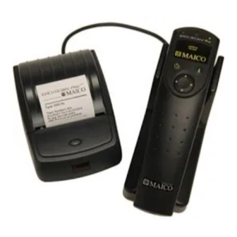
Operating Instructions 2 Getting Started Standard System Parts 2.1 Unpacking the system Standard System Parts: (1) ERO•SCAN Pro Hand-held unit w/ internal probe (1) External OAE•Probe™ or (1) External TympOAE Probe™ Handheld Eartip Kit Cradle (1) Cradle 589-7 589-2 (1) USB cable (1) Box of disposable eartips in assorted sizes (4) AA/UM-3/R6 Alkaline... -
Page 9: Battery Installation
Operating Instructions 2.2 Battery Installation The ERO•SCAN Pro instrument uses 4 AA/UM-3/R6 Alkaline batteries. Open the battery compartment by sliding the battery panel down and install the batteries as indicated on label inside the compartment. Once the batteries are correctly in place, slide the panel back onto its tracks to close the battery compartment. -
Page 10: Internal Probe
Operating Instructions 3.2 Internal Probe The internal probe is located on the underside of the ERO•SCAN Pro instrument. It allows for the measurement of DPOAEs in the range of 1.5 kHz to 6 kHz and TEOAEs in the range of 0.7 kHz to 4 kHz. Note: Tympanometry, acoustic reflex, and high frequency DPOAE measurements are not supported by the internal probe of the ERO•SCAN Pro. - Page 11 Operating Instructions DPOAEs in the range of 1.5 kHz to 12 kHz TEOAEs in the range of 0.7 kHz to 4 kHz. Tymp•OAE Probe™ The Tymp•OAE Probe allows for measurements of: DPOAEs in the range of 1.5 kHz to 12 kHz TEOAEs in the range of 0.7 kHz to 4 kHz Tympanometry with a 226 Hz or 1000 Hz probe tone Acoustic reflexes with 226 Hz probe tone (stimulus options: 0.5, 1, 2, &...
- Page 12 Note: Misalignment of the plug and socket when installing the remote probe can cause damage to the pins in the plug and the pin receptacles in the socket. The plug and socket should be visually inspected prior to each installation of the remote probe. If damage is observed, contact your Special Equipment Distributor or Maico Diagnostics.
-
Page 13: Conducting A Measurement
Operating Instructions 4 Conducting a Measurement 4.1 Quick Start The ERO•SCAN Pro instrument arrives preloaded with default protocols and ready to test. Testing with the external probe can be started with just five easy steps. 1. Turn on the instrument. 2. -
Page 14: Selecting A Protocol Or Protocol Series
Use only the eartips approved for use with the instrument. Contact your local special equipment distributor or Maico Diagnostics for ordering information. The eartips are disposable and should be replaced after each patient. Do not attempt to clean or reuse these eartips. - Page 15 Operating Instructions In addition, when performing acoustic reflex measurements explain to the patient that loud test sounds will occur during the reflex measurement. It is very important that the patient does not move because movements can be perceived as a false compliance change. Ambient Noise Levels in the Testing Environment The ERO•SCAN Pro uses a novel noise-rejection algorithm that permits accurate DPOAE and TEOAE measurements in background noise as high as 65 DB SPL A-weighted (typical office environment).
-
Page 16: Conducting A Measurement
Operating Instructions 4.6 Conducting a measurement After selecting the desired protocol or series, press the right or left arrow button on the navigator or button on the external probe keypad to begin a measurement. Select the left arrow or button to start a left ear test. -
Page 17: Proceeding To The Next Test
Operating Instructions Testing ears with PE tubes To test OAE’s of individuals with PE tubes or middle ear perforations, the AutoStart may need to be disabled. This is accomplished by first inserting the probe with eartip attached into the ear canal. Be sure the fit is deep and secure to obtain a proper seal, To disable AutoStart at the main menu select the ear to be tested by holding down the right or left arrow key for 3 seconds until the green light turns off. -
Page 18: Understanding The Test Results
Operating Instructions 5 Understanding the Test Results 5.1 Understanding the OAE Results Display During OAE testing the results will appear on the screen as the test progresses. The display shows a graph with up to 12 columns. Each f2 frequency (DPOAEs) or frequency band (TEOAEs) is indicated by one column. -
Page 19: Understanding The Tympanometry Results Display
Operating Instructions SNR Graph SNR graph shows signal-to-noise ratio (SNR) for each test frequency. SNR is the difference between the measured emission and measured noise floor. The SNR is shown on the vertical axis so the height of each column represents the SNR for that test frequency. For example, if the column goes to the top of the display then the SNR is 15 dB or greater. -
Page 20: Interpreting The Tympanometric Test Result
Operating Instructions 5.3 Interpreting the Tympanometric test result As a general rule, values for ear canal volume should be between 0.2 and 2.0 ml (children and adults). A variance will be seen within this range depending on the age and ear structure of the person. For example, a 2.0 ml or larger reading in a small child could indicate a perforation in the tympanic membrane, while it may be a normal reading in an adult. - Page 21 Operating Instructions An extremely flaccid tympanic membrane or an ossicular chain discontinuity will yield a very high peak compliance in the presence of normal middle ear pressure and ear canal volume will be normal. A fixation of the ossicular chain, as in otosclerosis, will produce a tympanogram with very low compliance in the presence of normal middle ear air pressure while ear canal volume is normal.
-
Page 22: Understanding The Acoustic Reflex Display & Result
Operating Instructions 5.5 Understanding the Acoustic Reflex Display & Result During the measurement of the acoustic reflex the change of the compliance is represented on the instrument display as shown to the left. The zero-line at the bottom of the graph indicates the measured compliance without a test sound. -
Page 23: Managing Test Results
Operating Instructions 6 Managing Test Results The ERO•SCAN Pro saves one right and one left ear test for each protocol. Once a new test for that ear and protocol is started, the previous results are overwritten. When testing is completed, the results should be printed before a new patient is tested. -
Page 24: Deleting Test Results
Operating Instructions 6.2 Deleting Test Results Deleting a single test delete To delete a single test(s) follow the steps outlined in the previous section (above) and choose from the options provided on the selection menu. Deleting all tests: Show Results To delete all saved tests select from the main menu. -
Page 25: Printing Test Results
Operating Instructions 7 Printing Test Results There are three options for printing tests results from the ERO•SCAN Pro: 1. Quick Print to PDF 2. Quick Print to the default PC printer 3. Fast and portable printing is an option with the thermal paper printer These printing options are explained in this section. -
Page 26: Quick-Print To Pdf Or To The Default Pc Printer
Operating Instructions 7.2 Quick-Print to PDF or to the default PC printer Open the Print Results application double clicking application icon. Place the ERO•SCAN Pro gently in the cradle. Transfer of test data will occur automatically when the instrument is placed in the cradle. This application will print to a PDF file or print to the default PC printer. - Page 27 Operating Instructions The application will give the user the option to add the patient's name to the print out. Enter the patient's name and click [OK]. Click [Cancel] to skip this step if no patient name is desired. You will be prompted to save the file. The software will suggest a file name or you may use a file name of your choice.
- Page 28 Operating Instructions OAE PDF or PC Printout Data table: F2 = the f2 frequency P1 = the sound pressure level of f1 P2 = the sound pressure level of f2 DP = the level of the emission in dB SPL NF = the noise floor in dB SPL SNR = the signal-to-noise ratio (DP level minus the noise floor) P = indicates that the pass criteria has been met for the indicated frequency...
- Page 29 Operating Instructions Tympanometry PDF or PC Printout Data table: Frequency = probe tone frequency (226 or 1,000 Hz) Ear volume = indicates the volume of the external ear canal Gradient = indicates graph width in daPa value (tympanometric width at 50% of the peak) Compliance = displays the peak compliance Peak Pressure = displays the pressure corresponding to peak compliance Graph:...
- Page 30 Operating Instructions Acoustic Reflex PDF or PC Printout Data table: Pressure = pressure compensation to match point of peak compliance from preceding tympanometry measurement Number of stimuli = number of test stimuli included in the protocol (up to four allowed) Minimum for a pass = number of passing stimuli required to meet the compliance change criteria Graphical table:...
- Page 31 Paper rolls must be 57.5 (±0.5) mm wide, 55 mm maximum diameter, and have thermally sensitive coating on the outside. The printer will accept rolls which are coreless or wound on a core. Note: To order more paper, contact your local special instrument distributor or Maico Diagnostics. Procedure for loading paper: Slide the lid release button forward until the lid springs open.
-
Page 32: Connecting The Cradle To The Printer
Operating Instructions After loading, check that the paper is straight and advances properly. Tear off any excess paper by pulling the paper sharply towards you across the serrated tear bar. In the event of a jam or other paper loading problem, release the lit and straighten the paper before closing again. -
Page 33: Printing With The Thermal Paper Printer
Operating Instructions 7.5 Printing with the Thermal Paper Printer Be sure the printer power is on and the button on the cradle is in the printer position. Place the instrument gently in the cradle. A printer icon should appear on the display and the test results should begin printing immediately. - Page 34 Operating Instructions TEOAE Printout To the left is a sample TEOAE printout from the thermal paper printer. The header shows the protocol name in the first line followed by the date/time of the test, test number, instrument serial number, probe serial number, and firmware version. Patient number is indicated or a blank line is provided to write in the name.
- Page 35 Operating Instructions Tympanometry Printout To the left is a sample tympanometry printout from the thermal paper printer. The header shows the protocol name in the first line followed by the date/time of the test, test number, instrument serial number, probe serial number, and firmware version. Patient number is indicated or a blank line is provided to write in the name.
- Page 36 Operating Instructions Acoustic Reflex Printout To the left is a sample acoustic reflex printout from the thermal paper printer. The header shows the protocol name in the first line followed by the date/time of the test, test number, instrument serial number, probe serial number, and firmware version.
-
Page 37: Set Up
Operating Instructions 8 Set Up Set Up Set Up To enter the menu, scroll down the main menu to select by pressing the right arrow button. Scroll through the set up menu options using the up and down arrow buttons on the control panel. -
Page 38: Display Contrast
Operating Instructions 8.3 Display Contrast Display To change the contrast of the display, select from the set up menu. Use the up and down arrows to adjust the contrast. When done adjusting the contrast press the right arrow button to Save and exit. -
Page 39: Oae Minimums
Operating Instructions 8.6 OAE Minimums This setting allows the user to select if minimum amplitude values Use Minimums will be used as part of the pass/refer criterion. If , a result is not considered a pass unless the OAE amplitude is equal to or greater than the minimum value set in the protocol. -
Page 40: Sounds
Operating Instructions To change this setting, select Patients from the Set Up menu. Using the up and down arrow No Patients Numbered Patients buttons on the control panel select and then press the right arrow select button to and exit. -
Page 41: Norms
Operating Instructions 8.10 Norms When viewing DPOAE results using the DP/TE-Gram option (section 8.9), the user may optionally show the Boys Town normative data on the instrument display. The user can select to show the 95 to 5 range or the 90 to 10 range. -
Page 42: Customizing Protocols And Series
Operating Instructions 9 Customizing Protocols and Series Users of any instrument type can create series of protocols. Users of diagnostic instruments can also Print Results customize individual protocols. The software application is used to create and manage custom protocols and series. This section will explain how to customize protocols and series. For software installation instructions see Appendix A. - Page 43 Operating Instructions The Protocols dialog to the left shows the protocol files stored on the computer. This list can consist of protocols loaded into the instrument and protocol files which are currently located only on the computer. Manufacturer default protocols appear in blue font. User created or modified protocols appear in black font.
- Page 44 Operating Instructions Creating a DPOAE Protocol Create New To create a new protocol file, click the button located on the right panel of the protocol window. A new dialog will appear, select DPOAE Protocol The New DPOAE Protocol dialog above shows the window for creating or modifying a DPOAE Protocol. Protocol Name: the text entered into the Protocol Name field is what will appear in the instrument when the protocol is loaded.
- Page 45 Operating Instructions SNR to Pass: defines the minimum SNR required for that frequency to be considered a passing frequency. SNR to Pass is adjustable between 3 and 10 dB Minimum DP: defines the minimum DPOAE (signal) amplitude required for that frequency to be considered a passing frequency.
- Page 46 Operating Instructions Above is the TEOAE protocol editing window. Protocol Name: the text entered into the Protocol Name field is what will appear in the instrument when the protocol is loaded. This should be kept to approximately 14-16 characters in length so that the full protocol name can be viewed on the instrument display.
- Page 47 Operating Instructions Creating a Tympanometry Protocol Create New To create a new protocol file, click the button located on the right panel of the protocol window. A new dialog will appear, select Tympanometry Protocol To the left is the Tympanometry protocol editing window. Protocol Name: the text entered into the Protocol Name field is what will appear in the instrument when the protocol is loaded.
- Page 48 Operating Instructions Creating an Acoustic Reflex Protocol Above is the Acoustic Reflex protocol editing window. Protocol Name: the text entered into the Protocol Name field is what will appear in the instrument when the protocol is loaded. This should be kept to approximately 14-16 characters in length so that the full protocol name can be viewed on the instrument display.
- Page 49 Operating Instructions Renaming a Protocol File The protocol name that appears in the instrument is a parameter established within the protocol file. The Windows file name for the protocol can and may be different than the protocol name. For ease of managing protocols you may want to rename protocol files so that the protocol name and file name Rename match.
-
Page 50: Managing Protocols In The Instrument
Operating Instructions 9.2 Managing Protocols in the Instrument To load new or modified protocols into the instrument or to remove unused protocols from the instrument, click on the button located in the upper right corner of the main window Manage Protocols and Protocol Series This dialog allows the user to manage the protocols and series in the instrument. -
Page 51: Creating Series
Operating Instructions Load Protocols To load a protocol into the instrument, click the Load button located in the right panel of the Protocols in Instrument window. When prompted (Figure 80) select the appropriate directory for the protocol being loaded. Factory = manufacturer created protocols User = user modified or created protocols Open Select the protocol or protocols you wish to load and click... - Page 52 Operating Instructions Step 1: Type the series name into the text box provided. Series names should be kept to approximately 12 characters in length to ensure the full protocol name will display on the instrument. Available Protocols Step 2: From the list of on the left of the window, select the first protocol for the series and then click Step 3: You will be prompted to determine when the testing sequence should proceed to the next...
-
Page 53: Troubleshooting
External probe has not been Check connector, power off the instrument detected. and then power on again. Equipment malfunction. Contact your special instrument distributor or Maico Diagnostics. Protocols or series are missing external probe which Turn off the instrument, connect the probe... -
Page 54: Care And Maintenance
Do not immerse the instrument in fluids or attempt to sterilize the instrument or any of its accessories 11.2 Maintenance & Calibration This instrument should be calibrated annually by your special equipment distributor or by Maico Diagnostics. Beyond that, it requires no regular maintenance other than routine cleaning and battery replacement. The probe tip requires replacement only when it becomes clogged. -
Page 55: Important Safety Precautions
In the event of a critical system failure, the message shown to the left will be displayed. Discontinue use of the instrument and contact your Special Equipment Distributor or contact Maico Diagnostics by phone at (888) 941-4201 or by fax at (952) 903-4100. -
Page 56: System Specifications
Operating Instructions 13 System Specifications DPOAE SYSTEM PRIMARY TONES: Frequency: F2 from 1.5 kHz to 12 kHz Intensity: Up to 6 kHz: 40/40 to 70/60 dB SPL Over 6 kHz: 40/40 to 65/55 dB SPL MIC SYSTEM NOISE: <=-20 dB SPL @ 2 kHz (1 Hz Bandwidth) ARTIFACT: <-20 dB SPL @ 2F1-F2 Frequency F1/F2 RATIO:... -
Page 57: Warranty
Changes in the product not approved by Maico Diagnostics shall void this warranty. Maico Diagnostics shall not be liable for any indirect, special or consequential damages, even if notice has been given of the possibility of such damages. -
Page 58: Appendix A: Ero-Scan Pro Software Installation Instructions
Operating Instructions Appendix A: ERO-SCAN Pro Software Installation Instructions 1 Application Installation To begin installation double click on the installer file: EroscanPro_installer_user_p-120508.exe Then follow the steps as shown below (from left to right by row):... - Page 59 Operating Instructions If the installed cradle driver is an older version, it will be uninstalled and the new driver will be installed.
- Page 60 Operating Instructions 2 Setting PC Software Preferences PC software preferences can be set using the following in the Preferences menu Printing Test Results The first time test data is transferred to the application you will be prompted to establish your printing preferences.
- Page 61 Operating Instructions Report Header Users can optionally choose to customize the printed report header to include practice information and/or logo as desired. Select Preferences > Report Header For Text only in the report header, enter the desired information into the four text lines available in the Report Header dialog.
- Page 62 Operating Instructions Boys Town Norms Template Users may optionally show the Boys Town Norms template on the DP-Gram of the PDF or printed test report by selecting that option with Preferences > Show Boys Town Norms Template with DP Graphs. The Boys Town Norms template is explained in the following window.
-
Page 63: Appendix B: Default Test Protocols And Protocol Series
Operating Instructions Appendix B: Default Test Protocols and Protocol Series Screener Protocol Name Protocols Included Combo Screening (DP) Tymp 226 Hz > DP QuickScreen Screening (TE) Tymp 226 Hz > TE QuickScreen Infant (DP) DP QuickScreen > Tymp 1000 Hz Infant (TE) TE QuickScreen >... -
Page 64: Appendix C: Test Technique And Sequence
Operating Instructions Appendix C: Test Technique and Sequence Test Technique As with any other OAE or Tympanometry instrument, there is a technique to learn when using the ERO•SCAN Pro instrument, especially for infants and young children. Experience with existing systems suggests that it may take up to 3 months to become completely proficient at selecting the proper eartip and positioning the probe. - Page 65 Operating Instructions TEOAE The calibration phase automatically measures the peak pressure obtained from a sequence of clicks and calculates the voltage required to obtain the target peak pressure. If the desired peak pressure cannot be obtained, the unit will use the maximum voltage. The test phase consists of measuring the response obtained from repeated sequences of clicks applied to the receivers.
-
Page 66: Appendix D: Pass/Refer Criteria
Operating Instructions Appendix D: Pass/Refer Criteria Pass/Refer Criteria for DPOAE The decision that a DPOAE exists is based on detecting a signal whose level is significantly above the background noise level. This requires a statistical decision, since the random noise level in the DPOAE filter channel can be expected to exceed the average of the random noise levels in the four adjacent filter channels —... - Page 67 Operating Instructions The improved operation in noise with the new algorithm was so substantial that we conducted a complete replica of our original validation tests in "fully impaired ear" cavities and were able to verify that no increase in false negatives (false passes) was introduced. Under no test conditions was any such degradation uncovered.
- Page 68 ERO-SCAN Pro to result in comparable pass/refer results to existing clinical standard equipment (Grason-Stadler, 2005; Interacoustics, 2007; Interacoustics, 2011; Maico, 2005; and Maico, 2011). A correct interpretation of the measuring results can only follow in connection with the tympanogram, the graphic reflex display and other actual data.
-
Page 69: Appendix E: High Frequency Measurements
Operating Instructions Appendix E: High Frequency Measurements High Frequency DPOAE Measurements In healthy young ears, distortion product otoacoustic emissions are normally present in the 6-12 kHz region. Figure 1 shows ERO•SCAN measurements on a 12 year old. Figure 2 shows ERO•SCAN measurements obtained on an adult male in his 60s. - Page 70 Operating Instructions Important Considerations When Monitoring Typical of all DPOAE and TEOAE measurements, the lower limit of measurement is determined by noise, most of which has a Gaussian distribution. In the absence of an emission, both the signal and reference channels contain nothing but noise.
- Page 71 Operating Instructions Instructions for Averaging Results For monitoring purposes, it is the DP level itself that should be averaged. The DP level indicates the health of the outer hair cells and the middle ear, when testing in relatively quiet conditions. The SNR is the measurement of choice in screening, where varying noise levels are present.
-
Page 72: References
Jerger, J.F. (1970). Clinical experience with impedence audiometry. 92(4), 311-324. Maico Diagnostics (2005). Operating Manual: MI 24, MI 24h Maico Diagnostics (2011). Operating Manual: easyTymp Siegel, J.H. Hirohata, E.T. (1994). Sound calibration and distortion product otoacoustic emissions at high frequencies. - Page 73 Specifications subject to change without notice. MAICO Diagnostics 10393 West 70 Street Eden Prairie, MN 55344 Tel.: 888.941.4201 Fax: 952.278.4481 E-mail: info@maico-diagnostics.com Internet: www.maico-diagnostics.com...
- Page 74 1162-0802 Rev E 05/12...
Need help?
Do you have a question about the Ero Scan Pro and is the answer not in the manual?
Questions and answers