Maico MA 42 Service Manual
Hide thumbs
Also See for MA 42:
- Operation manual (82 pages) ,
- Operating instructions manual (64 pages) ,
- Quick manual (2 pages)
Table of Contents
Advertisement
Advertisement
Table of Contents

Related Manuals for Maico MA 42


Summary of Contents for Maico MA 42
- Page 1 MA 42 Service Manual...
-
Page 2: Table Of Contents
1.1 About this Manual ..................... 2 1.2 About warnings and cautions ................... 2 1.3 General information ....................2 MA 42 Control Panel ....................3 2.1 Display and Control Panel ..................3 2.2 Connections ......................10 2.3 Pin Assigment ......................11 2.4 Setup in a Sound Booth.................. -
Page 3: Introduction
The performance and specifications of our products can only be guaranteed if technical maintenance is conducted routinely every year. Technical maintenance should be carried out by qualified personnel authorized by MAICO. We refer to the thoroughly described calibration procedure in this service manual. -
Page 4: Ma 42 Control Panel
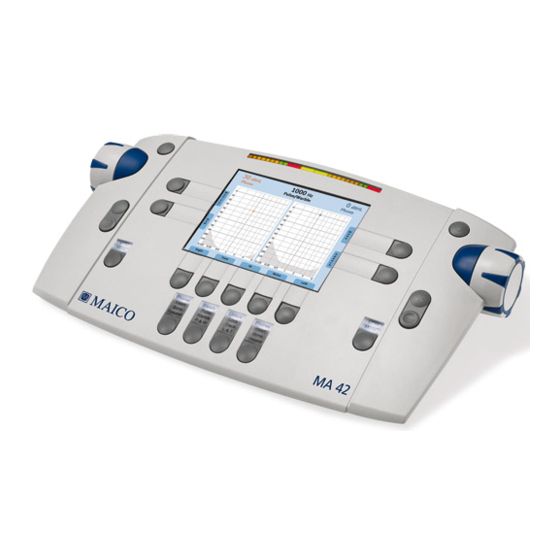
MA 42 Control Panel 2.1 Display and Control Panel The main functions of the MA 42 are directly accessible by using the function keys which are located around the display. Some of the function keys behave differently depending on how long they are pressed: e.g. - Page 5 Service Manual MA 42 Figure 2 Table 1 Operating Elements No. Key Information Control Dial to select (hearing level, test, setting). to present/interrupt signal or noise (hearing level) or confirm selection (test, setting) S keys to store single results. Press for 2 s to store a No Response result.
- Page 6 Service Manual MA 42 Table 2 Data Management Symbol Select Function Quick Select to print test report to the default printer. Advanced to print test report to the selected printer ( : PDF, Select thermal printer). Quick Select to delete all stored results and create a new session.
- Page 7 Service Manual MA 42 Table 4 Test Setup Symbol Select Function to change ears (left ↔ right channel). Quick Select to select ear for the left OR right channel. Selection for the other channel stays the same. Advanced Select NOTE: This function can be useful if you want to apply Signal (Tone or Speech Input) AND Noise to the same ear.
- Page 8 Service Manual MA 42 Symbol Select Function Freiburger Speech Test: Numbers Words Quick to select the test type. Select Quick to change Wave Input and Noise (left ↔ right channel). Select Advanced to select Wave Input for binaural presentation. Select...
- Page 9 Service Manual MA 42 Table 6 STIM/TALK Key and STIM/Monitor Key Select Function Quick Select STIM: to switch between Presenter and Interrupter mode. Talk: to open the Communication widget (Figure 5) STIM Talk Figure 4 Talk Forward: Allows tester to provide instruction to the...
- Page 10 Service Manual MA 42 Select Function Speech Test: Monitor: to open the Monitor/Input Calibration widget (Figure 7). Figure 6 Monitor: Allows you to hear the Speech Input and Noise stimuli through the internal speaker or monitor headset via an optional talk back microphone. Increase/decrease the...
-
Page 11: Connections
Service Manual MA 42 2.2 Connections In order to ensure that the device works properly, it has to be checked and calibrated at least once every twelve months. Figure 7 Table 7 Connections on Backside CONNECTIONS Connection socket Specification On/Off... -
Page 12: Pin Assigment
Service Manual MA 42 2.3 Pin Assigment Pin I Pin O Socket No. Connector (Inner) (Outer) 12 V Ground DC socket Socket No. 1. +5 VDC 2. Data - 3. Data + 4. Ground 1. +5 VDC 2. Data - 3. -
Page 13: Setup In A Sound Booth
This will lead to severe device failure. Installation should be carried out by an authorized MAICO service technician only. Check before use that the installation is correct (e.g. after cleaning). -
Page 14: Establishing A Connection To A Pc, Printer Or An External Audio Device
Ensure that your PC is adequately protected against cyber-attacks. To transfer data to a PC, establishing a PC connection via USB is required. If the MA 42 is used with office equipment that is not a medical device itself (see Table 8PC Connection 1), make sure to establish the PC connection in one of the following ways (see, PC Connection 2, 3 or 4). -
Page 15: Maintenance, Cleaning And Disinfection
Recommendations for cleaning and disinfection of MAICO device presented in this document are not intended to replace or contradict policies in effect or procedures required for infection control at the facility. -
Page 16: Service And Calibration
MAICO. Before any attempt is made to calibrate MA 42, it must have been powered on for 3-5 minutes in an ambient temperature that is both stable and comfortable. -
Page 17: Software Calibration
Service Manual MA 42 4.2 Software Calibration For the software calibration of the MA42 the following is required. 1. MA42 to a PC with a USB 2.0 cable. 2. MA42 Calibration Tool. 3. Service Code available for approved service partners 4.2.1 Installation of Calibration Tool... - Page 18 Service Manual MA 42 Step 2a: Chose the folder where you want the Cal Software to be saved or just proceed with the default folder (recommended) with Next. or Step 2b: If the SW is already installed you can also repair or remove the Calibration Tool from the PC, if necessary: D-0125965 Rev.
- Page 19 Service Manual MA 42 Step 3: Click on Install to start the Installation: Step 4: Depending on your PC configuration you might get User Account Control request. To continue confirm with yes: There after the installation process will start. D-0125965 Rev. D...
- Page 20 Service Manual MA 42 During the installation process a statusbar is visible until the process is complete. Step 5: Once the Finish button in the Setup Wizard becomes active press it to exit the setup process. • IEC 60318-5, Electroacoustics – Simulators of human head and ear - Part 5: 2 cm³...
- Page 21 Service Manual MA 42 For the software calibration a PC connection is required. 4.2.2 Prepare the MA42 Device for Calibration 1. Connect all requested parts including USB and Power Supply. 2. Press the button on the back to power on the device.
- Page 22 Service Manual MA 42 6. Login in as service user as follows. 7. Enter Password using the onboard keyboard in conjunction with the dials and confirm your choice with one of the buttons. Close keyboard with 8. When the service access was successful the following screen will apear. Close confirmation message OK with 9.
- Page 23 Service Manual MA 42 11. If Device Calibration does not show Ready, press Start: 12. Start button turns to Ready and appears disabled. ✓ Device is ready for calibration. 4.2.3 Initate the Calibration Tool 1. Activate the Calibration Tool on your PC.
- Page 24 Service Manual MA 42 3. Below the Main Tab the following tabs can be selected: Standards Setup, Transducer Setup, Free Field Setup, Custom Max, Transducer Calibration as well as Test option can be accessed. 4. Select the required Standards Select the Ton standard in the drop...
- Page 25 Service Manual MA 42 6. Select the Free Field Setup Tab to select the type of output as well as Speaker Setup. Select the Output Type Select the Speaker setup 7. Select the Custom Max Tab if custom maximum values for Free Field are required.
- Page 26 Service Manual MA 42 9. Under the Test Tab the following tabs can be selected: Attenuator Test, Patient response Test, Diode Test as well as setting the Real time clock under the Service Tab. For the Attenuator linearity check select the Attenuator Tab.
- Page 27 Service Manual MA 42 12. Select Service Tab to set the Real time clock. 13. After the calibration and all the test have been completed press Save & Close to exit the calibration Software. 4.2.4 How to add dealer information (1) Log in as Service as mention in section 4.2.2...
- Page 28 Service Manual MA 42 (4) Add dealer information by using on-screen keyboard with NOTE: Dealer information will be available under Service menue for end user, so that end user can easily contact their service partner or distributor. D-0125965 Rev. D...
-
Page 29: Disassembly
Service Manual MA 42 Disassembly Remove the screws from the lower cabinet. Cut the cable ties and cerefully remove glue from cable disconnect the cable. Disconnect the second cable. Open the device D-0125965 Rev. D 18/05/2022... - Page 30 Service Manual MA 42 Remove glue disconnect cable from the upper case. Remove left and right rotary button Remove screws now the cover lid for the bearing housing can be opened. Bearings can now be removed Disassambled axle for the bearings and the magnet.
- Page 31 Service Manual MA 42 Put out encoder PCA Remove screws from the impeller D-0125965 Rev. D 18/05/2022...
- Page 32 Service Manual MA 42 Take out the bearing cover lid and remove the bearing. Take out the impeller D-0125965 Rev. D 18/05/2022...
- Page 33 Service Manual MA 42 Remove glue disconnect the cable of the microphone. Remove screws from the PCA. Take out the PCA. Remove left, right and center keypads D-0125965 Rev. D 18/05/2022...
- Page 34 Service Manual MA 42 Take out light guides D-0125965 Rev. D 18/05/2022...
- Page 35 Service Manual MA 42 Take out the display with display frame from the upper cabinet. Disassamble the display from the display frame. Take out the display cover (PMMA). D-0125965 Rev. D 18/05/2022...
- Page 36 Service Manual MA 42 Disconnect speaker cable. Remove 4 screws and take out the speaker. D-0125965 Rev. D 18/05/2022...
- Page 37 Service Manual MA 42 Disassamble screws and screw fittings from the PCA. D-0125965 Rev. D 18/05/2022...
-
Page 38: Technical Data
General Information About Specifications The performance and specifications of the device can only be guaranteed if it is subject to technical maintenance at least once every 12 months. MAICO Diagnostics puts diagrams and service manuals at the disposal of authorized service companies. STANDARDS IEC 60601-1:2005 (Third Edition) + CORR. - Page 39 External Devices Audio device, USB Thermal Printer Supported Printers HPRT HM-E300 USB: the system cannot be operated from a PC. PC Connection Using MAICO Sessions together with the OtoAccess Database, Noah or a Practice Management Software via BDT/GDT-interface (only Germany, Austria Switzerland), data can be transferred and saved on the PC.
- Page 40 Service Manual MA 42 AUDIOMETRY Patient Response One push button Switch Patient Talk Forward communication Masking Signals Narrow band noise masking for tone: IEC 60645-1 2012, 5/12 Octave filter with the same center frequency resolution as pure tone White Noise: 80 Hz to 20 kHz measured with constant bandwidth...
- Page 41 Service Manual MA 42 AUDIOMETRY Tone Audiometry Tone Tests HL, MCL, UCL, Aided Special Tests High Frequency Audiometry Pure Tone Stenger SISI Test (Automatic test: 5, 4, 3, 2, 1 dB Increment of 250 ms every 5 s, Response Window = 1500 ms from start of increment)
- Page 42 Service Manual MA 42 AUDIOMETRY Speech Signals Microphone (Mic), Wave or external audio device (AUX) Speech Level AC: -10 dB HL to 100 dB HL BC: -10 dB HL to 60 dB HL Insert phones: -10 dB HL to 95 dB HL...
-
Page 43: Calibration Values And Maximum Levels
Service Manual MA 42 6.2 Calibration Values and Maximum Levels Calibration Values and Max Levels: Headphone DD45 Coupler IEC 60318-3, PTB Report 2009, DTU Report 2010 Tone/Ped. Tone/Ped. Sound Fre- Noise Noise Attenuation quen- RETSPL Max Level RETSPL [dB] Max Level... - Page 44 Service Manual MA 42 Calibration Values and Max Levels: Headphone DD65 V2 Coupler IEC 60318-1, PTB Report 2018, AAU Report 2018 Tone/Ped. Tone/Ped. Sound Fre- Noise Noise RETSPL Max NBN Attenuation quency RETSPL dB re Max Level [dB HL] [dB]...
- Page 45 Service Manual MA 42 Calibration Values and Max Levels: Headphone HDA 300 Coupler IEC 60318-1 with adapter, ANSI 3.6 and ISO 389-8/ISO 389-5 /Ped. /Ped. Tone Tone SOUND Fre- Noise Noise ATTENUA- quency RETSPL dB Max Level TION [dB] [dB]...
- Page 46 Service Manual MA 42 Calibration Values and Max Levels: Headphone DD450 Coupler IEC 60318-1 with adapter, ANSI 3.6 and ISO 389-8/ISO 389-5 /Ped. /Ped. Tone Tone SOUND Fre- Noise Noise ATTENUA- quency RETSPL Max Level TION [dB] [dB] Max Level...
- Page 47 Service Manual MA 42 Calibration Values and Max Levels: Headphone HOLMCO 9501 Coupler IEC 60318-1, ANSI 3.6 and ISO 389-8 Tone/Ped. Tone/Ped. Sound Noise Noise Frequency RETSPL Max NBN Attenuation [dB] RETSPL Max Level [Hz] dB re [dB HL] ISO 8253-1 dB re 20µPa...
- Page 48 Service Manual MA 42 Calibration values and Max Levels: Insert Phones IP30 Coupler (2cc) IEC 60318-5 made in accordance to ISO 389-2, ANSI S3.6 Tone/Ped. Tone/Ped. Sound Noise Frequency Noise Max NBN Attenuation RETSPL RETSPL Max Level [dB] [Hz] [dB HL] dB re 20µPa...
- Page 49 Service Manual MA 42 Calibration values and Max Levels: Bone Conductor B71 Coupler IEC 60318-6, mastoid placement, ISO 389-3, ANSI S3.6 Tone/Ped. Tone/Ped. Noise Frequency Noise Max NBN Air Radiation RETSPL RETSPL Max Level [dB] [Hz] [dB HL] dB re 20µPa dB re 20µPa...
- Page 50 Service Manual MA 42 Calibration values and Max Levels: Bone Conductor B81 Coupler IEC 60318-6, mastoid placement, ISO 389-3, ANSI S3.6 Tone/Ped. Tone/Ped. Noise Frequency Noise RETSPL Air Radiation RETSPL Max Level [dB] [Hz] dB re [dB HL] dB re 20µPa 20µPa...
- Page 51 Service Manual MA 42 Calibration values and Max Levels: Bone Conductor BKH10 Coupler IEC 60318-6, mastoid placement, ISO 389-3, ANSI S3.6 Tone/Ped. Tone/Ped. Noise Frequency Noise RETSPL Air Radiation RETSPL Max Level [dB] [Hz] dB re [dB HL] dB re 20µPa 20µPa...
- Page 52 Service Manual MA 42 Calibration values: Sound field Reference equivalent threshold sound pressure level and maximum hearing levels For SP90A, SP90, SP85A and AP70FF Amplifier ANSI S3.6:2010 Sound Field max. SPL For Sound Field max. HL ISO 389-7:2005 subtract the selected...
-
Page 53: Spare Parts
Operation Manual MA 42 Spare Parts Part No. Description Picture 8522049 Lower Cabinet Kit (INT/JP) 8513647 Lower Shell Cabinet bottom 8513990 Rear overlay EN 8002378 Adjustable feet cradle 8003041 M3x8mm torx pan head Screw 8526915 Dial Support Kit Total QTY in device: 2... - Page 54 Operation Manual MA 42 8526916 Encoder Support Kit Total QTY in device: 2 8513649 Axle for magnet 8515934 Magnet 8003675 Ball Bearing 8513644 Bearing for magnet support 8003043 PT2x8mm torx flange head screw 8522413 Keypad Kit 8512798 Keypad left 8512796...
- Page 55 Operation Manual MA 42 8522419 Light Guides Kit JP 8107001 Light guide left JP (printed) 8521766 Light guide right JP (printed) 8107003 Light guide center JP (printed) 8522962 PCA Keyboard Kit (tested) 8506436 PCA Keyboard 8522961 PCA Mainboard Kit (tested, incl. FW)
- Page 56 Operation Manual MA 42 Part No. Description Comment Spare Parts (no kits) 8527479 Upper Shell (Top Part) 8520911 Dial Assembly Total QTY in device: 2 8511928 PCA Encoder Total QTY in device: 2 8527482 Rotator insert A 8527483 Rotator insert B...
- Page 57 Operation Manual MA 42 8519801 Display support 8002378 Rubber foot (adjustable feet) Total QTY in device: 4 8108814 Microphone cable 8515925 Speaker Part No. Description Comment Additional Parts (no kits) 8004140 Flex cable 8003518 Cable tie 8003518 Push mount tie...
- Page 58 Operation Manual MA 42 8003041 M3x8mm torx pan head Screw Total QTY in device: 8 8003043 PT2x8mm torx flange head screw Total QTY in device: 8003186 PT2.5x8 torx pan head screw Total QTY indevice: 12 D-0125965 Rev. D 18/05/2022...
-
Page 59: History
Operation Manual MA 42 History Version Modified Major Differences Date Initial draft 29.03.2021 Update calibration values and spare parts 09.04.2021 Update section 4.2.2 18.05.2022 New spare part Numbers added and New calibration tables added D-0125965 Rev. D 18/05/2022...
Need help?
Do you have a question about the MA 42 and is the answer not in the manual?
Questions and answers