Table of Contents
Advertisement
Quick Links
Advertisement
Table of Contents

Subscribe to Our Youtube Channel
Related Manuals for Upvel UP-308FEW


Summary of Contents for Upvel UP-308FEW
-
Page 2: Table Of Contents
UP-308FEW / UP-316FEW Table of Contents Product Overview ........................4 Package Contents ....................... 4 Features ..........................5 External Components Description ..................6 LED Description ........................7 Installation ..........................8 Installation Site Requirements ..................8 Desktop installation ......................8 Rack mounting ........................8 Power connection ....................... - Page 3 UP-308FEW / UP-316FEW VLAN Setting ........................24 VLAN Mode ........................24 VLAN Member ........................ 26 Multi to 1 Setting ......................29 Per Port Counter ....................... 30 QoS Setting ........................31 Priority mode ........................31 Class of Service ......................32 Security ..........................34 MAC Address Binding ....................
-
Page 4: Product Overview
UP-308FEW / UP-316FEW Product Overview UP-308FEW UP-316FEW Package Contents • 8-/16-port PoE+ Switch • Power cord • Rack mounting kit: L-brackets (2 pcs) and screws (8 pcs) • Rubber feet (4 pcs) • Quick Installation Guide • Warranty Certificate Note. If any of the listed items are damaged or missing, please contact your distributor. -
Page 5: Features
30 watts of power on each port as required per 802.3at. The total available power regiment is limited at 140 watts for UP-308FEW and 260 watts for UP-316FEW. Electrical power is transmitted along with data in one single cable allowing you to expand your network where there are no power lines or outlets For non-PoE devices the power feed is auto-blocked and only data is transmitted. -
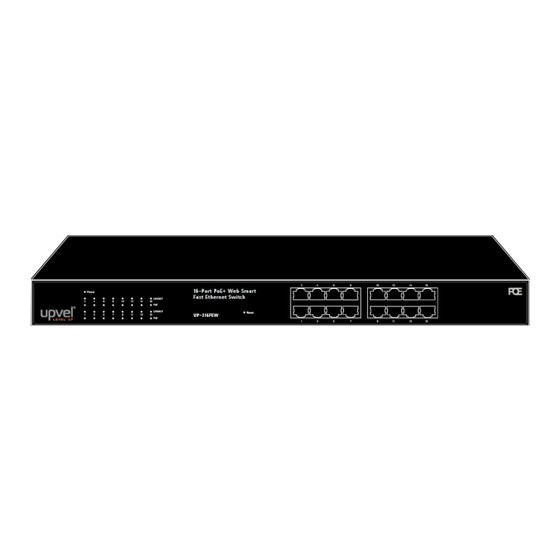
Page 6: External Components Description
UP-308FEW / UP-316FEW External Components Description Front panel of UP-308FEW RJ-45 PoE+ 10/100 Mbps ports Power Power LED indicator LNK/ACT 1~8 Ethernet connection/activity LEDs of the corresponding ports PoE 1~8 PoE-enabled device connection LEDs of the corresponding ports Reset Factory Defaults Restore button... -
Page 7: Led Description
UP-308FEW / UP-316FEW LED Description Indicator Color Status Description Power on Power Green Power off Connection is established LNK/ACT Green Connection is not established Flashing Data is being transmitted PoE-enabled device is detected Green Flashing The power is insufficient for operation of PoE device... -
Page 8: Installation
UP-308FEW / UP-316FEW Installation Installation Site Requirements Ensure that the location where you plan to install the switch meets the following requirements: • Air temperature and humidity should be within the specified ranges (see technical specifications on pp. 52, 53) •... -
Page 9: Connecting To End Nodes
UP-308FEW / UP-316FEW Connecting to end nodes Use standard Cat.5/5e twisted pair cable (UTP/STP) to connect the switch to end nodes. Switch ports will automatically adjust to the characteristics (MDI/MDI-X, speed, duplex) of the connected devices. After connecting all the devices required, you can configure various features of the switch using its Web management interface. -
Page 10: Accessing The Switch Web Management Gui
UP-308FEW / UP-316FEW Accessing the switch Web management GUI 1. Connect the switch to the computer, which you will use for configuring the switch. 2. Assign a Static IP address to the computer's network adapter in the subnet of 192.168.10.x (e.g. 192.168.10.100) and a subnet mask of 255.255.255.0 3. -
Page 11: Switch Configuration
UP-308FEW / UP-316FEW Switch configuration Administrator Authentication Configuration This page allows to change the current username and password that are used to login the switch web management interface. Enter new Username and/or Password and then click Update to confirm changes. The “Update Successfully”... -
Page 12: System Ip Configuration
UP-308FEW / UP-316FEW System IP Configuration This page shows the current IP configuration of the switch including the IP Address, Subnet Mask, Gateway and IP Configuration type (Static or DHCP). You can change the IP settings of the switch according to your network configuration. If you choose DHCP in the IP Configure field, the switch will act as DHCP client and will get the IP address from the network DHCP server. -
Page 13: System Status
UP-308FEW / UP-316FEW System Status This page shows the information about the switch: MAC address, firmware version and number of ports. The Comment field allows to set the switch name so that it could be easily identified in your network. -
Page 14: Firmware Update
UP-308FEW / UP-316FEW Firmware Update This page allows to update the firmware of the switch. To execute the firmware update, you should enter the password in both Password and Reconfirm fields, and then click Update. The pop-up warning window will appear for making sure you want to proceed the firmware updating procedure. -
Page 15: Poe
UP-308FEW / UP-316FEW PoE Status This page contains information about PoE functionality and allows to set the maximum available power of all ports. System operation status Shows the PoE function status (On / Off). Indicates the total power consumption of PoE devices Main Power Consumption connected to the switch. -
Page 16: Poe Setting
UP-308FEW / UP-316FEW PoE Setting This page allows to configure the PoE function for each port. Status Enable/disable PoE for selected ports. Select AF or AT mode according to the PoE standard (802.3af or 802.3at) Mode supported by the device connected to the port. The port provides up to 15.4 watts in AF mode and up to 30 watts in AT mode. -
Page 17: Poe Power Delay
UP-308FEW / UP-316FEW PoE Power Delay This page allows to set a delay before supplying power to the ports once the switch is powered on. This may be useful if there are multiple high-power PoE devices connected to the switch (e.g. -
Page 18: Poe Scheduling
UP-308FEW / UP-316FEW PoE Scheduling The PoE scheduling feature provides an hourly/weekly scheduling mechanism for advanced power control. You can configure each PoE port to be ON or OFF on an hourly basis for energy conservation and provision power only when needed. -
Page 19: Port Management
UP-308FEW / UP-316FEW Port Management Port Configuration This page allows to configure the operating mode of each physical port. Auto-Negotiation Enable / Disable. If set to Enable, the Speed, Duplex Auto mode and Flow Control are negotiated automatically. If set to Disable, you have to assign these parameters manually. - Page 20 UP-308FEW / UP-316FEW Select Port No.: select the ports to which you want to apply the settings. Click Update for the settings to take effect. The settings will be reflected in the status table. Current Status: displays the status of each port.
-
Page 21: Port Mirroring
UP-308FEW / UP-316FEW Port Mirroring Port mirroring is used to send a copy of packets from one switch port (or an entire VLAN) to a network monitoring connection on another switch port. This feature allows to analyze and debug data and diagnose errors on a network, thus helps network administrators keep a close eye on network performance and alerts them when problems occur. -
Page 22: Bandwidth Control
UP-308FEW / UP-316FEW Bandwidth Control This page allows to set the maximum transmit/receive rate for each port. Select the port number you want to configure, enter the desired values of Tx (transmit) and Rx (receive) rates, select high or low speed base and click Update to make the settings effective. -
Page 23: Broadcast Storm Control
UP-308FEW / UP-316FEW Broadcast Storm Control The broadcast storm control is used to block excessive broadcast packets. If the number of broadcast packets exceeds the defined threshold during one time unit, all excessive broadcast packets will be dropped. The time unit is 500 μs for 100 Mbps link speed and 5000 μs for 10 Mbps link speed. -
Page 24: Vlan Setting
UP-308FEW / UP-316FEW VLAN Setting A Virtual LAN (VLAN) is a logical grouping of network devices where the members can be on different physical segments. It allows to isolate network traffic, so only the members of the same VLAN will receive traffic from the ones of the same VLAN. Basically, creating a VLAN from a switch is logically equivalent to reconnecting a group of network devices to another Layer 2 switch. - Page 25 UP-308FEW / UP-316FEW After having switched to Tag Based VLAN Mode, the screen changes. On this screen, you can define and configure Uplink and Downlink ports. These are important since here the handover between the switches of your network takes place.
-
Page 26: Vlan Member
UP-308FEW / UP-316FEW VLAN Member This page is used to assign ports as members of VLAN groups. The screen here looks different whether you run Tag Based or Port Based Mode. VLAN Member Setting in Port Based Mode On the top screen, select the port you want to configure, click Read, and then select or deselect the ports that are on the same VLAN group. - Page 27 UP-308FEW / UP-316FEW VLAN Member Setting in Tag Based Mode In Tag-based Mode, you need to define and configure VLAN groups. Assign the VLAN ID, select the VLAN member ports, assign the PVID and check the configuration result. In the following figure, ports 1~7 are in the same VLAN group.
- Page 28 UP-308FEW / UP-316FEW • VID Source Port This table allows to set PVID of the port. Select the port number while you add VLAN and select VLAN member ports. The selected ports’ PVID will be the VID you typed. Please note that one port can have only one PVID. While one port joins multiple VLAN groups, the PVID is important to identify where the incoming traffic will be forwarded to.
-
Page 29: Multi To 1 Setting
UP-308FEW / UP-316FEW Multi to 1 Setting Multi-to-1 VLAN is used on CPE side of Ethernet-to-the-Home and is exclusive to VLAN setting on “VLAN member setting”. When the VLAN member setting is updated, Multi-to-1 setting will be void and vice versa. The "disable port" means the port, which will be excluded in this setting. -
Page 30: Per Port Counter
UP-308FEW / UP-316FEW Per Port Counter This page shows packet statistics for each port. Statistics are grouped into the following categories: • Receive Packet & Transmit Packet: This category shows both the received packets count (excluding the incorrect packets) and the transmitted packets count. -
Page 31: Qos Setting
UP-308FEW / UP-316FEW QoS Setting Here you can configure QoS priority mode and CoS (Class of Service). QoS (Quality of Service) refers to mechanisms in the network software that make the actual determination of which packets have priority. CoS refers to feature sets, or groups of services, that are assigned to users based on company policy. -
Page 32: Class Of Service
UP-308FEW / UP-316FEW Class of Service There are four Class of Service schemes provided: TCP/UDP port, IP ToS/DS, 802.1p and Physical port. The switch treats CoS schemes in the following priority: TCP/UDP port > IP ToS/DS > 802.1p > Physical port. It means that TCP/UDP CoS will override all other settings. - Page 33 UP-308FEW / UP-316FEW IP ToS/DS The switch will follow the IP ToS / DiffServ of the incoming packets to forward traffic. IPv4 DS and IPv6 TC values: high priority → 10, 18, 26, 34, 46, 48, 56; low priority → others.
-
Page 34: Security
UP-308FEW / UP-316FEW Security MAC Address Binding This feature is also called Port Security on some other switches. It allows to bind up to three MAC addresses to one physical port. Once the MAC address is bound to the port, only the packets with the source MAC address specified in the table will be forwarded through this port. -
Page 35: Tcp/Udp Filter
UP-308FEW / UP-316FEW TCP/UDP Filter TCP/UDP filter allows to block some specific applications. There are two filtering rules provided. The "Allow" rule makes the switch to forward the selected protocols and drop other protocols. The "Deny" rule makes the switch to drop the selected protocols and forward other protocols. -
Page 36: Web Security
UP-308FEW / UP-316FEW Web Security This page allows to select which ports of the switch can be used to access the Web Management GUI. With Web security enabled, the switch Web Management GUI will be accessible only through the selected Access Ports. -
Page 37: Spanning Tree
UP-308FEW / UP-316FEW Spanning Tree This switch supports IEEE 802.1D-2004 Rapid Spanning Tree Protocol (RSTP) and is backward compatible with legacy Spanning Tree Protocol (STP) standards. STP Bridge Settings This page allows to configure STP Mode and time settings. See the description below. -
Page 38: Stp Port Settings
UP-308FEW / UP-316FEW Forward Delay: The maximum time (in seconds) the root device will wait before changing from its Rapid Spanning Tree Protocol learning and listening states to the forwarding state. Enter a value between 4 through 30 (the default is 15). - Page 39 UP-308FEW / UP-316FEW STP Port Settings table Port No.: Choose one port of the Switch for further management. Priority: Decide which port should be blocked by setting its priority as the lowest. Enter a value between 0 through 240. The value of priority must be the multiple of 16.
-
Page 40: Loopback Detection
UP-308FEW / UP-316FEW Loopback Detection Under some conditions, incorrect connection to wrong ports may cause a network loop. The unknown broadcast and multicast may crash the whole network. The Loopback Detection feature can help to prevent this type of situation. -
Page 41: Trunking
UP-308FEW / UP-316FEW Trunking Link Aggregation (Port Trunking) allows multiple links to be bundled together and act as a single physical link. It provides higher throughput, load balancing, fault tolerance and redundancy of links in a switched internetwork. Traffic in a trunk is distributed across an individual link within the trunk in a deterministic method that is called a hashing algorithm. - Page 42 UP-308FEW / UP-316FEW System Priority: A value that identifies the active LACP. The switch with the lowest value has the highest priority and is selected as the active LACP peer of the trunk group. Link Aggregation Algorithm: Select the algorithm of link aggregation. The available options are: •...
-
Page 43: Dhcp Relay Agent
UP-308FEW / UP-316FEW DHCP Relay Agent DHCP Relay Agent DHCP Relay Agent provides a transparent transmission of DHCP broadcast packets. It can transmit broadcast packets from a DHCP client (or server) in one subnet to a DHCP server (or client) in another subnet. -
Page 44: Relay Server
UP-308FEW / UP-316FEW Relay Server Enter the DHCP Server IP address and click Add. VLAN MAP Relay Agent Enter VLAN ID within 1-4094, select the Server IP address and click Add. User Manual... -
Page 45: Backup/Recovery
UP-308FEW / UP-316FEW Backup/Recovery This page allows to save the switch configuration settings to a file on a PC or to upload the settings from a previously saved file. To save the configuration, click Download and choose a folder to save the file. -
Page 46: Miscellaneous
UP-308FEW / UP-316FEW Miscellaneous Miscellaneous Settings page allows to configure Output Queue Aging Time, VLAN Striding, IGMP Snooping V1 & V2 and VLAN Uplink. Output Queue Aging Time This function prevents the situation when the traffic jam on one port may cause the congestion of other ports. - Page 47 UP-308FEW / UP-316FEW IGMP Snooping V1 & V2 By default, a switch will flood multicast traffic to all ports in a broadcast domain. Multicast may cause unnecessary load on host devices by requiring them to process packets they have not solicited.
-
Page 48: Snmp Settings
UP-308FEW / UP-316FEW SNMP Settings SNMP (Simple Network Management Protocol) is a popular protocol for managing devices on IP networks. This page allows you to configure SNMP settings for monitoring and managing your PoE+ Web Smart Switch. Community settings Enter Community Name and select Access Rights for the community: "Read only" or "Read/Write". -
Page 49: Logout
UP-308FEW / UP-316FEW Logout When the switch configuration is finished, click Logout to leave the web management interface. Login web page will appear. User Manual... -
Page 50: Specifications
UP-308FEW / UP-316FEW Specifications UP-308FEW IEEE 802.3 10BASE-T IEEE 802.3u 100BASE-TX IEEE 802.3af PoE IEEE 802.3at PoE+ Standards IEEE 802.3x Flow Control IEEE 802.3az Energy Efficient Ethernet IEEE 802.3ad Link Aggregation IEEE 802.1Q VLAN IEEE 802.1D STP, RSTP Ports 8 x 10/100 Mbps PoE+ ports w/ Auto MDI-X and Auto-negotiation PoE: up to 15.4 W per port... - Page 51 UP-308FEW / UP-316FEW UP-316FEW IEEE 802.3 10BASE-T IEEE 802.3u 100BASE-TX IEEE 802.3af PoE IEEE 802.3at PoE+ Standards IEEE 802.3x Flow Control IEEE 802.3az Energy Efficient Ethernet IEEE 802.3ad Link Aggregation IEEE 802.1Q VLAN IEEE 802.1D STP, RSTP Ports 16 x 10/100 Mbps PoE+ ports w/ Auto MDI-X and Auto-negotiation PoE: up to 15.4 W per port...
Need help?
Do you have a question about the UP-308FEW and is the answer not in the manual?
Questions and answers