Sign In
Upload
Manuals
Brands
Thrane&Thrane Manuals
Transceiver
SAILOR 6249
Thrane&Thrane SAILOR 6249 Manuals
Manuals and User Guides for Thrane&Thrane SAILOR 6249. We have
1
Thrane&Thrane SAILOR 6249 manual available for free PDF download: Installation Manual
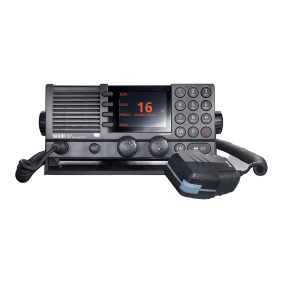
Thrane&Thrane SAILOR 6249 Installation Manual (88 pages)
VHF Survival Craft
Brand:
Thrane&Thrane
| Category:
Transceiver
| Size: 5 MB
Table of Contents
Record of Revisions
6
Related Documents
8
Table of Contents
9
Chapter 1 Introduction
15
VHF Radio
15
Accessories Available
18
Figure 1-1: System Configuration, Example
19
Chapter 2 Installation
21
Unpacking and Initial Inspection
21
Installing the VHF Radio
22
Figure 2-1: Desktop Mounting
23
Table 2-1: Compass Safe Distance
23
Figure 2-2: Overhead Mounting
24
Figure 2-3: Mounting with the Mounting Bracket
25
Figure 2-4: Drilling Plan for the Mounting Bracket
25
Figure 2-5: SAILOR 6249 VHF Survival Craft Dimension for Flush Mount
26
Figure 2-6: Cutout for Flush Mount
26
Figure 2-7: Flush Mount
27
Figure 2-8: SAILOR 6090 Power Converter, Dimensions
28
Figure 2-9: Connecting the SAILOR 6090 Power Converter
28
Connectors
29
Table 2-2: Pin Allocation, Connector at the Front Panel
29
Figure 2-10: Connections at the Rear Panel
30
Table 2-3: Pin Allocation, ACC Connector
31
Table 2-4: Pin Allocation, AUX Connector
32
Table 2-5: Pin Allocation, CTRL Connector
33
Table 2-6: Pin Allocation, LAN Connector
34
Table 2-7: Pin Allocation, Power
34
VHF Antenna Installation
36
Accessories
37
Table 2-8: Part Numbers for Accessories
37
Figure 2-11: SAILOR 6207 Connection Box for Parallel Handsets, Mounting
38
Figure 2-12: SAILOR 6207 Connection Box for Parallel Handsets, Diagram
38
Figure 2-13: SAILOR 6208 Control Unit Connection Box, Mounting
39
Figure 2-14: SAILOR 6208 Control Unit Connection Box for Parallel Handsets, Wiring
39
Figure 2-15: SAILOR 6208 Control Unit Connection Box, Diagram
40
Chapter 3 First-Time Power up
41
General Use and Navigation
41
Chapter 4 Service & Maintenance
43
Contact for Support
43
Maintenance
43
Troubleshooting Guide
44
Table 4-1: Troubleshooting Guide
44
Figure 4-1: Fuse in the Power Connector
45
Figure 4-2: Fuse in the SAILOR 6090 Power Converter
45
Warranty and Returning Units for Repair
46
Appendix A Technical Specifications
47
A.1 Transceiver Unit SAILOR 6249 VHF Survival Craft
47
Transceiver Unit SAILOR 6249 VHF Survival Craft
48
Table A-2: Technical Specifications, Part 2
48
SAILOR 6090 Power Converter 24-12 V
49
Table A-3: Technical Specifications, SAILOR 6090
49
A.2 SAILOR 6090 Power Converter 24—12 V
49
Appendix B System Configurations
51
B.1 System Configuration Examples
51
System Configuration Examples
52
Figure B-1: System Configuration, DC Power Supply 6090
53
Figure B-2: System Configuration, AC Power Supply N163S
54
Figure B-3: System Configuration, DC Power Supply N420
55
Figure B-4: System Configuration, SAILOR 6201, VDR, Loudspeaker and AUX OC
56
Figure B-5: System Configuration, SAILOR 6270 External Loudspeaker
57
Figure B-6: System Configuration, 2 SAILOR 6201 Handsets
58
Figure B-7: System Configuration, Extra SAILOR 6201 Handset in SAILOR 6207
59
Figure B-8: System Configuration, SAILOR 6202 Hand MIC. and SAILOR 6201 Handset
60
Figure B-9: System Configuration, CAN Bus, SAILOR 6204 CSM, Close to the VHF Radio
61
Figure B-10: System Configuration, CAN Bus, SAILOR 6204 CSM, Not Close to the VHF Radio
62
Figure B-11: System Configuration, CAN Bus, SAILOR 6204 CSM, Far from the VHF Radio
63
Figure B-12: System Configuration, CAN Bus, 2 SAILOR 6204 Csms, Close to VHF Radio
64
Figure B-13: System Configuration, CAN Bus, 2 SAILOR 6204 Csms, Far from VHF Radio
65
Figure B-14: System Configuration: CAN Bus, 2 SAILOR 6204 Csms, Close to each Other
66
Figure B-15: System Configuration: CAN Bus, 2 SAILOR 6204 Csms, Close VHF, Small Bridge
67
Figure B-16: System Configuration: CAN Bus, 2 SAILOR 6204 Csms, in Bridge Wings
68
Figure B-17: System Configuration: CAN Bus, 3 SAILOR 6204 Csms, in Bridge Wings
69
Figure B-18: System Configuration: CAN Bus, 4 SAILOR 6204 Csms, in Bridge Wings
70
Figure B-19: System Configuration: CAN Bus, 3 SAILOR 6204 Csms
71
Figure B-20: System Configuration: CAN Bus, 4 SAILOR 6204 Csms
72
Figure B-21: System Configuration: Installation of LAN
73
Cable Requirements
74
B.2 Cable Requirements
74
Table B-1: Cable Overview
74
Table B-2: Cable Specifications for Cable 2
76
Table B-3: Cable Specifications for Cable 3
76
Table B-4: Cable Specifications for Cable 5
77
Table B-5: Cable Specifications for Cable 8 (AUX
78
Table B-6: Cable Specifications for Cable 8 (CTRL
79
Table B-7: Pin Allocation, LAN Connector
80
Glossary
83
Index
85
Advertisement
Advertisement
Related Products
Thrane&Thrane SAILOR 6222 VHF DSC
Thrane&Thrane SAILOR 6217 VHF DSC
Thrane&Thrane SAILOR 6215 VHF DSC Radio
Thrane&Thrane SAILOR 6248 VHF
Thrane&Thrane sailor 6217
Thrane&Thrane SAILOR 6216 VHF DSC
Thrane&Thrane SAILOR 6222
Thrane&Thrane Sailor 6216
Thrane&Thrane SAILOR 6101
Thrane & Thrane SAILOR 6140
Thrane&Thrane Categories
Antenna
Touch terminals
Transceiver
Marine GPS System
Marine Equipment
More Thrane&Thrane Manuals
Login
Sign In
OR
Sign in with Facebook
Sign in with Google
Upload manual
Upload from disk
Upload from URL