Table of Contents
Advertisement
Advertisement
Table of Contents

Related Manuals for Digital Watchdog DW-VAONE 41T


Summary of Contents for Digital Watchdog DW-VAONE 41T
- Page 1 Rev: 0117...
-
Page 2: Safety Information
User’s Manual | 2 Safety Information The safety information is provided for the wellness of the equipment and for the safety of the operator. Please review and observe all instructions and warnings in this manual. Note : Keep this manual handy every time you operate this equipment. Also, check with your dealer for further assistance and for the latest revision of this manual. -
Page 3: Table Of Contents
3 | Full HD Digital Video Recorder Contents 1 : DVR U HAPTER ANUAL ETTING TARTED 1.1 Checking Supplied Items 1.2 Connecting Peripheral Device 1.3 System Startup and Shutdown XPLANATION FOR UNCTION 2.1 Front Panel 2.2 Rear Panel 2.3 IR Remote controllerl PERATION 3.1 User Log-in 3.2 Quick Startup Wizard... - Page 4 User’s Manual | 4 PPENDIX ETWORK ETUP FOR XTERNAL SAGE PPENDIX PECIFICATION...
-
Page 5: Dvr User Manual
5 | Full HD Digital Video Recorder Chapter 1 DVR U ANUAL... -
Page 6: Getting Started
User’s Manual | 6 ETTING TARTED 1.1 Checking Supplied Items Make sure that you have the following items supplied with your DVR. If any of these items are missing or damaged, notify your vendor immediately. Keep the packing utilities for moving or storage purposes afterwards. Items Photo Quantity... -
Page 7: Connecting Peripheral Device
7 | Full HD Digital Video Recorder 1.2 Connecting Peripheral Device This section describes how to connect peripheral devices efficiently to the DVR. Install the DVR on flat surface. If required, attach a rubber mount for installation. If a 19-inch rack is used with 1.5U Height case, it is recommend to install the system on a shelf and use 2.5~3U (1U=1.75 inch or 4.45 cm) space for proper ventilation. - Page 8 User’s Manual | 8 16ch 1HDD type 16ch 2HDD type ※When connecting power cord to the system, it is strongly recommended first to plug the power cord ARNING to the system and then plug the other side of power cord into the wall socket.
-
Page 9: System Startup And Shutdown
9 | Full HD Digital Video Recorder 1.3 System Startup and Shutdown 1.3.1 System Startup After connecting all necessary peripheral devices such as cameras, monitors and a mouse to the DVR, power up the DVR by connecting DC12V adaptor to the power jack on the rear panel. The boot log screen will appear. Please wait until the boot process is complete. - Page 10 User’s Manual | 10 1.3.2 System shutdown and change password To power off the DVR, follow one of the options below: Right-click on the screen and select ‘Shutdown’ from the drop-down menu. Enter the username and password to power off the DVR. Right-click on the screen and select ‘Setup Menu’.
-
Page 11: Explanation For Each Function
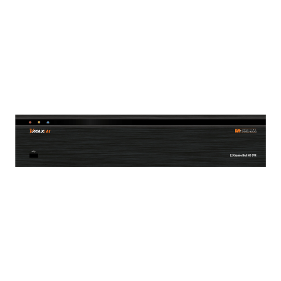
11 | Full HD Digital Video Recorder XPLANATION FOR UNCTION 2.1 Front Panel 4/8/16ch 1HDD type 16ch 2HDD type Items Functions System status LED indicators Green = The system is powered and ON. LED Indicator Red = The system is currently recording Yellow = The system is being accessed remotely via the network USB Port USB Port for Mouse Operation, Backup Device or Firmware Update... -
Page 12: Rear Panel
User’s Manual | 12 2.2 Rear Panel 4ch 1HDD type 8ch 1HDD type 16ch 1HDD type... - Page 13 13 | Full HD Digital Video Recorder 16ch 2HDD type Name Description Video-In Camera inputs (Supports NTSC/PAL) Audio-In Audio Input Device (with Amplifier) Audio-Out Audio Output Device (with Amplifier) USB Port USB 2.0 Port for Mouse Operation, Backup Device, or Firmware Update HD OUTPUT HD OUTPUT LAN Port...
-
Page 14: Ir Remote Controllerl
User’s Manual | 14 2.3 IR Remote Controller(Optional) The VMAX A1 DVR comes with a complimentary IR remote controller The function buttons of the IR Remote Controller are as below. Functions Start Instant Emergency Record Numeric Buttons Auto-Sequence on Live Display Mode Spot out monitor Channel Selection Instant Playback... -
Page 15: Operation
15 | Full HD Digital Video Recorder PERATION 3.1 User Log-in The DVR has various setting categories. The administrator can set the system password and <User> to prevent unauthorized changes to setting values and alteration of recorded file. Enter the <Admin> or <User> password which had been set by using the virtual keyboard. 1) <LOGIN>... -
Page 16: Quick Startup Wizard
User’s Manual | 16 3.2 Quick Startup Wizard Quick Startup Wizard is specially designed to make it much easier for the major DVR settings such as Time/Date setup, Record setup, Network setup and Quick setup. When the DVR boots up, the Quick Startup Wizard operates automatically. It can be disabled by setting in the main menu. -
Page 17: Live Display Mode
17 | Full HD Digital Video Recorder 3.3 Live Display Mode 3.3.1 Full HD(1080p) Live Display Full HD Live Display can be supported in live mode by using its HD output. Able to set max 4k(3840x2160) : HD output and supplied 4K monitor HD Resolution 4K(3840x2160) support only 8ch and 16ch. -
Page 18: Channel Selection
User’s Manual | 18 3.3.2 Channel Selection Channel selection can be done by following one of the steps below: CH1~CH16 buttons in the IR Remote Control. 1~16 virtual buttons at the bottom of the GUI display. The display mode can be changed by selecting the appropriate display mode from the menu bar at the bottom of the display area. - Page 19 19 | Full HD Digital Video Recorder 3.3.3 Icons The live mode display’s icons or messages will be indicated on the screen to indicate the system mode or status. Below are the icon categories that are indicated on the monitor: Icon to be shown Icon to be shown at Left-upper corner on each channel screen...
- Page 20 User’s Manual | 20 3.3.4 Pop-up Menu Right clicking anywhere on the screen will open up the pop up sub-menu as shown below. DISPLAY- Select the display split from the available options: - 1 Screen- Single channel. Automatically displays CH1. If 1 Screen is selected again, next chronological channel will be displayed.
- Page 21 21 | Full HD Digital Video Recorder As the Admin user, you can seup up multiple users with different levels of authorization. If a certain user is not allowed to view a certain camera in live or playback, then no image will appear on the display screen. To create, delete, or modify users, go to the main menu and select system settings.
-
Page 22: Ptz Operation
User’s Manual | 22 3.4 PTZ Operation Before starting PTZ control, please make sure the camera you wish to control is a supported PTZ camera and is installed and configured properly. See section 4.2.6 PTZ for setup information. To enter PTZ mode, follow one of the options below: Right-click on the screen and select PTZ Control. -
Page 23: Spot Out Monitor
23 | Full HD Digital Video Recorder User can automatically switch PTZ camera positions according to defined presets by using the GUARD TOUR function. The connected PTZ camera must support touring functions. “GUARD TOUR” on the pop-up menu can be enabled only in full screen mode. -
Page 24: Playback Of Recorded Video
User’s Manual | 24 3.6 Playback of Recorded Video To play a recorded video, press the Play button from the menu bar, or the Instant Play in the IR remote controller. The recorded files can be seen in rewind or fast forward modes. Press the rewind and fast-forward buttons to control the playback’s speed (x 2, x4, x8, x16, x32 real time). - Page 25 25 | Full HD Digital Video Recorder Button Function Jump to first data. If recording is set to motion, system will jump to previous recorded motion video. Fast rewind Frame-by-Frame Rewind Play video in rewind Pause video Exit Playback to Live mode. Playback video Frame-by Frame playback Fast playback...
-
Page 26: Quick Backup During Playback
User’s Manual | 26 3.7 Quick Backup during Playback User can easily archive video while viewing the video playback. See section 4.5 Export for more information on manual backup from the setup menu. In live mode, right-click anywhere on the screen and select ‘Backup’ to open the backup menu. In playback mode, press the ‘Backup’... -
Page 27: Search Recording Image
27 | Full HD Digital Video Recorder 3.8 Search Recording Image 3.8.1 Date/Time Search To search your recorded data by date/ time, follow one of the options below: Click the quick Menu button at the left side of the menu bar, select Search Date/ Time Right-click anywhere on the screen, select Search ... -
Page 28: Event Log
User’s Manual | 28 AUTION Dark Blue Color The data recorded during DST (Daylight Saving Time) will be indicated in Dark Blue color in the Intelli- Search Bar on playback mode. To view video from the selected time, follow one of the options below: Use the manual hour option to view specific hours of the day. -
Page 29: System Log
29 | Full HD Digital Video Recorder 3.8.3 System Log The system log search allows you to search for any changes made to the system, displaying the search results in a detailed table. To open System Log Search, perform one of the following options: Click quick menu button, select Search... -
Page 30: Dst Setting
User’s Manual | 30 3.9 DST Setting DST starts at 2:00AM local time on 2nd Sunday of March, and ends at 2:00AM DST on 1st Sunday of November. During DST (Daylight Saving Time), the DVR’s clock needs to be adjusted according to regional time zone. The DVR’s time will shift one hour after the DST settings start, and the DVR will restore the time clock back to normal after DST ends. -
Page 31: Schedule Reboot
31 | Full HD Digital Video Recorder When user click the overlapped period, “Recorded video Selection” message will pop up. Select whether to play DST data or Non-DST data. Click OK to play DST image. Click CANCEL to play Non-DST image. [“DST”... -
Page 32: Screen Saver
User’s Manual | 32 3.11 Screen Saver The Screen Saver features protects the screen and data of the DVR by turning off after a set time of inactivity. To enable the Screen Saver, right-click anywhere on the screen and go to the menu setup: SYSTEM > SYSTEM INFO and click “SCREEN SAVER”. -
Page 33: Setting
33 | Full HD Digital Video Recorder ETTING General settings structure consists of “System”, “Device”, “Record”, “Network”, “Export,” and ‘Quick Setup”. To open System Log Search, select one of the following options: Click the button in the quick menu bar and select Setup Menu. Right-click anywhere on the screen and select Setup Menu. -
Page 34: System
User’s Manual | 34 4.1 System 4.1.1 System Info The System Info sub-menu includes the following options: Date/ Time, HD output Resolution, Language, Remote ID, Version & System Upgrade, Video Signal, IP & MAC Addresses, Keyboard Setup, NTP Setup, Display Setup, and Screen Saver Setup. - Page 35 35 | Full HD Digital Video Recorder Upgrading system using Digital Watchdog’s FTP server: Select FTP in the drop-down options under ‘Method’. Enter the FTP’s address: ftp.dwcc.tv NOTE The FTP server address is subject to change without a prior notice Enter the username and password (these should be filled out automatically).
- Page 36 User’s Manual | 36 OSD: Select which information to display in the OSD on each channel in Live. Select which information to display in the OSD on each channel in Playback. Set the OSD’s transparency level. The higher the number, the more transparent the text will appear. Setup a dwell time for the OSD text, after which, the OSD will disappear.
- Page 37 37 | Full HD Digital Video Recorder 4.1.2 User Master user is always the Admin with factory default of No password. This user cannot be deleted. It is recommended to change the Admin’s password for extra security. The admin user can designate a new user with different permission levels by functions, menu access and live &...
- Page 38 User’s Manual | 38 4.1.3 Configuration Copy the system configuration values from this DVR to save for your records or copy to another DVR. “Export” allows you to copy the settings to a USB memory device. “Import” allows you to apply previously saved settings from a USB device and override the current DVR settings.
-
Page 39: Factory Default
The recorded video data will not be erased. 4.1.6 Register Product Registering your Digital Watchdog product speeds up your access to our Technical Support personnel should you require assistance. Please enter all of the information required to set up your account... -
Page 40: Device
User’s Manual | 40 4.2 Device There are seven sub menus in the Device menu, including Camera, Audio, Sensor, Motion Alarm, Extra Alarm, and PTZ. 4.2.1 Camera Users can setup the camera’s title, brightness, contrast, color, motion sensitivity, and audio mapping. The motion area setup is the entire camera area. - Page 41 41 | Full HD Digital Video Recorder Event Camera Group Recording: This feature allows users to setup a recording rule so when a single camera has an event triggered, multiple cameras will start recording. There are a total of four (4) groups you can setup (Group A~D). Each camera can be added to one group only.
- Page 42 User’s Manual | 42 4.2.2 Audio Users can select the audio input and output during live display and match the audio input to a designated channel. (Please refer to Section 4.3.1 Camera Record). In addition, users can listen to the audio for both live display and playback mode through the network using Central Management System (CMS), web browser.
- Page 43 43 | Full HD Digital Video Recorder Preset- Assign apposition for the camera to move to when a sensor is triggered. (This option requires a PTZ camera. See section 4.2.6 PTZ for more information). Relay- OFF/ON- enable or disable relay output when a sensor is activated. ...
-
Page 44: Motion Alarm
User’s Manual | 44 4.2.4 Motion Alarm Select Motion alarm to record only when motion detection is triggered by DVR S/W upon user’s defined motion area. An alarm signal is sent via the selected sensor-out channel. To enable, check the box next to each channel, select the notification option (beep and/ or camera popup), select to enable a relay output when motion alarm is triggered, and set the dwell time for recording. - Page 45 45 | Full HD Digital Video Recorder 4.2.6 UTC/PTZ 1) Connect PTZ Full control and setup of supported PTZ cameras is available in this menu. For more information on controlling PTZ cameras in live mode, see section 3.3 PTZ. Use this setup menu to setup a PTZ camera, adjust the camera’s zoom, focus and iris (on supported models), adjust the pan, tilt and zoom control speed, or setup presets pan, tour and guard schedules.
- Page 46 User’s Manual | 46 PTZ Control mode If check the Continuous, The command is entered in quick succession Control any supported PTZ cameras by moving the mouse pointer. Focus Iris Select the preset number and ‘Set’ button, ‘Move’ button is move to setting area Activate the PTZ menu Enter Zoom In/Out...
-
Page 47: Record
47 | Full HD Digital Video Recorder 4.3 Record Users can configure various record settings such as Continuous, Event, and Panic for each individual channel in the Record Setup Menu. 4.3.1 Record Setup Go to Record Setup. If Quick Setup is selected, record setup will be disabled. To enable, go to Setup Menu > Quick Setup and disable the ‘Use Quick Setup’... -
Page 48: Panic Record
User’s Manual | 48 4.3.2 Panic Record Configure Panic Record settings. These settings are when emergency or panic recording is enabled by a user. To start emergency recording during live view, click the icon from the menu bar at the bottom of the screen. It is highly recommended to use the maximum resolution, FPS, and quality for this recording type. - Page 49 49 | Full HD Digital Video Recorder 4.3.3 Schedule Setup a recording schedule by applying a multiple recording modes to each camera according to date and time. Select a channel you want to setup be pressing the channel number. You can also select the ‘All’ button to apply the recording schedule to all the channels.
-
Page 50: Network
User’s Manual | 50 4.4 Network Use the Network Setup page to configure the DVR’s network settings (for remote connections), DDNS address, and e-mail and software notifications and setup the DVR’s true health check options. 4.4.1 Network The system has built-in web server. ... - Page 51 51 | Full HD Digital Video Recorder Bandwidth Limit- you can limit the Mbps used by the DVR. This is recommended for networks with limited bandwidth. Contact your network administrator for more information. UPnP (Universal Plug and Play) - UPnP is a plug-and-play feature that allows the DVR to be automatically discovered by a PC on the same network.
- Page 52 4.4.2 DDNS Digital Watchdog® offers free and reliable DDNS service support. This allows you to assign the DVR a URL address rather than a long complicated IP Address. This simplified the connection process to the DVR. The DDNS service is supported by Digital Watchdog®...
- Page 53 53 | Full HD Digital Video Recorder 4.4.3 Notification On this setup menu, you can setup the DVR to send event notifications to a remote software or an e-mail address. Notifications Setup- the DVR’s outbound notifications messenger needs to be setup in order to send notifications. DVR Name- This is the name that will appear in the notification’s sender information.
- Page 54 User’s Manual | 54 The system will not send alarm messages or email notification upon motion alarm or sensor unless the recording schedule is set to record according to that event. For example, if user sets “Continuous” only for “Schedule Setup” of the “RECORD” menu and marks the “All”...
-
Page 55: Health Check
55 | Full HD Digital Video Recorder 4.4.4 Health Check The VMAX A1 offers a true DVR health monitoring, with pop-up messages and e-mail notification on video loss, recording failure, and storage failure. To setup: Check the box next to "Enable Health Check" Check the box next to the conditions you would like to be notified on. - Page 56 User’s Manual | 56 4.4.5 Path Finder Click the P2P menu box P2P will be activated, then the success message will be shown Depends on network condition, the connection would be delayed...
-
Page 57: Export
57 | Full HD Digital Video Recorder 4.5 Export 4.5.1 Export Archive video from the DVR’s files to an external storage device. You can also backup video using the “Quick Backup” during playback. See section 3.7 Quick Backup during Playback for more information. Connect USB drive (USB HDD, USB-CD/DVD) with sufficient storage to the DVR and press ‘Scan’. -
Page 58: Quick Setup
User’s Manual | 58 4.5.2 View Export Video If backup player was added to the backup file: Access the backup USB device and select the “Player Launcher.exe” file. Press ‘Open’. Select the backup files you want to view. You can print, capture, zoom in and out, or make an ASF file, from the backup player’s menu. -
Page 59: Web Surveillance
59 | Full HD Digital Video Recorder URVEILLANCE The VMAX A1 DVR has a built-in web server, allowing the user to access the DVR using an ordinary web-browser over a network. The web client allows you to view live monitoring, playback, or remote DVR configuration without installing a remote client software. -
Page 60: Web Configuration
User’s Manual | 60 5.2 Web Configuration The DVR can be remotely configured using the web client. This option is available only when connecting to the DVR remotely using the ‘admin’ user. To enter the DVR’s remote setup, press the ‘Remote Setup’ button on the top right side of the screen. The menu options will be identical to those available on the DVR itself. - Page 61 61 | Full HD Digital Video Recorder [Record] [Network] [Quick Setup] This web GUI screen is directly supported from the built-in web server in the DVR, regardless of Internet connection.
-
Page 62: Web Monitoring
User’s Manual | 62 5.3 Web monitoring 5.3.1 ActiveX Installation The first time you access your DVR via the Web viewer, you will be asked to install an Active-X file before monitoring live video. Please follow the installation process to complete the Active-X installation. Without it, you will not be able to view video from the DVR. - Page 63 63 | Full HD Digital Video Recorder 5.3.3 Web Client View ⑭ ⑬ ① ② ③ ④ ⑫ ⑪ ⑩ ⑤ ⑥ ⑦ ⑨ ⑧ Title Function Connection Mode View the DVR in Live or Playback Mode. Connect or Disconnect from the DVR. Connection Option High quality(Main Stream) or low quality(Second Stream) PTZ control options, including virtual direction arrows, zoom, focus, and preset...
-
Page 64: Web Client Operation
User’s Manual | 64 5.3.3 Web Client Operation User can monitor live video in 1, 4, 9 or 16 screen modes. If user wants to see single channel in full screen, user can double- click on the left mouse button when the cursor is positioned on the live video screen. User can change to single mode by clicking the mode icon located at the bottom left. -
Page 65: Web Playback
65 | Full HD Digital Video Recorder 5.4 Web Playback Using the DVR’s web client, you can remotely playback video from the DVR by clicking “SEARCH” in the top of the left side panel. To connect to the DVR in search mode: Check the box next to ‘Search’... - Page 66 User’s Manual | 66 PPENDIX ETWORK ETUP FOR XTERNAL SAGE Please note: The following information are general guidelines. These may vary by network and router specifications. Contact your Network Administrator or Internet Service Provider for additional information. If you are not connecting to your DVR from within the same network, you will have to perform port forwarding on your router to access the DVR externally, via the internet.
- Page 67 67 | Full HD Digital Video Recorder PPENDIX PECIFICATION 1HDD Type Model 16ch Front Image Compression H.264 HDD Interface 1 x SATA Operation System Embedded Linux Input 4BNC 8BNC 16BNC Video Output 1 HD Output, 1 VGA OUT, 1 SPOT OUT Video Mode NTSC 240fps@1080P...
- Page 68 User’s Manual | 68 1HDD Type Model 16ch Central Management System Remote Web(IE) Live monitoring, Playback & System Configuration Management Internal Backup Device Local backup by USB memory stick (2ea) , External Network backup by CMS support Multi-Language, System Upgrade by USB & Network, Help menu on Major Function Advanced Function Import &...
- Page 69 69 | Full HD Digital Video Recorder 2HDD Type Model 16ch Front Image Compression H.264 HDD Interface 2 x SATA Operation System Embedded Linux Input 16BNC Video Output 1 HD Output, 1 VGA OUT, 1 SPOT OUT, 2 LOOP OUT Video Mode NTSC Display Speed...
- Page 70 User’s Manual | 70 2HDD Type Model 16ch Central Management System Remote Web(IE) Live monitoring, Playback & System Configuration Management Internal Backup Device Local backup by USB memory stick (2ea) , External Network backup by CMS support Multi-Language, System Upgrade by USB & Network, Help menu on Major Function Advanced Function Import &...
Need help?
Do you have a question about the DW-VAONE 41T and is the answer not in the manual?
Questions and answers