Table of Contents
Advertisement
Advertisement
Table of Contents

Related Manuals for Digital Watchdog VMAX


Summary of Contents for Digital Watchdog VMAX
-
Page 2: Safety Information
1 | H.264 Digital Video Recorder Safety Information The safety information is provided for the wellness of the equipment and for the safety of the operator. Please review and observe all instructions and warnings in this manual. Note: Keep this manual handy every time you operate this equipment. Also, check with your dealer for further assistance and for the latest revision of this manual. -
Page 3: Table Of Contents
User Manual | 2 Contents 1 : DVR U HAPTER ANUAL ETTING TARTED 1.1 Checking Supplied Items 1.2 System Application Overview 1.3 System Startup and Shutdown 1.4 Front Panel 1.5 Rear Panel 1.6 IR Remote Controller PERATION 2.1 User Login 2.2 Live Display Mode 2.3 Freeze Mode 2.4 Call Monitor Operation... - Page 4 3 | H.264 Digital Video Recorder 2 : ACS C HAPTER LIENT OFTWARE ANUAL 5 ACS (A DVANCE LIENT OFTWARE UIDE 5.1 Recommended PC Requirements 5.2 Install 5.3 Uninstall 5.4 Basic Operation 5.5 Advanced Operation 5.6 ACS Setup 3 : MAC ACS C HAPTER LIENT OFTWARE...
-
Page 5: User Manual | 4
User Manual | 4 Chapter 1 DVR U ANUAL... - Page 6 5 | Chapter 1 : DVR User Manual...
-
Page 7: Getting Started
User Manual | 6 ETTING TARTED 1.1 Checking Supplied Items Make sure that you have the following items supplied with your DVR. If any of these items are missing or damaged, notify your vendor immediately. Do not dispose of the packing utilities in case of moving or storage purposes. Items Photo Quantity... -
Page 8: System Application Overview
7 | Chapter 1 : DVR User Manual 1.2 System Application Overview This section describes how to connect peripheral devices to the DVR according to your application. Install the DVR on a flat surface. If required, attach a rubber mount for installation. If a 19-inch rack is used with 1.5U Height case, it is recommend to install the system on a shelf and use 2.5~3U (1U=1.75 inch space for proper ventilation. -
Page 9: System Startup And Shutdown
User Manual | 8 1.3 System Startup and Shutdown 1.3.1 System Startup After connecting peripheral devices such as cameras, monitors, and a mouse to the DVR, connect the 12vDC 6.6Amps power supply to the power jack on the rear panel of the DVR. The boot-up screen will display as shown below. -
Page 10: Front Panel
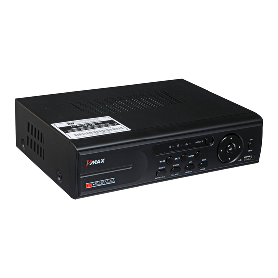
9 | Chapter 1 : DVR User Manual 1.4 Front Panel Front panel allows the user to operate the DVR without having to use the IR remote or a mouse. I- Backup (Instant Backup) In playback mode, the user can press the [I-BACKUP] button on the frontal keypad to configure both Start and End time. -
Page 11: Enter Button
User Manual | 10 1.4.1 Directional Arrows: 1) Live Display & Playback Mode Change channel number by using Left & Right Arrow buttons. Change display mode by using up & down Arrow buttons. 2) Menu Setup Use to select function at the menu setup display. 3) PTZ control (When PTZ button is pressed) 4) Zoom &... - Page 12 11 | Chapter 1 : DVR User Manual 1.4.8 SEARCH (Press Once) / INSTANT PLAY (Press and Hold) Button SEARCH (Press Once): To search for recorded videos by date and time INSTANT PLAY (Press and Hold): To start Instant Reverse Playback Refer to [OPERATION >...
-
Page 13: Rear Panel
USB Port (Ver 2.0) for Mouse Operation, Backup Device, or Firmware Update VGA Port VGA Monitor LAN Port 100Mbps RJ45 Ethernet Connection Terminal Power Supply Connection 12 vDC at 3.33Amps 4Channel VMAX Power Input 12vDC at 6.67Amps for 8 & 16 Channel VMAX Sensor Input Sensor Input... -
Page 14: Alarm Terminal Block
13 | Chapter 1 : DVR User Manual 1.5.4 Video-Out To connect Main composite monitor 1.5.5 Spot-Out To connect composite Spot Monitor 1.5.6 VGA-Out To connect a VGA Monitor 1.5.7 USB Port (Version 2.0) 1) To backup recorded video, using a USB flash drive (USB Memory Stick or USB HDD) 2) To upgrade the firmware 3) To connect a mouse for system navigation 1.5.8 LAN Port... -
Page 15: Ir Remote Controller
User Manual | 14 1.6 IR Remote Controller The IR remote control allows the use to operate the DVR without having to use the mouse or the front panel buttons. To use IR Remote Controller, the ID of the IR Remote Controller must be same as the ID of the DVR. Default ID # for DVR and IR Remote Controller is “1”. -
Page 16: Operation
15 | Chapter 1 : DVR User Manual PERATION 2.1 User Login The DVR has various configurations. The administrator can set the system password and can prevent the User(s) from making unauthorized changes to the configurations or recorded video Default Login is “admin” and the password box is blank a then press [OK] or Enter button Using the virtual keyboard to enter the password if required 1) [LOGIN] window will display on the monitor, until user logs in with the correct [User] and [Password]. -
Page 17: Live Display Mode
User Manual | 16 2.2 Live Display Mode 2.2.1 Channel Selection After the camera channels are connected, the live real-time display mode is controlled through an easy button operation. The images can be seen on real-time by 1, 4, and PIP screen. Press the Up & Down Arrow buttons on the front panel or IR remote controller to change the display screen sequentially. - Page 18 17 | Chapter 1 : DVR User Manual Administrator user can set different level of authorization for each user. If a certain user is not allowed to view a certain live and playback channel, then no image appears on the display screen. Refer to 4.1.2 User for details on how to setup. When a camera is disconnected, an alarm sound will be activated depending on the system settings.
-
Page 19: Icons Description
User Manual | 18 2.2.2 Icons Description Icon Shown on Upper Right Corner Icon Shown on Bottom Right Corner Continuous Recording PTZ Camera Motion Detection Recording No HDD, Smart Alarm & HDD Failure Sensor Activating Recording Using PTZ Continuous+ Motion Recording Showing sequence mode Continuous + Sensor Activating Showing digital zoom mode... - Page 20 19 | Chapter 1 : DVR User Manual 2.2.3 Toolbar Move the mouse cursor to the bottom of the screen monitor during live mode and the menu bar will appear instantly, as shown below. Instant Emergency Recording, which is useful to start recording when the user notices an unusual activity. In emergency recording, the system follows the [Panic Record] settings.
- Page 21 User Manual | 20 2.2.4 Pop-up Menu Place the mouse cursor anywhere on the screen and click the right button of the mouse to display the popup menu as shown below. When [SEQUENCE] is selected, icon is shown on the bottom right corner of the screen, and the display screen will be changed sequentially.
-
Page 22: Freeze Mode
21 | Chapter 1 : DVR User Manual 2.3 Freeze Mode Press [FREEZE] button on the front panel; or click the right button on the mouse when viewing a live image and select the [FREEZE] option on the pop-up menu. In the Freeze mode, the image pauses; the date/ time information does not; and the system clock continues running. -
Page 23: Ptz Operation
User Manual | 22 2.5 PTZ Operation User can go to PTZ mode by clicking right button of mouse and selecting [PTZ CONTROL] in the pop-up menu as shown below or by selecting the button on the menu bar located on the bottom of the main screen. In PTZ mode, user can control PTZ operation with USB mouse. - Page 24 23 | Chapter 1 : DVR User Manual The user can also select the [PRESET], [GUARD TOUR], or [EXIT PTZ CONTROL]. User will see numeric pad to select Preset number. The preset is defined by setting a PTZ protocol in the setting menu. The maximum number of preset is 255, but the max supported by the PTZ may be less.
-
Page 25: Instant Playback Of Recorded Video
User Manual | 24 2.6 Instant Playback of Recorded Video To play a recorded image, press the [PLAY] button from the Front Panel or IR Remote Controller. It is easy to use the USB mouse to playback recording files. The recorded files can be played backwards or forwards. Press the [REWIND] and [FAST FORWARD] buttons, and the playback speed can be controlled in steps of 2, 4, 8, 16, 32 times the real-time when playing backwards or forwards. -
Page 26: Clean Button During Playback
25 | Chapter 1 : DVR User Manual 2.7 Clean Button During Playback De-interlacing feature is required for smooth playback of video that is recorded in D1 (720x480/576) resolution. In playback mode, user can press [CLEAN] icon at the menu bar located in the bottom of the main screen. After clicking [CLEAN] icon, a blue circle forms around the icon, which means de-interlacing has been activated. -
Page 27: I-Backup (Quick Backup During Playback)
User Manual | 26 2.8 I-Backup (Quick Backup During Playback) Press [floppy Icon) and Connect an appropriate USB flash drive and press [SCAN] button to get the system to recognize the device before archiving. Necessary file size will be shown before burning. Users can check the [AUTO PLAYER] box to include the viewer file. -
Page 28: Search Recording Image
27 | Chapter 1 : DVR User Manual 2.9 Search Recording Image 2.9.1 Date/Time Search Select [Date/Time] in Setup Menu to search for a certain file within the recorded video data. The calendar displays dates with recorded video data in RED color. Click one of the desired dates in Red. Then, the recorded data for the selected date will appear. - Page 29 User Manual | 28 No Recording N O Color The DVR does not record, even though user sets a MODE of recording in [RECORD SETUP] tab. Panic Recording RED Color Continuous Recording YELLOW Color The DVR records all the time for the set camera(s). Motion Detection Recording GREEN Color The DVR only records when it detects motion.
-
Page 30: First Data
29 | Chapter 1 : DVR User Manual 2.9.2 First Data Go to the first screen of the recorded videos. This is the oldest recorded video. 2.9.3 Last Data Go to the last screen of the recorded video. This is the most recent recorded video. 2.9.4 Event Log The Event Log Search finds particular events, quickly and easily. -
Page 31: System Log
User Manual | 30 2.9.5 System Log The System Log Search finds particular system log information, quickly and easily. User can copy this event list to USB memory device in text file format. Once export is completed, the user can find a folder titled with the exported date created in the USB thumb drive. There is [system.log] file stored in the folder. - Page 32 31 | Chapter 1 : DVR User Manual The following are the categories indicated on the system log viewer. Log by System Log by Setup Log by Network Each page of the [System Log] and [Event Log] Window displays 20 logs. User can view the next set of logs on another page by clicking the arrow icons.
-
Page 33: Dst Setting And Screen Saver
User Manual | 32 2.10 DST Setting and Screen Saver DST starts at 2:00 local time on 2 Sunday of March, and ends at 2:00 DST on 1 Sunday of November. During DST (Daylight Saving Time), the DVR time clock adjusts to the regional time zone. The clock will shift by one hour after the DST settings start and will delay by one hour after DST finishes. - Page 34 33 | Chapter 1 : DVR User Manual [DST Image] [Non-DST Image]...
- Page 35 User Manual | 34 To set a screensaver on the DVR, go to the menu [SYSTEM > SYSTEM INFO] and click [SCREEN SAVER] to get the Screen Save window as shown below. Users can select [CRT] and/or [VGA] by checking the boxes. Users can set the WAITING TIME for when the monitor will automatically turn off.
-
Page 36: Setting
35 | Chapter 1 : DVR User Manual ETTING General setting structure consists of System, Device, Record, Network, Backup, and Quick Setup as shown below. [SYSTEM] [DEVICE] [RECORD] [NETWORK] [BACKUP] [QUICK SETUP]... - Page 37 User Manual | 36 Main Menu Sub Menu SYSTEM INFO USER SYSTEM EXPORT/IMPORT FACTORY DEFAULT CAMERA AUDIO SENSOR DEVICE MOTION ALARM EXTRA ALARM RECORD SETUP PANIC RECORD RECORD SCHEDULE HOLIDAY NETWORK NETWORK DDNS NOTIFICATION BACKUP MANUAL BACKUP QUICK SETUP QUICK SETUP...
-
Page 38: System
37 | Chapter 1 : DVR User Manual 3.1 System The Menu button is selected by clicking [TOOL] on the menu bar or clicking the right mouse button. Users can move mouse pointer from [SYSTEM] to [QUICK SETUP] to instantly look around the sub-menus on the menu screen. Using the left mouse button, the user can select a desired category for editing. - Page 39 User Manual | 38 Remote ID: The Remote ID should match the ID of the IR Remote Controller in order for the remote to function. Keyboard ID: The Keyboard ID should match the selected DVR on the keyboard. In addition, the baud rate and Keyboard should match the selected keyboard controller.
- Page 40 39 | Chapter 1 : DVR User Manual It is recommended to format the HDD after finishing the firmware upgrade because the data recorded by previous AUTION firmware may cause malfunction of DVR due to the difference in format. It is possible to send the system firmware back to factory default. This may be useful if some of the functions do not work properly after a firmware upgrade.
- Page 41 User Manual | 40 3.1.2 User “Admin” with no factory default password is always the main user of the DVR. Admin should change the password of the DVR for extra security. Admin can add new users with different permission levels in areas of Function, Menu Access, and Live & Playback. [FUNCTION] consists of Search, PTZ, Backup, and Playback.
- Page 42 41 | Chapter 1 : DVR User Manual 3.1.3 Export/Import Users can copy and paste the system configuration values in this menu. [EXPORT] enables user to copy the settings for the DVR to any USB memory devices. [IMPORT] enables user to recall the settings saved from other systems using CD/DVD/USB memory devices. During the import process, make sure that the firmware version of source DVR is the same as the destination DVR.
- Page 43 User Manual | 42 3.1.4 HDD [HDD] tab displays the HDD information. SATA HDD is used for the VMAX. HDD Full : When HDD is full, the DVR can overwrite old data or stop recording. Check [OVERWRITE] or [REC STOP].
-
Page 44: Factory Default
43 | Chapter 1 : DVR User Manual If system resources are busy with task, such as making a network connection or performing video playback during the format process, the format may fail. If the format fails, reboot the system resources and then try to format again. [Format Completed] 1) Formatting may take around 2 minutes for 250GB, 3 minutes for 500GB, or 4 minutes for 750GB. -
Page 45: Device
User Manual | 44 3.2 Device The [DEVICE] button consists of the following submenus: Camera, Audio, Sensor, Motion Alarm, Extra Alarm, and PTZ. 3.2.1 Camera The [CAMERA] tab enables user to change camera settings. Users can change Title, Covert, Brightness, Contrast, Color, Sensitivity, Audio Mapping, and Motion Area Setting for each camera. - Page 46 45 | Chapter 1 : DVR User Manual 3.2.2 Audio Users can select the audio input and output during live display and match the audio input to a designated channel. (Please refer to Section 4.3.1 Camera Record for more details. User can raise or drop the volume by using the volume control panel.
- Page 47 User Manual | 46 3.2.3 Sensor • Type: Select from [OFF], [N.O], and [N.C]. • Cam: Select the associated camera. Notify: Click the down arrow button below Notify to select how to be alerted when a sensor is activated or a motion •...
-
Page 48: Motion Alarm
47 | Chapter 1 : DVR User Manual 3.2.4 Motion Alarm [MOTION ALARM] records only when DVR S/W triggers motion detection within the defined motion area. If user sets Intensive to [ON], the DVR records at the maximum recording speed upon motion detection. Video will record for the selected post-alarm dwell time, and pre-alarm video will record for the specified time. - Page 49 User Manual | 48 3.2.6 PTZ Full control of PTZ cameras is available in this menu. Please refer to Section 3.3 PTZ Operation for details. • PTZ Menu (Depending on the model of PTZ camera): If selected, the OSD menu of PTZ camera is imported and shown on the DVR monitor allowing the user to control the full PTZ settings.
-
Page 50: Record
49 | Chapter 1 : DVR User Manual 3.3 Record Configure various record settings such as Continuous, Event, and Panic for each individual camera channel in the Record Setup Menu. Network Stream settings are configured independently from the record settings in this menu as well. Therefore, the user can optimize the bandwidth used by configuring the resolution, FPS, and image quality separately. - Page 51 User Manual | 50 Record Mode “M” (Motion Detection) or “S” (Sensor/Alarm) uses the Event Recording Settings only. [Event Record Setting] Record Mode “C+M” (Continuous + Motion), “C+S” (Continuous + Sensor), or “C+M+S” (Continuous + Motion + Sensor) simultaneously engages both Continuous and Event Recording Settings. DVR records with continuous record settings, but when there is an event (Motion, Sensor, and Alarm), the DVR records with the Event Record Settings.
- Page 52 51 | Chapter 1 : DVR User Manual [FPS and Quality Setup] Select the FPS (Frames Per Second) for each camera channel. The system automatically calculates [Remaining FPS] that users can use. Quality influences the “byte size per image.” When Quality is [Low], both image quality and size is lower. When Quality is [High], both image quality and size is higher.
- Page 53 User Manual | 52 The maximum number of FPS is 480(400)FPS for the DVR. If the recording setting exceeds the limit while users setup the Resolution and FPS, the popup message “Please check FPS setting.” will appear. Please setup the resolution and FPS again based on the “Remaining FPS”.
- Page 54 53 | Chapter 1 : DVR User Manual Configure the Network Stream Settings independently from the Record Settings. Click [LIVE STREAM] button. [LIVE STREAM] window will now appear, as shown below. [LIVE STREAM] enables users to optimize data transmitted over the network by configuring the Resolution, FPS, and Quality without affecting the Record Settings.
- Page 55 User Manual | 54 3.3.2 Schedule Set the Recording Schedule. All Schedules is marked for recording as factory default. To cancel recording for a specific time, select [CLEAR] button and click or drag the specific date/time. When Advanced Setting is select [SCHEDULE 1], [SCHEDULE 2], or [ALL] button and click the specific date/time.
- Page 56 55 | Chapter 1 : DVR User Manual 3.3.3 Holiday Click [HOLIDAY] tab to assign holidays. Assign a unique schedule for holidays in the [SCHEDULE] tab.
-
Page 57: Network
User Manual | 56 3.4 Network 3.4.1 Network The DVR has a built-in web server. Network Type: Select network type. Select LAN for fixed (Static) IP or DHCP for dynamic IP. • If you select DHCP, click [IP DETECT] button to detect the network information. •... - Page 58 57 | Chapter 1 : DVR User Manual • UPnP (Universal Plug and Play): UPnP stands for Universal Plug and Play, which indicates a universal protocol for widespread plug-and-play devices to ease the network implementation. When the PC and DVR have the UPnP installed, the PC automatically begins to recognize the DVR in the same local area network.
- Page 59 User Manual | 58 Auto Private IP Setup (NAT Traversal): The UPnP NAT Traversal function will help to setup the DVR to connect to the internet via • a router. When a PC connects to a DVR that is not in the same local area network, a real IPO Address and corresponding Port Number is required.
- Page 60 The standard DDNS domain name is [dwddns.net], and users can switch to [dyndns.com] in the drop-down list. -Technical Tips- 1. If your DW-VMAX is connected behind the router be sure to login to your router to open TCP/IP:port,Mobile:Port;Web: port and forward them to the DVR IP address 2.
- Page 61 User Manual | 60 3.4.3 Notification • Remote Notify: The system can notify an alarm message to the IP address of ACS (Advanced Client Software) over the network. Choose from a selection of different kinds of alarms by pressing [ADD] button. Sensor, Motion Detection, Disk Full, Admin PW Changed, Video Loss, and Power On/Off.
-
Page 62: Backup
61 | Chapter 1 : DVR User Manual 3.5 Backup 3.5.1 Manual Backup Users can archive a video clip recorded for a certain period on a selected channel or channels as shown below. Connect an appropriate USB flash drive and press [SCAN] button to get the system to recognize the device before archiving. Necessary file size will be shown before burning. - Page 63 User Manual | 62 3.5.2 ACS (Advance Client Software)Backup Player If [AUTO PLAYER] is checked, there will be a single file after archiving. Double-click the backup file to open the video data file. If the backup file does not have Auto Player, double-click [BackupPlayer.exe] file in the folder titled with the date to open the video data file in PSF format.
-
Page 64: Quick Setup
63 | Chapter 1 : DVR User Manual 3.6 Quick Setup [QUICK SETUP] enables easy setup for recording resolution, recording speed by frame, recording mode, and recording periods. The system will follow the configurations for [QUICK SETUP] regardless of configurations set in other menus. Do not check [USE QUICK STEUP], if you want to use full system configuration defined in other menus. -
Page 65: Web Surveillance
User Manual | 64 URVEILLANCE The DVR has a built-in web server. With an ordinary web-browser over the network, users can stay connected to the system for monitoring, playback, or remote configuration without an Advanced Client Software (ACS). 4.1 Web Login Indicate the Web Port in the Router;... - Page 66 65 | Chapter 1 : DVR User Manual After logging in with the correct User ID and password, user can make various configuration changes in the Web Configuration window seen below. The Web Configuration Menu is only available to the administrator (admin) account. [SYSTEM] [DEVICE] [RECORD]...
- Page 67 User Manual | 66 This DVR has its own built-in web server. This Web CGI Screen is supported directly from the built-in web server of the DVR, regardless of Internet connection. [SYSTEM REBOOT] enables you to reboot the system without any changes to the setup. When the network is disconnected due to abnormal operation of the system, user can use this function and try to reconnect.
-
Page 68: Web Monitoring
67 | Chapter 1 : DVR User Manual 4.3 Web Monitoring The Active-X file from the DVR has to be installed to the workstation PC to monitor live video. Click [INSTALL] button. Click [NEXT] button to continue setup. When setup is complete, click [FINISH] button. Click [CONNECT] button located on the top left corner to connect to the DVR. - Page 69 User Manual | 68 The image resolution of the live view in the web browser is transferred from the DVR. (Live image over the web browser depends on the [LIVE STREAM] Value on record mode of DVR.) Refer to 4.3.1 Record Setup for details. If IE Web Browser does not properly display live image due to network traffic jam or narrow bandwidth, close and re-open the IE Web Browser.
-
Page 70: Web Playback
69 | Chapter 1 : DVR User Manual 4.4 Web Playback Remotely playback the DVR images by marking the [SEARCH] box on the top left corner of the Web Browser. Click [CONNECT] button to connect to the DVR. Time Search: Select the date and time on Time Search, located at the center left of the window. Click button. - Page 71 User Manual | 70 Chapter 2 ACS C LIENT OFTWARE ANUAL...
- Page 72 71 | Chapter 2: ACS Client Software User Manual...
-
Page 73: Recommended Pc Requirements
User Manual | 72 5 ACS (A DVANCE LIENT OFTWARE UIDE 5.1 Recommended PC Requirements Recommended PC Requirements Windows XP, Vista, 7 Pentium Dual Core 1.8GHz or higher 1024*768, 256MB Supporting DirectX 20MB for installation, 10GB for Remote Backup Minimum PC Requirement Windows XP, Vista Pentium 4, 2GHz 1024*768, 64MB 24Bit Color Graphic Card... -
Page 74: Install
73 | Chapter 2: ACS Client Software User Manual 5.2 Install Run [Advanced Client Software Setup.exe] on CD. Then, a Setup Window will appear as below. Press [BROWSE…] button if you want to install the program into a different directory. Click [NEXT] button. Press [BROWSE…] button if you want to place the shortcuts into a different folder. - Page 75 User Manual | 74 Press the [NEXT] button to move to the next screen. To create a desktop icon, check [CREATE A DESKTOP ICON] box. Press the [INSTALL] button to move to the next screen and begin installation. When the installation is complete, the following message appears.
-
Page 76: Uninstall
75 | Chapter 2: ACS Client Software User Manual 5.3 Uninstall To uninstall ACS, press [Uninstall ACS] from Start Menu. Account Manager will appear in Windows7 or Windows Vista. Press [YES] to begin uninstalling. The window below appears. When the un-installation is complete, the following message appears. -
Page 77: Basic Operation
User Manual | 76 5.4 Basic Operation Click on icon on Desktop or click on [ACS] link in the start menu. 5.4.1 Login Administrator is the highest level of authority for the operation of ACS (Advanced Client Software). Default ID and Password for Administrator - User ID: administrator - Password box is blank... -
Page 78: Screen Layout
77 | Chapter 2: ACS Client Software User Manual 5.4.2 Screen Layout Description Item ACS Setting, Live Mode, Search, Disconnect, Image Save, Video Save, Screen Mode ACS Toolbar Remote Setup Sites (DVRs) Registered and configured DVR Site list List Panel PTZ Panel PTZ Camera Control in Live Mode Calendar Panel... -
Page 79: Tool Bar
User Manual | 78 5.4.3 Tool Bar Icon Description ACS Setup Option Setup for ACS (Advanced Client Software) Live Connect and Display Live channels from selected DVR Search Connect and Display Recorded channels from selected DVR Disconnect Disconnect a Selected Channel Disconnect All Disconnect All Channels Image... -
Page 80: Ptz Control Panel
79 | Chapter 2: ACS Client Software User Manual 5.4.5 PTZ Control Panel PTZ Camera Control in Live Mode Description Button Directional Arrows Move PTZ Cameras in 8 directions. ZOOM Zoom In (+) & Zoom Out (-) FOCUS Focus In (+) & Focus Out (-) Virtual PTZ Click button to use mouse to control PTZ cameras. -
Page 81: Search Panel
User Manual | 80 5.4.7 Search Panel Search Panel is only available in search mode. • The Search Panel shows the recorded data for each channel. Record Mode is distinguished by color. No Record White Continuous (Yellow) Panic (Red) Alarm (Orange) Motion (Green) In the Search Panel, click the time or move the vertical blue bar to the time you want to playback. - Page 82 81 | Chapter 2: ACS Client Software User Manual Audio Control • (Audio On/Off): Turn On or Off for Audio channel. Two-way Audio : Two-Audio between ACS and DVR. • 5.4.8 Display Channel • Showing Live or Search Mode In Live Mode, the text “Live” will be displayed in white, and the screen will be bordered in blue. •...
-
Page 83: Advanced Operation
User Manual | 82 5.5 Advanced Operation Click the right button of the mouse to display the popup menu. As shown to select: Add DVR Site Live Search Disconnect Disconnect All Event Search Remote Backup Firmware update Remote Setup for the DVR remote configuration 5.5.1 Event Search Place the mouse cursor on the Site List Panel and click the right mouse button. - Page 84 83 | Chapter 2: ACS Client Software User Manual Function Description Connection Info Type in the DVR info to connect. Progress Bar Shows the progress. Dates with events will be displayed in bold font. Click the date to start Event Calendar Search Search.
-
Page 85: Remote Backup
User Manual | 84 5.5.2 Remote Backup Place the mouse cursor on the Site List Panel and click the right mouse button. A popup menu will appear. Click [REMOTE BACKUP]. Function Description Connection Info Type in the DVR info to connect. Recording Directory Select or change the backup directory. -
Page 86: Firmware Upgrade
85 | Chapter 2: ACS Client Software User Manual 5.5.3 Firmware Upgrade Place the mouse cursor on the Site List Panel and click the right mouse button. A popup menu will appear. Click [FIRMWARE UPGRADE]. Function Description Connection Info Type in the DVR info to connect. Firmware Directory Select the new firmware to upgrade. -
Page 87: Acs Setup
User Manual | 86 5.6 ACS Setup This is for DVR Registration, User, Display, and Other Options. 5.6.1 DVR Registration Place the mouse cursor on the Site List Panel and click the right mouse button. A popup menu will appear. Select DVR Registration [ADD], [EDIT], or [REMOVE] DVR site information. - Page 88 87 | Chapter 2: ACS Client Software User Manual To modify and/or remove DVR information, click [Add] or [Remove] to amend DVR site information. After clicking [OK], the new DVR information will appear on the DVR Site List Panel. 5.6.2 Add / Edit / Remove ACS (Advance Client Software) User User authority can be changed by Administrator account.
- Page 89 User Manual | 88 5.6.3 Display Go here to setup [OSD]. Time Format Sync (DVR: ACS): This option synchronizes the DVR time format with ACS. 5.6.4 Event...
- Page 90 89 | Chapter 2: ACS Client Software User Manual 5.6.5 Misc. Function Description Recording Directory Select or change the directory for where your still images and videos are saved. Event Type in the Event Port to receive the event list. 1025 ~ 60000 is recommended. Language Select the ACS language.
- Page 91 User Manual | 90 Chapter 3 MAC ACS C LIENT OFTWARE ANUAL...
- Page 92 91 | Chapter 3: Mac ACS (Advance Client Software)
-
Page 93: Mac Requirements
User Manual | 92 6 MAC ACS U UIDE 6.1 Mac Requirements Recommended Mac Requirements Mac OS X 10.6 (Snow Leopard) Built-in Intel CPU MAC Recommended More than 128MB Recommended More than 1GB 20MB Free Space Minimum Mac Requirements Mac OS X 10.5 (Leopard) Built-in Intel CPU MAC 64MB 512MB... -
Page 94: Install
93 | Chapter 3: Mac ACS (Advance Client Software) 6.2 Install Run [MAC ACS.pkg] on CD, and the below setup menu will appear. Select the HDD where you wish to install the program. Press the [CONTINUE] button to move to the next screen. Press the [INSTALL] button to move to the next screen. - Page 95 User Manual | 94 Type in the password and Click [OK] to begin installation. When the installation is complete, the following message will appear. Click [CLOSE] to close the window.
-
Page 96: Basic Operation
95 | Chapter 3: Mac ACS (Advance Client Software) 6.3 Basic Operation Click on [ACS] icon located in the Application Folder. 6.3.1 Screen Layout... - Page 97 User Manual | 96 Item Description Site Manager, Connect, Disconnect, Disconnect All, Print, JPG Export MOV Export, Screen Main Toolbar Display Mode DVR List Panel Registered DVR Site List; Connect by Drag & Drop Live or Search Click Live or Search Mode to connect to the sites. Connect Panel PTZ Panel PTZ Camera Control in Live mode...
- Page 98 97 | Chapter 3: Mac ACS (Advance Client Software) 6.3.2 Main Toolbar Button Description Site Manager Register or delete DVR Site Connect to a selected DVR site, listed on the DVR list panel. Connect Select Live or Search mode at Connect Mode Panel. Disconnect Disconnect a selected channel.
-
Page 99: Ptz Panel
User Manual | 98 6.3.4 PTZ Panel PTZ Camera Controls in Live Mode. PTZ Camera can be controlled if the channel is activated on PTZ operation. Button Description Navigation Keys Move PTZ Cameras in 8 directions. ZOOM Zoom In (+) and Zoom Out (-) FOCUS Focus In (+) and Focus Out (-) PRESET... - Page 100 99 | Chapter 3: Mac ACS (Advance Client Software) 6.3.6 Search Panel Search Panel is only available in Search Mode. The Search Panel shows the recorded data for each channel. • Record Mode is distinguished by color. • No Record Background Color Continuous (Yellow Color) Panic (Red Color)
- Page 101 User Manual | 100 6.3.7 Site Manager [ADD], [MODIFY], or [REMOVE] DVR site information. Press to register a DVR. The default value is registered...
- Page 102 101 | Chapter 3: Mac ACS (Advance Client Software) To modify, double-click on the item. For example, double-click [new site] to change the name. Press after modifications has been made. Function Description Name Enter the location name or the DVR name of the site to be registered. Address Enter the IP address or DDNS (DVR Name) of the DVR Port...
- Page 103 User Manual | 102 Chapter 4 OBILE HONE OFTWARE ANUAL...
- Page 104 103 | Chapter 4: Mobile Phone Software User Manual...
-
Page 105: Iphone Application Software
User Manual | 104 OBILE HONE OFTWARE UIDE 7.1 iPhone Application Software... - Page 106 105 | Chapter 4: Mobile Phone Software User Manual...
- Page 107 User Manual | 106...
- Page 108 107 | Chapter 4: Mobile Phone Software User Manual...
-
Page 109: Android Application Software
User Manual | 108 7.2 Android Application Software... - Page 110 109 | Chapter 4: Mobile Phone Software User Manual...
- Page 111 User Manual | 110...
- Page 112 111 | Chapter 4: Mobile Phone Software User Manual...
- Page 113 User Manual | 112...
-
Page 114: Blackberry Application Software
113 | Chapter 4: Mobile Phone Software User Manual 7.3 Blackberry Application Software... - Page 115 User Manual | 114...
- Page 116 115 | Chapter 4: Mobile Phone Software User Manual...
- Page 117 User Manual | 116...
- Page 118 117 | Chapter 4: Mobile Phone Software User Manual...
-
Page 119: Using Wap+3G Connection
User Manual | 118 7.4 Using WAP+3G Connection... - Page 120 119 | Chapter 4: Mobile Phone Software User Manual...
- Page 121 User Manual | 120...
-
Page 122: A Ppendix : S Pecification
121 | Appendix: Specification PPENDIX PECIFICATION MODEL 4CH Compact Case 8/16CH with DVD±RW Photo Compression Algorithm Video : H.264, Audio : G723.1 1ea x SATA 2ea x SATA MAX. 2TB HDD MAX. 4TB HDD (2TB X 2EA) Embedded Linux Input 8/16CH Video Looping... - Page 123 User Manual | 122 MODEL 4CH Compact Case 8/16CH with DVD±RW Speed x1, x2, x4, x8, x16, x32 8CH: 1, 4, 9 Ch Playback & 1,4 Ch 16CH: 1, 4,9 &16 Ch Search (Multi-Channel Playback) Function (Multi-Channel Playback) Time Bar Search, Calendar (Date & Time), Event Search, System Log Search Audio Input / Output 1ea Input / 1ea Output 4ea Input / 1ea Output...
Need help?
Do you have a question about the VMAX and is the answer not in the manual?
Questions and answers