Table of Contents
Advertisement
Quick Links
Specifications — FOX 500
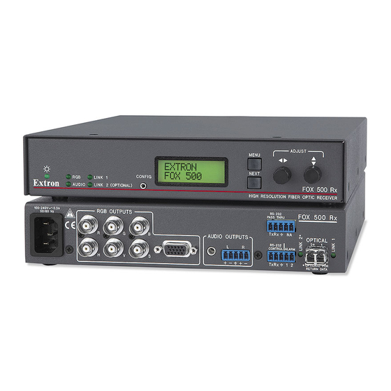
N The FOX 500 consists of a transmitter (FOX 500 Tx) and a receiver (FOX 500 Rx) with one or two
fiberoptic cables linking the two units.
N The analog RGB input signal is digitized pixel for pixel in the transmitter, sent digitally through the
fibercable, and converted back to analog RGB in the receiver.
N The analog audio signal(s) is (are) digitized in the transmitter, sent through the fiber cable, and
converted back to analog audio in the receiver.
Optical fiber interconnection between transmitter and receiver
Number/type �������������������������������� 1 or 2 fiber optic
N Only one fiber is required to transmit video, audio, and unidirectional data. A second fiber is
required to transmit return data for bidirectional control/communication.
Connectors ������������������������������������� 2 LC connectors
Operating distance
Singlemode ������������������������� 30 km (18�75 miles) with singlemode (SM) cables with a FOX 500 SM
Multimode �������������������������� 300 m (985') with 62�5 µm multimode (MM) cables with a FOX 500 MM
N Operating distance is approximate. These are typical maximum distances that may vary depending
on factors such as fiber type, fiber bandwidth, connector splicing, losses, modal or chromatic
dispersion, environmental factors, and kinks.
Nominal peak wavelength����������� 850 nm for FOX 500 MM, 1310 nm for FOX 500 SM
Data rate ����������������������������������������� 4�25 Gbps
Transmission power
Singlemode ������������������������� -5 dBm, typical
Multimode �������������������������� -5 dBm, typical
Maximum receiver sensitivity
Singlemode ������������������������� -18 dBm, typical
Multimode �������������������������� -12 dBm, typical
Optical loss budget
Singlemode ������������������������� 13 dB, maximum
Multimode �������������������������� 7 dB, maximum
Video
Number/signal type ��������������������� 1 VGA-UXGA RGBHV, RGBS, RGsB, RsGsBs input
Gain ������������������������������������������������� Unity
Pixel data bit depth ����������������������� 8 bits per channel, 3 channels (R, G, B)
Maximum resolution �������������������� 1600x1200 @ 60 Hz, digitized pixel for pixel; higher resolutions up to
Video input and loop-through — transmitter(FOX 500 Tx)
Number/signal type ��������������������� 1 VGA-UXGA RGBHV, RGBS, RGsB, RsGsBs input
Connectors ������������������������������������� 1 x 5 female BNC or (1) female 15-pin HD for input
Nominal level �������������������������������� 0�7 Vp-p for RGB
Minimum/maximum levels �������� Analog: 0�3 V to 1�5 Vp-p with no offset
Impedance �������������������������������������� 75 ohms
Horizontal frequency �������������������� 24 kHz to 100 kHz
Vertical frequency �������������������������� 40 Hz to 120 Hz
Return loss �������������������������������������� <-40 dB @ 5 MHz
N These transceivers are class 1 laser products. They meet the safety regulations of IEC-60825, FDA
21, CFR 1040.10, and FDA 21 CFR 1040.11.
Extron FOX 500 Tx, FOX 500 Rx Fiber Optic Transmitter-Receiver Pair • Specifications
1 km (3280') with 50 µm multimode (MM) cables with a FOX 500 MM
2 km (6561') with 50 µm 2000 MHz bandwidth laser optimized multimode
cable with a FOX 500 MM
1 VGA-UXGA RGBHV, RGBS, RGsB, RsGsBs loop-through
2048x1120, undersampled
1 VGA-UXGA RGBHV, RGBS, RGsB, RsGsBs loop-through
(1) female 15-pin HD for loop-through
1
Advertisement
Table of Contents

Related Manuals for Extron electronics Fiber Optic Transmitter-Receiver Pair FOX 500 Rx


Summary of Contents for Extron electronics Fiber Optic Transmitter-Receiver Pair FOX 500 Rx
- Page 1 Specifications — FOX 500 N The FOX 500 consists of a transmitter (FOX 500 Tx) and a receiver (FOX 500 Rx) with one or two fiberoptic cables linking the two units. N The analog RGB input signal is digitized pixel for pixel in the transmitter, sent digitally through the fibercable, and converted back to analog RGB in the receiver.
- Page 2 Specifications — FOX 500, cont’d Video output — receiver(FOX 500 Rx) Number/signal type ��������������������� 2 VGA-UXGA RGBHV, RGBS, RGsB, RsGsBs (follows input or can be set by Connectors ������������������������������������� 1 x 6 female BNC and (1) female 15-pin HD Nominal level �������������������������������� 0�7 Vp-p for RGB Minimum/maximum levels ��������...
-
Page 3: Regulatory Compliance
Maximum level (600 ohm) ����������� >+15 dBm, unbalanced at 1% THD+N Audio delay ����������������������������������� 1�5 frames Control/remote Serial control ports on each unit (transmitter and receiver) Control �������������������������������� 1 RS-232, 3�5 mm captive screw connector, 5 pole (3 pins are used) (rear panel) 1 RS-232, 2�5 mm mini stereo jack (front panel) Pass-through ����������������������...
Need help?
Do you have a question about the Fiber Optic Transmitter-Receiver Pair FOX 500 Rx and is the answer not in the manual?
Questions and answers