Sign In
Upload
Manuals
Brands
IEI Technology Manuals
Touch Panel
UPC-V315-QM77
IEI Technology UPC-V315-QM77 Manuals
Manuals and User Guides for IEI Technology UPC-V315-QM77. We have
1
IEI Technology UPC-V315-QM77 manual available for free PDF download: User Manual
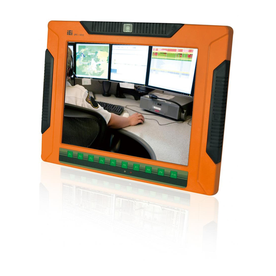
IEI Technology UPC-V315-QM77 User Manual (145 pages)
Panel PC with Touch Screen and Intel Core i3-3217UE/ i7-3517UE Processor, GbE, Wireles s , USB, Audio, RS-232/422/485, RoHS Compliant, IP 65 Protection
Brand:
IEI Technology
| Category:
Touch Panel
| Size: 4 MB
Table of Contents
Table of Contents
4
Introduction
13
Figure 1-1: UPC-V315-QM77 Panel PC
14
Overview
14
External Overview
15
Front Panel
15
LED Indicators
16
Bottom Panel
18
Features
15
Model Variations
15
Figure 1-2: Front View
16
Figure 1-3: LED Indicators
17
Table 1-1: LED Indicators
18
Side Panels
19
Figure 1-4: Bottom View
19
Figure 1-5: Left Side View
19
Frame (Function Keys)
20
Rear Panel
20
Figure 1-6: Right Side View
20
Figure 1-7: Rear View
20
Table 1-2: Function Keys
21
Figure 1-8: Function Key Locations
21
Dimensions
22
Figure 1-9: UPC-V315-QM77 Dimensions (MM)
22
Specifications
23
Table 1-3: System Specifications
25
2 Unpacking
26
Unpacking
27
Packing List
28
3 Installation
30
Anti - Static Precautions
31
Installation Precautions
31
Preinstalled Components
32
Ssd Installation
32
Figure 3-2: Inserting the SSD
33
Figure 3-1: Remove the SSD Drive Bay Access Panel
33
Figure 3-3: Securing the SSD
34
Figure 3-4: SSD Installation
34
Figure 3-5: VESA Mount Retention Screw Holes
35
Wall Mounting
36
Figure 3-9: Secure the Panel PC
39
Figure 3-10: I/O Cover Retention Screws
40
Figure 3-11: External Peripheral Device Connection
40
Figure 3-12: Rubber Gasket Removal
40
ACC Mode Selection
41
AT/ATX Power Mode Selection
41
Figure 3-13: Rubber Gasket and Cable
41
Figure 3-14: External Peripheral Device Connection Complete
41
Figure 3-15: ACC Mode Switch
41
Audio Connectors
42
CAN-Bus Terminal Block
42
Figure 3-16: AT/ATX Power Mode Switch
42
Figure 3-17: CAN-Bus Terminal Block Pinouts
42
HDMI Connector
42
Figure 3-18: HDMI Connection
43
Table 3-1: HDMI Pinouts
43
Figure 3-19: LAN Connection
44
Figure 3-20: RJ-45 Ethernet Connector
44
LAN Connector
44
Figure 3-21: 3-Pin Terminal Block Pinouts
45
Power Input, 3-Pin Terminal Block
45
Power Input, 4-Pin DIN Connector
45
Table 3-2: LAN Pinouts
45
Table 3-3: RJ-45 Ethernet Connector Leds
45
Figure 3-23: RJ-45 RS-232 Serial Port Pinout Location
46
Figure 3-24: DB-9 Connector Pinout Location
46
RS-232 Serial Port
46
Figure 3-6: Mounting Brackets (Side Panels)
36
Figure 3-7: Wall-Mounting Bracket
37
Figure 3-8: Chassis Support Screws
38
Bottom Panel Connectors
39
External Peripheral Device Connection
39
Mounting the System
35
Figure 3-22: Power Input Connector
46
Table 3-5: DB-9 Connector Pinouts
47
Figure 3-25: RJ-45 RS-232 Serial Device Connection
47
Table 3-7: DB-9 Connector Pinouts
48
Table 3-6: RJ-45 RS-422/485 Serial Port Pinouts
48
Figure 3-28: RJ-45 RS-422/485 Serial Device Connection
49
USB Connectors
49
Figure 3-29: USB Device Connection
50
Table 3-8: USB Port Pinouts (USB 2.0)
50
Table 3-10: VGA Connector Pinouts
51
Figure 3-31: VGA Connector
52
Figure 3-32: Power Connectors
53
Redundant Power
53
Acc on
54
Boot-Up
54
Figure 3-33: ACC On: at Mode
54
Figure 3-34: ACC On: ATX Mode
54
Figure 3-35: ACC On: Switch between PWR1 and PWR2
55
Shutdown
55
Switch to Backup Power
55
Acc off
56
Boot-Up
56
Figure 3-36: ACC On: Shutdown
56
Figure 3-37: ACC Off: at Mode
57
Figure 3-38: ACC Off: ATX Mode
57
Figure 3-39: ACC Off: Switch between PWR1 and PWR2
57
Switch to Backup Power
57
Figure 3-40: ACC Off: Shutdown
58
Shutdown
58
Figure 3-41: Remote Control
59
Remote Control
59
Bios
60
Figure 3-30: VGA Connector
51
Table 3-9: USB Port Pinouts (USB 3.0)
51
VGA Connector
51
Table 3-4: RJ-45 RS-232 Serial Port Pinouts
46
Figure 3-27: DB-9 Connector Pinout Location
48
Figure 3-26: RJ-45 RS-422/485 Serial Port Pinout Location
48
RS-422/485 Serial Port
48
4 Bios
61
Introduction
61
Starting Setup
61
Using Setup
61
Getting Help
62
Unable to Reboot after Configuration Changes
62
BIOS Menu Bar
62
Table 4-1: BIOS Navigation Keys
62
Main
63
Advanced
64
ACPI Settings
65
RTC Wake Settings
66
CPU Configuration
67
SATA Configuration
69
Intel(R) Rapid Start Technology
69
USB Configuration
70
F81866 Super IO Configuration
71
Serial Port N Configuration
72
H/W Monitor
75
Serial Port Console Redirection
76
Iei Feature
78
Chipset
80
PCH-IO Configuration
81
PCH Azalia Configuration
82
System Agent (SA) Configuration
83
Graphics Configuration
83
NB Pcie Configuration
86
Memory Configuration
87
Boot
88
Security
90
Save & Exit
91
A Bios Menu Options
93
B One Key Recovery
96
B.1 O Ne K Ey R Ecovery I Ntroduction
97
Figure B-1: IEI One Key Recovery Tool Menu
97
One Key Recovery Introduction
97
System Requirement
98
Supported Operating System
99
B.2 S Etup P Rocedure for W Indows
100
Setup Procedure for Windows
100
Create Partitions
101
Hardware and BIOS Setup
101
Figure B-3: Recovery Tool Setup Menu
102
Figure B-2: Launching the Recovery Tool
102
Figure B-6: Launching the Recovery Tool
106
Figure B-7: Manual Recovery Environment for Windows
106
Figure B-8: Building the Recovery Partition
107
Figure B-9: Press any Key to Continue
107
Create Factory Default Image
108
Auto Recovery Setup Procedure
113
Figure B-4: Command Prompt
103
Figure B-5: Partition Creation Commands
104
Install Operating System, Drivers and Applications
105
Building the Recovery Partition
106
Figure B-11: Recovery Tool Menu
108
Figure B-12: about Symantec Ghost Window
109
Figure B-14: Select a Local Source Drive
110
Figure B-22: Auto Recovery Utility
114
Figure B-24: Auto Recovery Environment for Windows
114
Figure B-25: Building the Auto Recovery Partition
115
Figure B-26: Factory Default Image Confirmation
115
Figure B-29: Partitions for Linux
118
Figure B-30: Manual Recovery Environment for Linux
119
Figure B-31: Access Menu.lst in Linux (Text Mode)
120
Figure B-32: Recovery Tool Menu
120
B.5 R Ecovery T Ool F Unctions
121
Figure B-33: Recovery Tool Main Menu
121
Recovery Tool Functions
121
Factory Restore
122
Figure B-34: Restore Factory Default
122
Backup System
123
Figure B-35: Recovery Complete Window
123
Figure B-36: Backup System
123
Figure B-37: System Backup Complete Window
124
Figure B-38: Restore Backup
124
Restore Your Last Backup
124
Figure B-39: Restore System Backup Complete Window
125
Figure B-40: Symantec Ghost Window
125
Manual
125
B.6 R Estore S Ystems from a L Inux S Erver through Lan
126
Restore Systems from a Linux Server through Lan
126
Configure DHCP Server Settings
127
Configure TFTP Settings
128
Configure One Key Recovery Server Settings
129
Create Shared Directory
130
Start the DHCP, TFTP and HTTP
130
Setup a Client System for Auto Recovery
131
B.7 O Ther I Nformation
134
Other Information
134
Using AHCI Mode or Ali M5283 / VIA VT6421A Controller
134
System Memory Requirement
136
Figure B-10: Press F3 to Boot into Recovery Mode
108
Figure B-15: Select a Source Partition from Basic Drive
110
Figure B-23: Launching the Recovery Tool
114
Figure B-28: Press any Key to Continue
116
Figure B-27: Image Creation Complete
116
B.4 S Etup P Rocedure for L Inux
117
Setup Procedure for Linux
117
Figure B-13: Symantec Ghost Path
109
Figure B-16: File Name to Copy Image to
111
Figure B-17: Compress Image
111
Figure B-18: Image Creation Confirmation
112
Figure B-20: Image Creation Complete
112
Figure B-19: Image Creation Complete
112
B.3 a Uto R Ecovery S Etup P Rocedure
113
Figure B-21: Press any Key to Continue
113
C Safety Precautions
137
Safety Precautions
138
General Safety Precautions
138
C.1 S Afety P Recautions
138
Anti-Static Precautions
139
Product Disposal
139
Maintenance and Cleaning Precautions
140
Maintenance and Cleaning
140
C.2 M Aintenance and C Leaning P Recautions
140
Cleaning Tools
141
D Hazardous Materials Disclosure
142
Hazardous Material Disclosure Table for Ipb Products Certified as R Ohs Compliant under 2002/95/Ec Without Mercury
143
D.1 H Azardous M Aterial D Isclosure T Able for Ipb P Roducts C Ertified as R O Hs C Ompliant U Nder 2002/95/Ec W Ithout M Ercury
143
Advertisement
Advertisement
Related Products
IEI Technology UPC-12A/GM45
IEI Technology UPC-F12C-ULT3
IEI Technology UPC-F12M1-RPLP
IEI Technology UPC-V312-D525
IEI Technology uIBX-200-VX800
IEI Technology uIBX-230-BT Series
IEI Technology uIBX-210-CV-N2600 Series
IEI Technology uSmart3400
IEI Technology uIBX-260-EHL Series
IEI Technology 210UPC-V312
IEI Technology Categories
Motherboard
Touch Panel
Computer Hardware
Single board computers
Desktop
More IEI Technology Manuals
Login
Sign In
OR
Sign in with Facebook
Sign in with Google
Upload manual
Upload from disk
Upload from URL