Kärcher CV 66/2 Service Manual
Upright brush-type
Hide thumbs
Also See for CV 66/2:
- Instruction manual (148 pages) ,
- Manual (8 pages) ,
- Original instructions manual (172 pages)
Table of Contents
Advertisement
Advertisement
Table of Contents

Related Manuals for Kärcher CV 66/2


Summary of Contents for Kärcher CV 66/2
- Page 1 CV 66/2 Service Manual 5.906-479.0 Rev 00 01/09 English...
-
Page 2: Table Of Contents
Contents Safety instructions Hazard levels Technical Features Operation and control Vacuuming Electrical system Setup and function Appliance view View from below Basic settings and service procedures General information Remove operating panel Replacing the mains cable Replace appliance switch Replace wire harness Removing the handle Removing the appliance hood Replacing the drive belt of the brush roller... -
Page 3: Safety Instructions
Preface Safety instructions Good servicing requires detailed and practice-oriented training Hazard levels as well as good well-structured training materials. Hence we offer regular basic and advanced training programmes Danger covering the entire product range for all service engineers. Immediate danger that can cause severe injury or even death. In addition to this, we also prepare service manuals for important appliances - these can be initially used as instruction guides and Technical Features... -
Page 4: Setup And Function
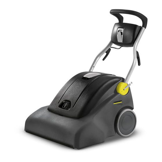
Setup and function Appliance view 1 Pushing handle, adjustable 2 Cable clamp 3 Cable holder, rotating 4 Storage compartment 5 Lock of pushing handle 6 Lid of filter chamber 7 Suction hose connection (for optional suction set) 8 Fuse for brush drive 9 Fuse for suction turbine 10 Display 'Filter bag is full' 11 Power switch... -
Page 5: Remove Operating Panel
Remove operating panel The operating panel includes the appliance switch, the fuses for the brush motor and the suction turbines and the ring core throt- tles. The operating panel is connected to the appliance via a har- ness, which is routed along the right handlebar. Separate the protective conductor from the grounding clip. -
Page 6: Replace Wire Harness
Remove the handle and the handlebars (see "Removing the handle") Restore cable connections. Contact arrangement: Pull the wire harness out of the column Disconnect the connectors in the appliance Route a new wire harness Restore the connections Reassemble the handle and the operating panel Removing the handle The handle must be removed in order to be able to remove the appliance hood. -
Page 7: Removing The Appliance Hood
To change a broken height adjustment lever, you must proceed Unscrew the screw from the wheel shaft as described above. Removing the wheel Turn the lever by 90° and pull it out to remove the lever from the plastic cover Replace the splint after removing it Assemble the handle and the adjustment in reverse order of removal... - Page 8 Disconnect the connector on the pressure switch Disconnect the cables of the brush motor at the connectors Do not remove the pressure switch Tilt appliance back Remove the cover with filter basket Unscrew the fastening screw at the top of the frame Slide the wire harness into the appliance sot that it will not be Unscrew the screws on the hinge (increased force: The pinched when the hood is lifted...
-
Page 9: Replacing The Drive Belt Of The Brush Roller
Position of the support strut - appliance hood removed for clarity. Remove cover Loosen the screws on the support plate of the brush motor - do not remove all the way Slide the support plate up to relax the drive belt Open the fastening screws of the strut on both sides. -
Page 10: Clean/Replace The Suction Channel
Clean/replace the suction channel There is a suction channel cover on the brush head. This channel can be removed to clean the suction channel. Remove the appliance cover Position of the drive belt - display with removed appliance hood. Loosen the screw on the support plate Slide the support plate down to tension the drive belt Loosen all 8 screws on the suction channel cover Make sure you slide the support plate straight - do not tilt... -
Page 11: Replacing The Brush Rollers
5.10 Replacing the brush rollers 5.11 Replace the toothed belt in the brush head gear The brush rollers must be replaced when the brush length has There is a toothed belt in the gears of the brush head, which must reached its tear indication. -
Page 12: Replace Suction Turbine
5.12 Replace suction turbine The suction turbine consists of 2 turbine motors in a casing. The turbine unit must be completely replaced. Remove the cover with filter basket Remove the turbine unit from the rubber tub Guide the cable through the opening Do not damage the rubber tub Install the new turbine unit in reverse order. -
Page 13: Remove The Height Adjustment Of The Brush Head
Remove the bushing and the spacer disc Tilt out the spring holder and pull out toward the bottom. Pull the brush head toward the front Assembly in reverse order Installation in reserve order 5.15 Remove the microswitch of the brush motor 5.14 Remove the height adjustment of the brush head The brush motor is switched off as soon as a suction hose is in-... -
Page 14: Replace The Pressure Switch
Remove the Y piece Replace the safety plate The pressure switch is located in the center of the turbine tub Remove the nut and seal of the pressure switch Tilt the appliance backwards and remove the brush motor Reinstall the Y piece - this might require increased force. Screw in the Y piece 5.16 Replace the pressure switch Remove the brush motor from the appliance... -
Page 15: Troubleshooting
Install brush motor - watch for drive belt! Install turbine filter cover Troubleshooting Fault Remedy Appliance cannot be started Establish mains contact. Check the mains connection cable for damages. Replace the defective mains cable. Check/replace the startup capacitor. Check/replace the startup capacitor startup electronics. Check/replace switch "brush drive". -
Page 16: Technical Specifications
Technical specifications Electrical connection Voltage, EU 220...240 Frequency 50 - 60 Average power consumption 1350 Maximum power consumption 1550 Blower data Power 2 x 570 Max. power 2 x 650 Under-pressure 14,3 Air quantity 2 x 52 Brush Power Max. power Drive Gear belt Working width... - Page 17 Description / Use Tightening torque (Nm) 4x M 8x16 / push handle attachment, left, with gear housing Plastic screws 3x 5x20 / screw connection pump lid Plastic screws 7x 5x20 / turbine housing Plastic screws 6x 5x20 / sheet metal, brush bearing Plastic screws 6x 5x20 / gear housing with brush housing Plastic screws 8x 5x20 / running gear Plastic screws 2x 5x20 / suction channel cover...
Need help?
Do you have a question about the CV 66/2 and is the answer not in the manual?
Questions and answers