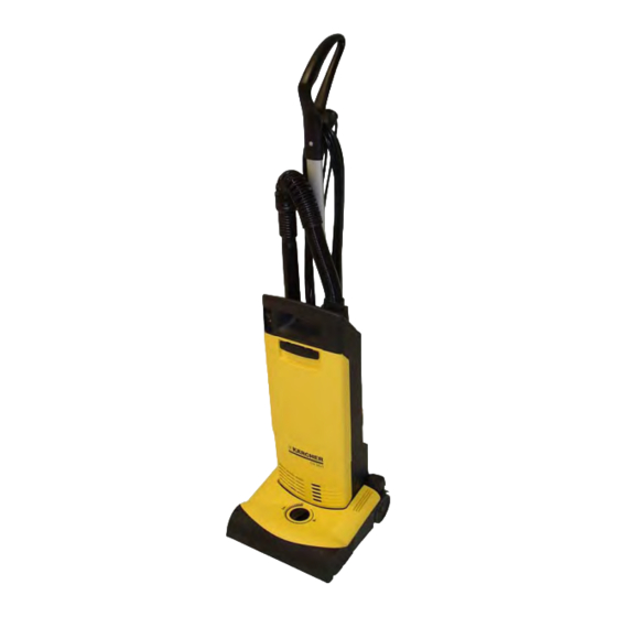
Kärcher CV 30/1 Unit Information
Hide thumbs
Also See for CV 30/1:
- Manual (196 pages) ,
- Operating instructions manual (152 pages) ,
- User manual (25 pages)

Related Manuals for Kärcher CV 30/1


Summary of Contents for Kärcher CV 30/1
- Page 1 New Unit Information CV 30/1 CV 38/1 1.023-... 1.435-... New Unit Information 02.2004 5.905-938...
- Page 2 – Protective motor filter – Exhaust air filter – Filter full display. – CV 30/1, working width 300 mm (11.8 in) – CV 38/1, working width 380 mm (14.9 in) Drive unit – Suction motor drives the brush roller via two toothed belts.
-
Page 3: View From The Front
CV 30/1, CV 38/1 Unit functions View from the front 1 Handle 8 Brush head cover 2 Cable hook, top 9 Dust filter cover 3 Mains connection cable 10 Cover latch 4 Foot lever, brush head unlocking device 11 Unit switch... - Page 4 Unit functions CV 30/1, CV 38/1 View from the front, opened dust filter cover 1 Retaining lever for dust filter Note: 2 Dust filter (felt filter) The dust filter (2) and the protective motor 3 Retaining lever for protective motor filter...
-
Page 5: Rear View
CV 30/1, CV 38/1 Unit functions Rear view 1 Handle 9 Foot lever, brush head unlocking device 2 Suction hose 10 Upholstery nozzle (accessories) 3 Top cover 11 Rear cover 4 Lower cable hook 12 Crevice tool (accessories) 5 Clamping lever for handle height... - Page 6 Unit functions CV 30/1, CV 38/1 Rear view, rear cover 1 Handle column Note: 2 Retaining screws for rear cover (4x) The clamping lever (4) and the lower cable 3 Rear cover hook (5) can be replaced once the rear cover 4 Clamping lever for handle height (3) has been removed.
-
Page 7: View From Above
CV 30/1, CV 38/1 Unit functions View from above 1 Top cover 2 Retaining screws for upper cover (2x) 3 Control lamp (red), filter status 4 Mains connection cable 5 Circlip 6 Suction hose connection New Unit Information 02.2004 Page 7 / 25... - Page 8 Unit functions CV 30/1, CV 38/1 Upper cover open 1 Top cover 2 Unit switch 3 Unit switch connections 4 Control lamp, filter status 5 Housing for control printed circuit board 6 Earth connection plug 7 Mains connection cable 8 Suction hose connection...
-
Page 9: Mains Connection Cable
CV 30/1, CV 38/1 Unit functions Mains connection cable 1 Unit switch Replace the mains connection cable 2 Control lamp, filter status – Pull the connection plug (5) off the unit switch 3 Housing for control printed circuit board (1). -
Page 10: Printed Circuit Board
Unit functions CV 30/1, CV 38/1 Printed circuit board Replace the printed circuit board When installing the printed circuit board with housing (2) ensure that the vacuum hose (6) is correctly pushed onto the connection (7). The vacuum sensor on the printed circuit board measures the vacuum in the suction system. - Page 11 CV 30/1, CV 38/1 Unit functions Brush head, view from below Removing skid plate 1 Brush roller 2 Locking pin (3x) for skid plate – Rotate the locking pins (2) through 90° in an counter-clockwise direction. 3 Skid plate 4 Roller –...
- Page 12 Unit functions CV 30/1, CV 38/1 Brush head, view from below 1 Brush roller drive Replace the brush roller 2 Brush roller drive belt – Remove the retaining screws (6) for the 3 Retaining screws (8x) for brush head counter bearing (7).
-
Page 13: Brush Head
CV 30/1, CV 38/1 Unit functions Brush head 1 Driving gear Remove brush head cover 2 Centrifugal clutch drive belt – Remove the retaining screws (Item 3, 3 Centrifugal clutch page 12). 4 Brush roller drive belt – Remove the brush head cover (5). - Page 14 Unit functions CV 30/1, CV 38/1 Brush head 1 Driving gear Dismantle the suction motor 2 Suction motor housing – Pull the drive belt (5) off the driving gear (1). 3 Foot lever, brush head unlocking device – Remove the suction motor housing (2) from 4 Bearing shells for suction motor housing the bearing shells (4).
- Page 15 CV 30/1, CV 38/1 Unit functions Brush head 1 Drive belt for centrifugal clutch Remove the centrifugal clutch 2 Centrifugal clutch – Take out the centrifugal clutch (2). 3 Brush roller drive belt – Remove the drive belts (1, 3).
- Page 16 Unit functions CV 30/1, CV 38/1 Brush head Height adjustment, brush head disassem- bled 1 Opening for running wheel, height adjustment 2 Brush head housing 3 Steel spring 4 Running wheel cover 5 Running wheel, height adjustment 6 Rotary knob...
- Page 17 CV 30/1, CV 38/1 Unit functions Suction motor 1 Retaining screw (4x) for upper section of housing 2 Lower section of housing 3 Suction motor driving gear 4 Upper housing section New Unit Information 02.2004 Page 17 / 25...
- Page 18 Unit functions CV 30/1, CV 38/1 Suction motor 1 Lower section of housing Dismantle upper housing section 2 Mains connection cable – Remove the retaining screws (Item 1, 3 Spring clip for bearing shell page 17). 4 Terminal strip/connection for suction –...
- Page 19 CV 30/1, CV 38/1 Unit functions Suction motor 1 Connection cable Replace the suction motor 2 Driving gear – Disconnect the connection cable (1) from the 3 Hexagon nut M5 terminal strip (4). 4 Terminal strip/connection for suction - Remove the suction motor (5).
- Page 20 Unit functions CV 30/1, CV 38/1 Suction motor 1 Lower section of housing Insert mains connection cable 2 Mains connection cable for suction motor The mains connection cable (2) must be laid inside the pins provided (see arrow) as shown in the figure above.
- Page 21 CV 30/1, CV 38/1 Unit functions Suction motor 1 Mains connection cable Insert mains connection cable 2 Lower section of housing The length of the mains connection cable (1), measured from the upper edge of the lower 3 Suction motor housing section (2), must be 14 cm (5.5 in).
- Page 22 Unit functions CV 30/1, CV 38/1 Suction motor 1 Suction motor Replace seal. 2 Lower section of housing The seal (3) must be placed exactly in the guide groove of the lower housing section (2) to protect 3 Seal (marked in red) the suction motor (1) from dust and dirt.
- Page 23 CV 30/1, CV 38/1 Unit functions Suction motor 1 Carbon brush (2x) Open the suction motor housing 2 Suction motor – Remove the motor cover (4) from the 3 Hard rubber bracket protective motor housing (5). 4 Motor cover – The suction motor (2) can now be removed 5 Protective motor housing from the protective motor housing (5).
-
Page 24: Troubleshooting
Troubleshooting CV 30/1, CV 38/1 Troubleshooting Fault Solution Motor not running – Check cable, plug, fuse and socket. – Thermal contact has switched off the suction motor because of overheating, leave the suction motor to cool. Clattering noise when – The centrifugal clutch has triggered, check brush for switched off blocking objects and remove them. -
Page 25: Technical Specifications
CV 30/1, CV 38/1 Technical specifications Technical specifications Unit Type Unit No. Circuit Operating Spare parts diagram instructions list CV 30/1 EU 1.023-101 0.088-614 5.960-522 5.970-067 (220-240 Volt / 50-60 Hz) CV 38/1 EU 1.435-101 0.088-614 5.960-522 5.970-067 (220-240 Volt / 50-60 Hz) CV 30/1 USA 1.023-105...
Need help?
Do you have a question about the CV 30/1 and is the answer not in the manual?
Questions and answers