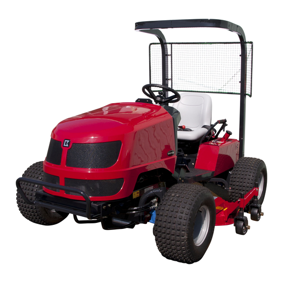
Baroness GM1700 Owner's Operating Manual
3-unit mid-mount rotary mower
Hide thumbs
Also See for GM1700:
- Service manual (192 pages) ,
- Owner's operating manual (87 pages) ,
- Owner's operating manual (43 pages)
Table of Contents
Advertisement
Quick Links
Download this manual
See also:
Service Manual
Advertisement
Chapters
Table of Contents

Subscribe to Our Youtube Channel
Related Manuals for Baroness GM1700


Summary of Contents for Baroness GM1700
- Page 1 3-Unit Mid-Mount Rotary Mower Owner's operating manual "Required reading" Read this manual and the owner's manual for the engine before using the machine. Serial No.10038- Original Instructions Ver.1.0...
- Page 2 GM1700 Greeting Thank you for purchasing the Baroness machine. This manual explains proper handling, adjustment, and inspection of your machine. Prior to use, carefully read this manual to thoroughly understand the contents for safe and correct operation. We hope you will use the machine safely, and take advantage of its best performance.
- Page 3 The information described in this manual is subject to change for improvement without prior notice. When replacing parts, be sure to use genuine Baroness parts or parts designated by Kyoeisha. Note that the Baroness product warranty may not apply to defects caused by the use of parts from other companies.
- Page 4 GM1700 Introduction Purpose This machine is intended for cutting turf grass at golf courses. Do not use this machine in any way other than its intended purpose, and do not modify the machine. Operating this machine for other purposes and modifying it may be very dangerous and may cause damage to the machine.
-
Page 5: Table Of Contents
GM1700 Contents Safety............... Page 1-1 Safe Operating Practices........Page 1-2 Disposal............Page 2-1 Waste Disposal..........Page 2-2 Product Overview........... Page 3-1 Specifications..........Page 3-2 Sound pressure level........Page 3-3 Sound power level.......... Page 3-3 Vibration level..........Page 3-3 Names of Each Section........Page 3-4 Safety Signs and Instruction Signs.... - Page 6 GM1700 Contents...
-
Page 7: Safety
GM1700 Safety Safe Operating Practices....... Page 1-2 Training...........Page 1-2 Preparation..........Page 1-2 Operation..........Page 1-3 Maintenance and storage....... Page 1-4 Page 1-1... -
Page 8: Safe Operating Practices
GM1700 Safety Failure to adequately follow these safety Lack of awareness of the effect of precautions may cause an accident resulting in ground conditions, especially slopes injury or death. Incorrect hitching and load distribution Never allow children or people unfamiliar... - Page 9 GM1700 Safety If fuel is spilled, do not attempt to start the Stay alert for humps and hollows and engine but move the machine away from other hidden hazards. the area of spillage and avoid creating any Never operate across the face of the...
- Page 10 GM1700 Safety Look behind and down before backing up to When machine is to be parked, stored, or left be sure of a clear path. unattended, lower the cutting units unless a positive mechanical lock is provided. Do not carry passengers.
- Page 11 GM1700 Safety Disconnect battery before making any repairs. Disconnect the negative terminal first and the positive last. Reconnect positive first and negative last. Make sure that parts such as wires are not touching each other and that their covers have not come off.
- Page 12 GM1700 Safety Page 1-6 Safe Operating Practices...
-
Page 13: Disposal
GM1700 Disposal Waste Disposal........Page 2-2 About the Waste disposal....... Page 2-2 Page 2-1... -
Page 14: Waste Disposal
GM1700 Disposal Waste Disposal About the Waste disposal Make sure that waste generated when servicing or repairing the machine is disposed of in accordance with local regulations. (e.g. waste oil, antifreeze batteries, rubber products, and wires etc.) Page 2-2 Waste Disposal... -
Page 15: Product Overview
GM1700 Product Overview Specifications......... Page 3-2 Specifications..........Page 3-2 Sound pressure level......Page 3-3 Sound pressure level......Page 3-3 Sound power level........Page 3-3 Sound power level........Page 3-3 Vibration level......... Page 3-3 Hand-arm vibration......... Page 3-3 Whole body vibration......Page 3-3 Names of Each Section...... -
Page 16: Specifications
GM1700 Product Overview Specifications Specifications Model GM1700 Total length 255 cm Total width 159 cm Dimensions Roof 197 cm Total height Handle 121 cm Weight 743 kg Minimum turning radius 298 cm Model Kubota D1105 Type Vertical water-cooled 4-cycle diesel engine... -
Page 17: Sound Pressure Level
GM1700 Product Overview Sound pressure level Sound pressure level This machine was confirmed to have a continuous A-weighted sound pressure level of 93 dB by measuring identical machines in accordance with the procedure specified in ISO5395-1:2013. Sound power level Sound power level... -
Page 18: Names Of Each Section
GM1700 Product Overview Serial Number Plate Names of Each Section The serial number plate indicates the name and serial number of the machine. 4ogipb-001 Serial Number Plate_001 Specification Decal The Specification decal indicates the CE logo, model name, and weight, etc. -
Page 19: Year Of Manufacture Decal
GM1700 Product Overview Year of Manufacture Decal The year of manufacture decal indicates the year when this machine was manufactured. YEAR OF MANUFACTURE wvzv36-001 Year of Manufacture Decal_001 ROPS compliance decal ROPS compliance decal indicates the manufacturer of the fitted machine, the model, etc. -
Page 20: Safety Signs And Instruction Signs
6iul4h-015 Positions of Safety Decals and Instruction Decals_002 Part numbers for decals that need to be replaced are listed in the parts catalog. Order them from a Baroness dealer or Kyoeisha. Positions of Safety Decals and Instruction Decals 6iul4h-016... -
Page 21: Safety Signs And Instruction Signs
GM1700 Product Overview Warning and Instruction Decals K4205001540 Decal, caution for high temperature Caution High temperature - Do not touch. Otherwise, you will be K 4 2 0 5 0 0 1 5 4 0 burned. qigqnx-022 K4209001000 Diesel fuel filler icon Use No. - Page 22 GM1700 Product Overview K4205001920 Decal, caution for high temperature Caution High temperature - Do not touch. Otherwise, you will be burned. qigqnx-042 K4209000980 Hydraulic oil icon Read the Owner's Operating Manual. K 4 2 0 9 0 0 0 9 8 0...
-
Page 23: Handling Instructions
GM1700 Handling Instructions Pre-installation Adjustments....Page 4-2 Brake Pedal.......... Page 4-25 Parking Brake Lever......Page 4-25 Operating Attachments......Page 4-2 Hood............. Page 4-26 Installation of Universal Joint....Page 4-2 Rear Cover........... Page 4-26 Inspection Before Use......Page 4-2 Center Cover........Page 4-27 Seatback Cover........ -
Page 24: Pre-Installation Adjustments
GM1700 Handling Instructions Pre-installation Adjustments Inspection Before Use Operating Attachments Be sure to perform an inspection before you start using the machine so that you will be able For details on handling the attachment, please to take advantage of its optimum performance refer to the separate attachment's Operating for a long period of time. -
Page 25: Radiator
GM1700 Handling Instructions Pull the dust screen up to remove it. Hood Rubber catch Intake Bolt Radiator Inspection of Radiator For details on handling the engine, please refer to the separate Engine Operating va4j43-003 Manual. Cleaning of Radiator_001 Make sure that there is no damage to the Hood radiator. - Page 26 GM1700 Handling Instructions Important Caution When you supply coolant, be sure to use The radiator cap is pressurized. clean water, such as tap water. If you remove the radiator cap while the During winter, remove coolant. Alternatively, engine is overheated, hot steam will burst out, mix long-life coolant and clean water, and possibly resulting in burns.
-
Page 27: Hydraulic Oil
GM1700 Handling Instructions Open the reserve tank cap, and then For details on changing coolant, please refer supply clean water up to the "FULL" to the separate Engine Operating Manual. mark. Coolant quantity, including the reserve tank, is approximately 6.0 dm (6.0 L). - Page 28 GM1700 Handling Instructions Hydraulic Oil Supply Change of Hydraulic Oil Important Warning Do not mix different types of oil. When you change the hydraulic oil, be sure to drain it into a bowl and discard it in accordance with local laws and regulations.
-
Page 29: Air Cleaner
GM1700 Handling Instructions Open the tank cap, and then pour new oil Air Cleaner from the fill port until the oil level reaches the middle of the oil gauge on the hydraulic Inspection of Air Cleaner tank. For details on handling the engine, please The hydraulic tank capacity is refer to the separate Engine Handling Manual. - Page 30 GM1700 Handling Instructions Cleaning of Air Cleaner Change of Air Cleaner For details on handling the engine, please For details on handling the engine, please refer to the separate Engine Handling Manual. refer to the separate Engine Operating A contaminated air cleaner element may Manual.
-
Page 31: Battery
GM1700 Handling Instructions Battery Supply of Battery Fluid Inspection of Battery For details on handling the battery, please refer to the separate Battery Instruction For details on handling the battery, please Manual. refer to the separate Battery Instruction Danger Danger Manual. -
Page 32: Brake
GM1700 Handling Instructions Brake Around the Engine Inspection of Brake Inspection of Engine-Associated Parts While traveling, depress the brake pedal For details on handling the engine, please firmly to make sure that the brake is applied refer to the separate Engine Operating effectively. - Page 33 GM1700 Handling Instructions The appropriate oil level should be between Re-place the oil filler cap. the upper and lower limit lines on the gauge. kx9ti-003 Supply of Engine Oil_001 rnr453-004 Oil filler cap Inspection of Engine Oil_002 It will take a while for the supplied engine oil Oil level gauge to descend into the oil pan.
-
Page 34: Fuel
GM1700 Handling Instructions Through the oil filling port, supply new Change of Engine Oil engine oil until the oil reaches a level in between the upper and lower limit lines on For details on handling the engine, please the oil level gauge. -
Page 35: Oil Leakage
GM1700 Handling Instructions Fuel Supply Danger Danger Do not supply fuel above F (FULL) level of the fuel gauge. If you supply too much fuel, it might overflow from the fuel cap when you travel or work on a slope. -
Page 36: Tightening Torques
GM1700 Handling Instructions Tightening torques Standard tightening torques Bolts and Nuts Important A number of bolts are used in each part of this machine. Be sure to re-tighten the bolts and nuts, because they may be loosened at the earlier stage of the use. - Page 37 GM1700 Handling Instructions Heat-treated bolt Strength classification 8.8 Strength classification 10.9 Nominal diameter 10.9 tib3yb-002 tib3yb-003 kgf-cm lb-in kgf-cm lb-in 5 - 7 50.99 - 71.38 44.26 - 61.96 7 - 10 71.38 - 101.97 61.96 - 88.51 8 - 11 81.58 - 112.17...
-
Page 38: Principal Tightening Torques
GM1700 Handling Instructions Principal tightening torques Tightening Torque by Model GM1700_Main body Tighten the following bolts and nuts at the torque specified in the table. For thread locking adhesive, apply a middle strength thread locker (ThreeBond 1322 anaerobic adhesives). Tightening torque... -
Page 39: Adjustment Before Operating
GM1700 Handling Instructions Adjustment of Seat Adjustment Before Operating Use the adjustment lever to adjust the seat Adjustment of Steering Wheel back and forth. Adjust the position according to the Warning operator's body size. Since it is dangerous, do not adjust while The adjustment lever is located beneath the traveling. -
Page 40: Procedure To Start / Stop Engine
GM1700 Handling Instructions Procedure to Start / Stop Engine Important The thermo-start lamp turns off at the Start / Stop of Engine specified time. However, the lamp turning off Procedure to Start Engine is not related to the glow plug generating heat. -
Page 41: Safety Mechanisms
GM1700 Handling Instructions The safety device will be activated and will Caution stop the engine under any of the following Quickly returning the ignition key from the conditions: "START" position to the "ON" position may The operator leaves the seat without ・... -
Page 42: Operation Of Each Section
GM1700 Handling Instructions Operation of Each Section Precautions for Operating the Machine Caution Under any circumstances drive the machine at such a speed that you can stop it immediately for emergencies. Cautions for when You Leave the Machine Caution If the brakes are not sufficiently effective, use the wheel stoppers to secure the machine. - Page 43 GM1700 Handling Instructions Knife rotation/stop icons These indicate positions for rotating and stopping the rotary knife. 1. Rotate 2. Stop 6n6oux-018 Engine speed icons These indicate positions for low and high engine speeds. 1. Low speed 2. High speed 6n6oux-019...
- Page 44 GM1700 Handling Instructions K4203001340 Parking brake decal This shows how to lock and release the parking brake. 1. Locked 2. Released 6n6oux-013 K4203001500 Tilt steering decal This shows the steering tilt directions and how to lock and release the position.
-
Page 45: Throttle Lever
GM1700 Handling Instructions Throttle Lever Mower Unit Up/Down Switch The throttle lever is located in the operation Caution panel and enables you to adjust the engine rpm. Before raising or lowering the mower units, Move the throttle lever toward the rabbit icon... -
Page 46: Knife Rotation Lever
GM1700 Handling Instructions Knife Rotation Lever 2WD/4WD Selector Lever Caution Caution Just before you start cutting work, set the When working on a slope, be sure to use the knife rotation lever to the "ON" position. At all machine in 4WD. -
Page 47: Traveling Pedal
GM1700 Handling Instructions Traveling Pedal Brake Pedal The brake pedal is located in the left foot area. Warning To stop the machine, depress the brake pedal This machine is not authorized as a special all the way firmly. motor vehicle. Do not drive it on public roads. -
Page 48: Hood
GM1700 Handling Instructions To close the hood, release the hood support Hood rod, and then lower the hood slowly. Lock the rubber catch securely. Caution Install the bolt and nut. Do not open the hood in strong winds. Caution Be careful not to pinch your fingers when you open or close the hood. -
Page 49: Center Cover
GM1700 Handling Instructions Center Cover Seatback Cover Note: Caution Follow the same steps to remove the left and Be careful not to pinch your fingers when you right seatback covers. open or close the cover. Bring the seat to the frontmost position. -
Page 50: Instruments
GM1700 Handling Instructions Underseat Cover Instruments Instruments on the Operation Panel Caution Be careful not to pinch your fingers when you open or close the underseat cover. Note: Follow the same steps to remove the left and right underseat covers. -
Page 51: Water Temperature Gauge
GM1700 Handling Instructions Water Temperature Gauge Pilot Lamps The water temperature gauge is located in the Charge Lamp operation panel. The charge lamp is the left pilot lamp located This instrument indicates the water in the operation panel. temperature inside the engine. -
Page 52: Travel Of Machine
GM1700 Handling Instructions Angle Meter Thermo-start Lamp The thermo-start lamp is the middle pilot lamp The angle meter is located in the operation located in the operation panel. panel. When the ignition key is set to the "GLOW" This instrument indicates the angle of the position, it illuminates as the glow plug machine position. -
Page 53: Cutting Work
GM1700 Handling Instructions Apply the parking brake and chock the Shift the throttle lever to the rabbit icon (high wheels. speed) to run the engine at the maximum rpm. Set the 2WD/4WD selector lever to the "2WD" position. Shift the mower unit up/down switch to the "DOWN"... - Page 54 GM1700 Handling Instructions Page 4-32 Transporting...
-
Page 55: Maintenance
GM1700 Maintenance Maintenance Precautions...... Page 5-2 Maintenance Schedule......Page 5-3 Specified Values........Page 5-5 Main Consumable Parts......Page 5-6 Jacking up the machine......Page 5-7 About the Jacking up the machine..Page 5-7 Jack-up Points........Page 5-7 Greasing..........Page 5-9 About Greasing........Page 5-9... -
Page 56: Maintenance Precautions
Use tools appropriate for each maintenance operation. Caution For the safe and best performance of your machine, use Baroness genuine parts for replacement and accessories. Please note that our product warranty may be void if you use non-genuine parts for replacement or accessories. -
Page 57: Maintenance Schedule
GM1700 Maintenance Maintenance Schedule GM1700 Follow the maintenance schedule below. ○・・・Inspect, adjust, supply, clean ●・・・Replace (first time) △・・・Replace Maintenance item Tightening the parts ○ Fuel ○ Air cleaner 8 hrs. Engine oil ○ ● △ (first time) 50 hrs. Engine oil filter ○... - Page 58 GM1700 Maintenance Maintenance item Hydraulic motor oil Power unit oil Transmission oil ○ ● △ Hydraulic hose (moving part) ○ △ Hydraulic hose (fixed part) ○ △ "Replacem Air cleaner ○ △ △ ent of Air Cleaner". Electromagnetic pump filter Fuel strainer ○...
-
Page 59: Specified Values
GM1700 Maintenance Maintenance item Tightening the parts ○ Greasing, oiling ○ V-belt ○ △ Cover ○ Oil leakage ○ Hydraulic hose (moving part) ○ △ Hydraulic hose (fixed part) ○ △ ○ Duct ○ Cleaning the exterior ○ The values for consumables are not guaranteed. -
Page 60: Main Consumable Parts
GM1700 Maintenance Main Consumable Parts Part Name Code Fan belt PF1G345-9701-0 Oil element PF16271-3209-3 Air cleaner element PFT0270-1632-0 Fuel filter element PF1G313-4301-1 Hydraulic cartridge filter K3412000050 Hydraulic oil (20 L can) K2913100200 Brake wire, left K1120182500 Brake wire, right K1120199500... -
Page 61: Jacking Up The Machine
GM1700 Maintenance Jacking up the machine Jack-up Points Front right frame About the Jacking up the machine Front left frame Center of pivot Warning Rear left frame When replacing a tire or beginning any other Rear right frame maintenance or repairs, be sure to chock the Front right frame wheels to prevent the machine from moving. - Page 62 GM1700 Maintenance Rear right frame rwyt62-051 Jack-up Points_005 Rear left frame rwyt62-052 Jack-up Points_006 Page 5-8 Jacking up the machine...
-
Page 63: Greasing
GM1700 Maintenance Greasing No. of Location Greasing About Greasing Points Pivot Since there may be adhesion or damage due Knife rotation lever fulcrum to lack of grease on moving parts, they must be greased. Brake pedal shaft fulcrum Add urea-based No. 2 grease in accordance Chain wheel mounting shaft fulcrum with the Maintenance Schedule. - Page 64 GM1700 Maintenance Front left wheel Chain wheel mounting shaft fulcrum There is one greasing point each on the left and right. 8bq62b-131 Greasing Points_004 8bq62b-134 Knife rotation lever fulcrum Greasing Points_007 Traveling pedal shaft fulcrum Forward pedal 8bq62b-132 Greasing Points_005...
- Page 65 GM1700 Maintenance Brake lever shaft Tension shaft fulcrum There is one greasing point each in the left and right brake areas. 8bq62b-140 Greasing Points_013 8bq62b-137 Cam lever shaft fulcrum Greasing Points_010 Joint fulcrum There are two locations. 8bq62b-141 Greasing Points_014...
-
Page 66: Maintenance (Main Body)
Caution Remove the tire from the wheel mounting Refer to the Tightening Torque table. seat. Note that the Baroness product warranty may Caution not apply to defects caused by incorrect or overtorque tightening etc. Refer to the Tightening Torque table. -
Page 67: Adjustment Of Belt Tension
GM1700 Maintenance Adjustment of Belt Tension Knife Tension Belt Caution Caution Be sure to stop the engine before adjusting Be sure to stop the engine before adjusting the belts. the belts. Remove the rear cover. Important Set the knife rotation lever to the "ON" and Make sure that the belt has the specified "OFF"... -
Page 68: Adjustment Of Brake
GM1700 Maintenance If the belt is too slack, adjust it by tightening Tension return spring the tension wire adjustment bolt. 50.0 mm Adjust it so that the springs are adjusted as follows. Adjustment of Brake ・ Tension spring Set the knife rotation lever to the "ON"... -
Page 69: Adjustment Of Knife Brake
GM1700 Maintenance Move the brake shoe flush against the inside Danger Danger of the pulley drum. It would be extremely dangerous and may Note: Adjust the brake shoe so that knife rotation is result in an unexpected accident if the left and right brakes are not equally effective. -
Page 70: Change Of Hydraulic Oil Filter
GM1700 Maintenance Adjust the neutral position for the rear If the front tires rotate in reverse, loosen wheels. lock nuts B of the threaded rod, then turn the threaded rod to extend the connection. If the rear tires rotate forward, loosen the... -
Page 71: Change Of Transmission Oil
GM1700 Maintenance Change of Transmission Oil Change of Fuse Fuse Box Warning When you change the transmission oil, be Warning sure to drain it into a bowl and discard it in Before performing maintenance on the accordance with regional laws and electrical system, be sure to disconnect the regulations. -
Page 72: Long-Term Storage
GM1700 Maintenance The machine uses a mini fuse for Fusible Link automobiles. Replace an old fuse with a new fuse of the Fuse capacity of the fusible link is described specified capacity. below. Engine stop solenoid: 30 A ・ Battery: 50 A ・... - Page 75 Head Office 1-26, Miyuki-cho, Toyokawa, Tel : (0533) 84 - 1390 Fax : (0533) 89 - 3623 Aichi-Pref. 442-8530 Japan. GM1700--UM--GBZ/14E-00-S.K...
Need help?
Do you have a question about the GM1700 and is the answer not in the manual?
Questions and answers