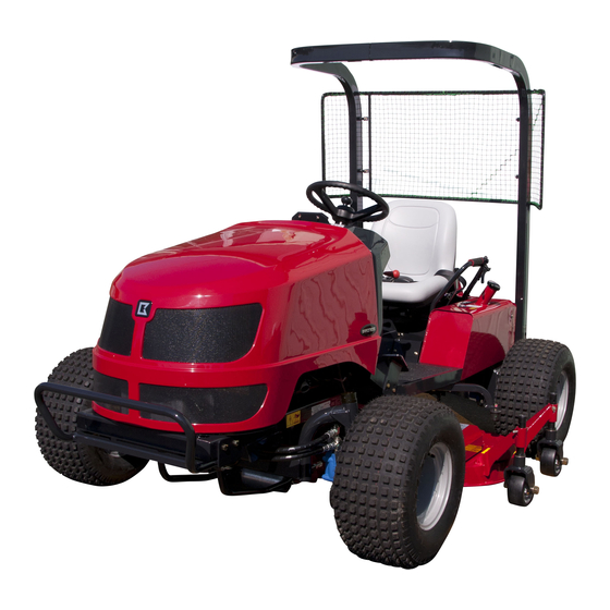
Baroness GM1700 Service Manual
3-unit mid-mount rotary mower
Hide thumbs
Also See for GM1700:
- Owner's operating manual (87 pages) ,
- Owner's operating manual (43 pages) ,
- Owner's operating manual (75 pages)
Table of Contents
Advertisement
Quick Links
Download this manual
See also:
Owner's Operation Manual
Advertisement
Chapters
Table of Contents

Related Manuals for Baroness GM1700


Summary of Contents for Baroness GM1700
- Page 1 ...
- Page 2 See the parts catalog for required parts. Caution The information described in this manual is subject to change for improvement without prior notice. Note that the Baroness product warranty may not apply to defects caused by the use of parts from other companies. Warning Symbols This manual uses the following warning symbols for handling precautions that are important for your safety.
-
Page 3: Table Of Contents
GM1700 Contents Safety............... Page 1-1 Relating to Traveling........Page 8-5 Relating to Steering........Page 8-7 Safe Operating Practices........Page 1-2 Relating to Operating Machine and Safety Signs and Instruction Signs....Page 1-5 Mower Unit............Page 8-8 Disposal............Page 2-1 Reference............Page 9-1 Waste Disposal..........Page 2-2 Specifications list.......... - Page 4 GM1700 Contents...
-
Page 5: Safety
GM1700 Safety Safe Operating Practices....... Page 1-2 Training...........Page 1-2 Preparation..........Page 1-2 Operation..........Page 1-3 Maintenance and storage....... Page 1-4 Safety Signs and Instruction Signs..Page 1-5 About Safety Signs and Instruction Signs............Page 1-5 Page 1-1... -
Page 6: Safe Operating Practices
GM1700 Safety Failure to adequately follow these safety Lack of awareness of the effect of precautions may cause an accident resulting in ground conditions, especially slopes injury or death. Incorrect hitching and load distribution Never allow children or people unfamiliar... -
Page 7: Operation
GM1700 Safety If fuel is spilled, do not attempt to start the Stay alert for humps and hollows and engine but move the machine away from other hidden hazards. the area of spillage and avoid creating any Never operate across the face of the... -
Page 8: Maintenance And Storage
GM1700 Safety Look behind and down before backing up to When machine is to be parked, stored, or left be sure of a clear path. unattended, lower the cutting units unless a positive mechanical lock is provided. Do not carry passengers. -
Page 9: Safety Signs And Instruction Signs
GM1700 Safety Disconnect battery before making any repairs. Disconnect the negative terminal first and the positive last. Reconnect positive first and negative last. Make sure that parts such as wires are not touching each other and that their covers have not come off. -
Page 10: Safety Signs And Instruction Signs
GM1700 Safety Page 1-6 Safety Signs and Instruction Signs... -
Page 11: Disposal
GM1700 Disposal Waste Disposal........Page 2-2 About the Waste disposal....... Page 2-2 Page 2-1... -
Page 12: Waste Disposal
GM1700 Disposal Waste Disposal About the Waste disposal Make sure that waste generated when servicing or repairing the machine is disposed of in accordance with local regulations. (e.g. waste oil, antifreeze batteries, rubber products, and wires etc.) Page 2-2 Waste Disposal... -
Page 13: Maintenance Standards And Maintenance
GM1700 Maintenance standards and maintenance Unit conversion........Page 3-2 Inch–millimeter conversion table.... Page 3-2 US unit–SI unit conversion table.....Page 3-3 Maintenance standards......Page 3-4 Maintenance Standards List....Page 3-4 Tightening torques......... Page 3-6 Standard tightening torques....Page 3-6 Principal tightening torques ....Page 3-9 Jacking up the machine....... -
Page 14: Unit Conversion
GM1700 Maintenance standards and maintenance Unit conversion Inch–millimeter conversion table 1 mm = 0.03937 in 1 in = 25.4 mm Fractions Decimals Fractions Decimals 1/64 0.015625 0.397 33/64 0.515625 13.097 1/32 0.03125 0.794 17/32 0.53125 13.494 3/64 0.046875 1.191 35/64 0.546875... -
Page 15: Us Unit-Si Unit Conversion Table
GM1700 Maintenance standards and maintenance US unit–SI unit conversion table To Convert Into Multiply By Miles Kilometers 1.609 Yards Meters 0.9144 Feet Meters 0.3048 Linear Measurement Feet Centimeters 30.48 Inches Meters 0.0254 Inches Centimeters 2.54 Inches Millimeters 25.4 mile Square Miles Square Kilometers 2.59... -
Page 16: Maintenance Standards
GM1700 Maintenance standards and maintenance Maintenance standards Maintenance Standards List Main body GM1700 Engine model D1105-E3B No load rpm 1,250 - 3,000 rpm API Service grade class CF or 3.0 dm (3.0 L) (0.79 gal (US)) Quantity of engine oil... - Page 17 GM1700 Maintenance standards and maintenance Mower Units Contour Deck ■ Tension spring (center deck Spring extends 35.0 mm (1.38 in) Total length of spring compresses to belt) from end of spring guide 55.0 mm (2.17 in) Tension spring (left and right Spring extends 35.0 mm (1.38 in)
-
Page 18: Tightening Torques
GM1700 Maintenance standards and maintenance Tightening torques Standard tightening torques Bolts and Nuts Important A number of bolts are used in each part of this machine. Be sure to re-tighten the bolts and nuts, because they may be loosened at the earlier stage of the use. - Page 19 GM1700 Maintenance standards and maintenance Heat-treated bolt Strength classification 8.8 Strength classification 10.9 Nominal diameter 10.9 tib3yb-002 tib3yb-003 kgf-cm lb-in kgf-cm lb-in 5 - 7 50.99 - 71.38 44.26 - 61.96 7 - 10 71.38 - 101.97 61.96 - 88.51 8 - 11 81.58 - 112.17...
- Page 20 GM1700 Maintenance standards and maintenance Hydraulic hose The tightening torques for union joints and union adaptors with parallel pipe threads (G, PF) are shown in the table below. A union joint or adaptor will not become loose or leak as long as it is tightened by the specified torque.
-
Page 21: Principal Tightening Torques
GM1700 Maintenance standards and maintenance Principal tightening torques Tightening Torque by Model GM1700_Main body Tighten the following bolts and nuts at the torque specified in the table. For thread locking adhesive, apply a middle strength thread locker (ThreeBond 1322 anaerobic adhesives). - Page 22 GM1700 Maintenance standards and maintenance Tightening Torque by Model GM1700_Contour deck Tighten the following bolts and nuts at the torque specified in the table. For thread locking adhesive, apply a middle strength thread locker (ThreeBond 1322 anaerobic adhesives). Tightening torque...
-
Page 23: Jacking Up The Machine
GM1700 Maintenance standards and maintenance Jacking up the machine Jack-up Points Front right frame About the Jacking up the machine Front left frame Center of pivot Warning Rear right frame When replacing a tire or beginning any other Rear left frame... - Page 24 GM1700 Maintenance standards and maintenance Rear right frame rwyt62-051 Jack-up Points_005 Rear left frame rwyt62-052 Jack-up Points_006 Page 3-12 Jacking up the machine...
-
Page 25: Greasing
GM1700 Maintenance standards and maintenance Greasing No. of Location Greasing About Greasing Points Pivot Since there may be adhesion or damage due Knife rotation lever fulcrum to lack of grease on moving parts, they must be greased. Brake pedal shaft fulcrum Add urea-based No. - Page 26 GM1700 Maintenance standards and maintenance Front left wheel Chain wheel mounting shaft fulcrum There is one greasing point each on the left and right. 8bq62b-131 Greasing Points_004 8bq62b-134 Knife rotation lever fulcrum Greasing Points_007 Traveling pedal shaft fulcrum Forward pedal...
- Page 27 GM1700 Maintenance standards and maintenance Brake lever shaft Tension shaft fulcrum There is one greasing point each in the left and right brake areas. 8bq62b-140 Greasing Points_013 8bq62b-137 Cam lever shaft fulcrum Greasing Points_010 Joint fulcrum There are two locations.
- Page 28 GM1700 Maintenance standards and maintenance Tension lever fulcrum Contour Deck Left/right decks Greasing Points ■ There is one point each on the left and the right deck. Grease nipples are installed in the following locations. Add grease every 50 hours of operation.
-
Page 29: Hydraulic System
GM1700 Hydraulic system Maintenance..........Page 4-2 Maintenance........... Page 4-2 Specifications......... Page 4-3 Specifications..........Page 4-3 Hydraulic System Layout......Page 4-4 Flow of Hydraulic Oil.......Page 4-6 General instructions.......Page 4-9 Hydraulic hose........Page 4-9 Hydraulic fitting........Page 4-9 Towing..........Page 4-14 Neutral..........Page 4-14 Depressurization........Page 4-14... -
Page 30: Maintenance
For those parts that must be repaired by the manufacturer, the overhaul procedure is not described in this manual. Request repairs for those parts from your dealer or Baroness. Please note that our product warranty may be void if you overhaul the device. -
Page 31: Specifications
GM1700 Hydraulic system Specifications Specifications KYB PSV2-16A 0 - 16.4 cm /rev Displacement (0 - 1.00 in /rev) 20.6 MPa High-pressure relief set Piston pump pressure (2,987.67 psi) 0.6 MPa Charge relief set pressure (87.02 psi) 9.08 cm /rev Gear pump Displacement (0.55 in... -
Page 32: Hydraulic System Layout
GM1700 Hydraulic system Hydraulic System Layout dwb7jb-010 Hydraulic System Layout_001 Wheel motor Piston pump Relief valve (DVR04) Orbitrol Gear pump (w/piston pump) Cartridge filter 2WD/4WD changeover valve Steering cylinder Filler neck breather (KVS-65K-2) Solenoid valve (HF78806-12) Up/down cylinder Page 4-4... - Page 33 GM1700 Hydraulic system Wheel motor Steering cylinder This converts the fluid energy from the pump According to the control valve that is to mechanical energy (rotation motion) in activated depending on the steering order to directly drive the machine. operation, the flow of the fluid from the This is located at each wheel.
-
Page 34: Flow Of Hydraulic Oil
GM1700 Hydraulic system Flow of Hydraulic Oil Flow of Oil during Forward Traveling ■ qat6d9-001 4WD_001 shows flow of oil. The flow of oil shows that for 4WD forward traveling. shows port name inside. Piston pump Wheel motor (rear right) - Page 35 GM1700 Hydraulic system ■ gslvj6-008 2WD_001 shows flow of oil. shows flow of supply oil of the front wheel motor. shows circulation of oil between the front wheel motor and 2WD/4WD changeover valve in the direction of the arrow. The flow of oil shows that for 2WD forward traveling.
- Page 36 GM1700 Hydraulic system Flow of Oil during Raising Mower Unit, with Power Steering Turning to Left qwbqfy-007 Flow of Oil during Raising Mower Unit, with Power Steering Turning to Left_001 shows flow of oil. The flow of oil shows that for raising the mower unit, turning the power steering to left.
-
Page 37: General Instructions
GM1700 Hydraulic system Hydraulic fitting General instructions Bite type tube fitting Hydraulic hose Preliminary tightening (Preset) Hydraulic hoses are subjected to excessive load when weathered, exposed to the sun or Cut the tube at the designated length at a chemicals, stored in a very hot storage right angle. - Page 38 GM1700 Hydraulic system Matchmark the zero point and further tightening of 3/4 to one turn will cause the sleeve to bite into the tube. w7s31b-004 Bite type tube fitting_004 Fix the temporary tightening jig onto the w7s31b-007 vise and apply hydraulic oil to the threads, tapered part, and sleeve.
- Page 39 GM1700 Hydraulic system Note: Adjustable Elbow ■ For direct tightening, use the fitting body to follow procedures 1 to 5 when using a temporary tightening jig, and set the zero point. Further tighten for 1 and 1/4 turns from the zero point.
- Page 40 GM1700 Hydraulic system Make sure that the thread portion, sheet After fitting the opposite screw, tighten the surface of the O-ring port, and O-ring are lock nut while holding the main body with not contaminated with foreign objects. a spanner etc. to ensure that the setting Apply oil or grease to the sheet surface position does not change.
- Page 41 GM1700 Hydraulic system Before connecting the joint, wind sealing Wrap it in clockwise direction (direction to ・ tape on the taper thread portion. (See "How tighten the screw). to Use the Sealing Tape" (Page 4-13) .) Wrapping in the opposite direction may cause the tape to be easily peeled off.
-
Page 42: Towing
GM1700 Hydraulic system Since this contaminant causes damage to Towing other hydraulic equipment, such debris and contaminant must be removed to prevent Important further failure of other hydraulic equipment. In the event that failure of hydraulic equipment Going over the limit of towing may lead to the is found in the hydraulic circuit, remove failure of hydraulic equipment. -
Page 43: Hydraulic Circuit Flow
GM1700 Hydraulic system Hydraulic circuit flow Traveling circuit Forward traveling (4WD) Check valve Front wheel motor 195 cm /rev Orbitrol P3 51.0 cm /rev RV4 6.9 MPa Front wheel motor 195 cm /rev Piston pump P1 16.4 cm /rev P2 9.08 cm /rev RV1 20.6 MPa... - Page 44 GM1700 Hydraulic system Backward traveling (4WD) Check valve Front wheel motor 195 cm /rev Orbitrol P3 51.0 cm /rev RV4 6.9 MPa Front wheel motor 195 cm /rev Piston pump P1 16.4 cm /rev P2 9.08 cm /rev RV1 20.6 MPa RV2 0.6 MPa...
- Page 45 GM1700 Hydraulic system Forward traveling (2WD) Check valve Front wheel motor 195 cm /rev Orbitrol P3 51.0 cm /rev RV4 6.9 MPa Front wheel motor 195 cm /rev Piston pump P1 16.4 cm /rev P2 9.08 cm /rev RV1 20.6 MPa RV2 0.6 MPa...
- Page 46 GM1700 Hydraulic system Backward traveling (2WD) Check valve Front wheel motor 195 cm /rev Orbitrol P3 51.0 cm /rev RV4 6.9 MPa Front wheel motor 195 cm /rev Piston pump P1 16.4 cm /rev P2 9.08 cm /rev RV1 20.6 MPa RV2 0.6 MPa...
-
Page 47: Steering, Raise/Lower Circuit
GM1700 Hydraulic system Steering, Raise/lower circuit Steering counter-clockwise turning, up/down cylinder raising Power steering Valve module Aperture φ1.0 RV5 relief 7.0 MPa Mower up/down cylinder Priority Orbitrol P3 displacement 51.0 cm /rev D flow divider 7 L/min RV4 relief 6.9 MPa... - Page 48 GM1700 Hydraulic system Steering clockwise turning, up/down cylinder lowering Power steering Valve module Aperture φ1.0 RV5 relief 7.0 MPa Mower up/down cylinder Priority Orbitrol P3 displacement 51.0 cm /rev D flow divider 7 L/min RV4 relief 6.9 MPa Cartridge filter...
-
Page 49: Special Tool
GM1700 Hydraulic system Special Tool List of Special Tools Pressure gauge for high pressure measurements Pressure: For the range of 0 - 35 MPa For the range of 0 - 5,076.40 psi K4701000010 For the range of 0 - 356.90 kgf/cm Primarily used for measuring the pressure of high-pressure parts. - Page 50 GM1700 Hydraulic system Pressure gauge seal Inserted between the pressure gauge K4701000050 and the pressure gauge joint. vasdfi-005 Gauge valve Used to temporarily shut off the fluid to be measured during maintenance, K4701000060 inspection, or repair etc. of the hydraulic equipments.
- Page 51 GM1700 Hydraulic system Cast iron T-joint PT3/8 PF3/8 Used to insert the pressure gauge K3024000042-Y between the hydraulic hoses. vasdfi-013 Special adapter PF1/4 PT3/8 Used as adapters for the T-joint during K3009000042-Y pressure measurements. vasdfi-015 Adapter 1013-9 Two pieces are used as adapters for...
- Page 52 GM1700 Hydraulic system WP210-9 hose 1-490 Used as a hydraulic hose for high K3105310490 pressure to extremely low pressure measurements. vasdfi-008 Screw cap (male) PF1/2 Used as a plug when the hydraulic K3008000542-Y hose is removed. q9c6v6-001 Screw cap (female) PF1/2...
- Page 53 GM1700 Hydraulic system T-joint TEFPT1/4 Used to insert the pressure gauge K3021040002-Y between the hydraulic hoses. vasdfi-013 Adapter 1013-6 Used as an adapter when installing K300006000-Y the pressure gauge to the hydraulic measurement port. q9c6v6-008 Special Tool Page 4-25...
-
Page 54: Measurement
GM1700 Hydraulic system Warm up the hydraulic oil before starting Measurement hydraulic measurement. Note Warning The most effective way of solving problems in Be sure to depressurize the hydraulic system the hydraulic system is to use a measuring before inspecting or repairing it. -
Page 55: Traveling Circuit
GM1700 Hydraulic system Traveling circuit Front Wheel Forward ■ Front wheel motor 195 cm /rev Orbitrol P3 51.0 cm /rev Pressure gauge RV4 6.9 MPa Front wheel motor 195 cm /rev Piston pump P1 16.4 cm /rev P2 9.08 cm /rev RV1 20.6 MPa... - Page 56 GM1700 Hydraulic system Remove the hydraulic hose from the Tighten the hydraulic hose so that the forward swivel joint of the left wheel motor hydraulic hose does not touch the tire of the front wheel. even if the handle is operated.
- Page 57 GM1700 Hydraulic system Reverse ■ Front wheel motor 195 cm /rev Pressure gauge Orbitrol P3 51.0 cm /rev RV4 6.9 MPa Front wheel motor 195 cm /rev Piston pump P1 16.4 cm /rev P2 9.08 cm /rev RV1 20.6 MPa RV2 0.6 MPa...
- Page 58 GM1700 Hydraulic system Remove the hydraulic hose of the reverse Tighten the hydraulic hose so that the swivel joint of the right wheel motor of the hydraulic hose does not touch the tire front wheel. even if the handle is operated.
- Page 59 GM1700 Hydraulic system Rear Wheel Forward ■ Front wheel motor 195 cm /rev Orbitrol P3 51.0 cm /rev RV4 6.9 MPa Front wheel motor 195 cm /rev Piston pump P1 16.4 cm /rev P2 9.08 cm /rev RV1 20.6 MPa RV2 0.6 MPa...
- Page 60 GM1700 Hydraulic system Remove the taper plug w/hexagon hole Tighten the hydraulic hose so that the from the hydraulic fitting. installed hydraulic hose does not touch the moving parts. g5t8is-021 g5t8is-023 Forward_002 Forward_004 Hydraulic fitting Pressure gauge for high pressure...
- Page 61 GM1700 Hydraulic system Reverse ■ Front wheel motor 195 cm /rev Orbitrol P3 51.0 cm /rev RV4 6.9 MPa Front wheel motor 195 cm /rev Piston pump P1 16.4 cm /rev P2 9.08 cm /rev RV1 20.6 MPa RV2 0.6 MPa...
- Page 62 GM1700 Hydraulic system Remove the taper plug w/hexagon hole Tighten the hydraulic hose so that the from the hydraulic fitting. installed hydraulic hose does not touch the moving parts. 7edlvx-024 Reverse_002 7edlvx-026 Reverse_004 Hydraulic fitting Pressure gauge for high pressure...
-
Page 63: Up/Down Circuit
GM1700 Hydraulic system Up/Down circuit Power steering Valve module Aperture φ1.0 RV5 relief 7.0 MPa Mower up/down cylinder Priority Pressure gauge Orbitrol P3 displacement 51.0 cm /rev D flow divider 7 L/min RV4 relief 6.9 MPa Cartridge filter 10 um... - Page 64 GM1700 Hydraulic system Lower the mower units. Tighten the hydraulic hose so that the installed hydraulic hose does not touch the Remove the hydraulic hose installed to the moving parts. 90° elbow of the up/down port of the valve module.
-
Page 65: Steering Circuit
GM1700 Hydraulic system Steering Circuit Pressure gauge Power steering Valve module Aperture φ1.0 RV5 relief 7.0 MPa Mower up/down cylinder Priority Orbitrol P3 displacement 51.0 cm /rev D flow divider 7 L/min RV4 relief 6.9 MPa Cartridge filter 10 um... - Page 66 GM1700 Hydraulic system Remove the hydraulic hose from the 90° Tighten the hydraulic hose so that the elbow attached to the hydraulic cylinder. hydraulic hose does not touch the tire even if the handle is operated. 9idjnn-023 Steering Circuit_002 9idjnn-025...
-
Page 67: Charge Circuit
GM1700 Hydraulic system Charge Circuit Pressure gauge Front wheel motor 195 cm /rev Orbitrol P3 51.0 cm /rev RV4 6.9 MPa Front wheel motor 195 cm /rev Piston pump P1 16.4 cm /rev P2 9.08 cm /rev RV1 20.6 MPa RV2 0.6 MPa... - Page 68 GM1700 Hydraulic system Remove the hydraulic hose from the 90° Tighten the hydraulic hoses. elbow attached to the hydraulic fitting-front. zg85f8-030 zg85f8-028 Charge Circuit_004 Charge Circuit_002 Hydraulic hose Hydraulic fitting-front Charge hydraulic hose 90° elbow Pressure gauge for extremely low...
-
Page 69: General Inspection And Repair
See the list in "Tightening torques" (Page to clean the circuit. 3-6) . Note that the Baroness product warranty may In the event of contamination or failure of the not apply to defects caused by incorrect or hydraulic circuit, clean and/or replace the parts. -
Page 70: Air Bleeding
GM1700 Hydraulic system Apply the parking brake, and then lower the Air bleeding operating machine. Stop the engine, and then remove the key. Caution Warning When you replace or repair the motor, pump, cylinder, etc, make sure that the hydraulic Be sure to depressurize the hydraulic system system is properly connected. -
Page 71: Inspection And Repair Of Each Section
GM1700 Hydraulic system Start the engine and depress the traveling Check that the traveling is in neutral pedal while it is running at low rpm. position. The charge pump sucks oil, air in the When any adjustment is needed, raise all... - Page 72 GM1700 Hydraulic system Hydraulic Oil Supply Change of Hydraulic Oil Important Warning Do not mix different types of oil. When you change the hydraulic oil, be sure to drain it into a bowl and discard it in accordance with local laws and regulations.
-
Page 73: Hydraulic Oil Filter
GM1700 Hydraulic system Open the tank cap, and then pour new oil Hydraulic oil filter from the fill port until the oil level reaches the middle of the oil gauge on the hydraulic Replacement of Hydraulic Oil Filter tank. The hydraulic tank capacity is Important approximately 22.0 dm... - Page 74 GM1700 Hydraulic system Page 4-46 Inspection and repair of each section...
-
Page 75: Electrical System
GM1700 Electrical system Maintenance..........Page 5-2 About Maintenance.........Page 5-2 Specifications......... Page 5-2 Adjusted Value........Page 5-2 Electrical Part Layout......Page 5-3 Special Tool..........Page 5-5 Special tools list........Page 5-5 Measurement...........Page 5-5 Battery............ Page 5-5 Interlock system........Page 5-6 Adjustment..........Page 5-7 Neutral switch......... Page 5-7 Knife rotation lever switch.......Page 5-8... -
Page 76: Maintenance
GM1700 electrical system. For daily inspections and maintenance as well as machine handling, refer to the GM1700 Operator's Manual and Parts Catalog. Also, for details for handling of the battery, please refer to the separate Battery Instruction Manual. -
Page 77: Electrical Part Layout
GM1700 Electrical system Electrical Part Layout erq4ky-010 Electrical Part Layout_001 Battery Neutral switch Automatic return switch Glow lamp timer Fuse Box Pilot lamp Safety Switches Relay comp. (starter) Water temperature gauge Fusible link 30 A Buzzer EBM-12 type Power relay 411... - Page 78 GM1700 Electrical system Battery Relay comp. (starter) The battery supplies power to the starter at The relay comp. is one of the relays that the start of the engine, as well as to all constitute the interlock system. electrical parts.
-
Page 79: Special Tool
GM1700 Electrical system Each relay controls the start and driving of Specific weight converted for 20 ° C the engine in combination with the status Measured specific weight signal of each safety switch. Fluid temperature at measurement It is located under the hood. -
Page 80: Measurement
GM1700 Electrical system Interlock system Battery charging Follow this procedure to fully charge the The interlock system is a safety system to battery. prevent injury or accident caused by lack of attention of operator, using combined control Warning with multiple switches and sensors. -
Page 81: Adjustment
GM1700 Electrical system Interlock System Operation Requirements Knife rotation Seat Parking brake Traveling pedal lever OFF (Take the foot To start the engine, ON (Sitting) ON (Applied) off) ON (Forward or To travel, ON (Sitting) OFF (Released) reverse) To operate (rotary knife rotation) -
Page 82: Knife Rotation Lever Switch
GM1700 Electrical system Depress the traveling pedal to confirm that Important the engine is not started. If the switch contact point is pressed more Make sure that the engine is started when than a stroke of the switch, the switch may be the traveling pedal is neutral. -
Page 83: Parking Brake Switch
GM1700 Electrical system Parking brake switch Important After adjusting the foot brake wire, check that The parking brake is equipped with a parking the machine is firmly stopped with the parking brake switch, one part of the interlock system. brake at notch 3 - 4. -
Page 84: Electrical Components
GM1700 Electrical system Electrical components Important If the switch contact point is pressed more About the Electrical components than a stroke of the switch, the switch may be damaged. Warning When servicing electrical components, be Make adjustments by pulling back the sure to disconnect the negative battery cable. -
Page 85: Seat Switch
GM1700 Electrical system Automatic return switch Solenoid valve Fuse Box Key switch Seat Switch The seat switch is located right underneath the seat and is not usually conducted. It is normal if it is conducted when seated (pressed). 6m8tje-001 Seat Switch_001... -
Page 86: Knife Rotation Lever Switch
GM1700 Electrical system Knife Rotation Lever Switch Connector terminal 1 Connector terminal 2 The knife rotation lever switch is located in Connector terminal 3 the knife rotation lever fulcrum (under the Connector terminal 4 hood) and has two systems of circuits. -
Page 87: Parking Brake Switch
GM1700 Electrical system Parking brake switch Connector terminal 1 Connector terminal 2 The parking brake switch is located in the Connector terminal 3 brake pedal fulcrum (under the hood) and Connector terminal 4 has two systems of circuits. 67xzzh-016 Parking Brake Switch_001... -
Page 88: Mower Unit Up/Down Switch
GM1700 Electrical system Mower Unit Up/Down Switch Inspection of Auto Return Switch Prepare a stand alone switch. Caution It is normal if the switch terminal 1 and 2 Before raising or lowering the mower units, are conducted between them when the... -
Page 89: Power Relay
GM1700 Electrical system Solenoid valve Power relay [MR5A411A1K (brown)] Inspection of Solenoid Fuel Control Relay ■ Remove the connector of the solenoid. The fuel control relay (power relay [MR5A411A1K] brown) controls the operation It is normal if resistance between of the engine stop solenoid (= supply or stop connectors of the solenoid is about 7.2 Ω. -
Page 90: Key Switch
GM1700 Electrical system It is normal if there is no conduction Key Position and Device Operation between both of relay terminal 3 and 5, 6 and 7. ON (Run) ■ The diesel engine on the machine runs or stops based on the fuel supply. -
Page 91: Pilot Lamps
GM1700 Electrical system Glow (thermo-start) START ■ ■ When the ignition key is kept in the "GLOW" The engine starts by rotating the starter position, the glow plug is generating heat motor, when the magnet switch of the starter and the thermo-start lamp is turned on. - Page 92 GM1700 Electrical system Charge Thermo-start When the ignition key is set to the "ON" When the ignition key is set to the "GLOW" position before the engine starts, the position, it illuminates as the glow plug alternator IG-terminal (yellow) is energized generates heat.
-
Page 93: Water Temperature Gauge
GM1700 Electrical system Water Temperature Gauge Starter relay Glow Lamp Timer The water temperature gauge is connected to a water temperature sensor located on the The glow lamp timer is located in the hood and engine cylinder head (in the left front of the controls illumination of the thermo-start lamp. -
Page 94: Fusible Link
GM1700 Electrical system The machine uses a mini fuse for automobiles. Fusible Link Replace an old fuse with a new fuse of the specified capacity. Fuse capacity of the fusible link is described below. Engine stop solenoid: 30 A ・... -
Page 95: Fuel Pump
GM1700 Electrical system Replacement of Fuse Solenoid Specifications Rated Important DC 12 V Voltage To remove the fuse, use the tools in the tool Rated 1.5 A box. Current Discharge 400 cc/min Quantity sen9yf-001 Replacement of Fuse_001 Fuel Pump The fuel pump is located at front right side in... -
Page 96: Buzzers
GM1700 Electrical system Buzzers Delay timer Water Temperature Buzzer (Seat safety switch timer) The delay timer is located under the hood and, The water temperature buzzer is a warning if the driver is away from the seat for 0.9 buzzer connected to the thermo switch on the second or longer while driving this machine, it engine side. - Page 97 GM1700 Electrical system When the switch is turned "ON," the lamp Delay timer turns on. Coupler If the lamp turns off 0.9 second after the Coupler position diagram switch is turned "OFF," the delay timer is Wiring diagram normal. Inspection of Delay Timer Remove the delay timer from the machine.
-
Page 98: General Inspection And Repair
GM1700 Electrical system General inspection and repair Danger Danger Do not allow anyone to handle the battery who Battery does not fully understand the correct battery Handling of the battery handling procedures and relevant dangers. When handling the battery, wear protective For details on handling the battery, please glasses and rubber gloves, etc. - Page 99 GM1700 Electrical system Danger Danger Caution Do not allow anyone to handle the battery who If the electrolyte overflows from the battery, does not fully understand the correct battery wipe it with a wet cloth. handling procedures and relevant dangers.
- Page 100 GM1700 Electrical system Inspection of the mounting bracket When adding distilled water, loosen and Ensure that the battery is firmly secured by remove the vent plug and add distilled the mounting bracket. water up to the “UPPER” (maximum level If it is not, tighten the nuts securing the line) limit.
- Page 101 GM1700 Electrical system Disconnect the positive cable. Warning Loose the mounting bracket and remove When connecting the machine-side cable the old battery. terminals to the battery, ensure that they are correctly connected to the positive and negative terminals. Secure the battery firmly with the mounting bracket.
- Page 102 GM1700 Electrical system Firmly secure the negative cable to the Warning negative terminal. Charging the battery mounted on the vehicle may cause ignition, explosion, or damage on the vehicle or equipment. If there is no way other than to charge the...
- Page 103 GM1700 Electrical system Important Fast charging is not suitable for charging to recover the battery left for a long time. A high electrolyte temperature deteriorates parts such as polar plates inside the battery and shorten its lifetime. General inspection and repair...
- Page 104 GM1700 Electrical system Page 5-30 General inspection and repair...
-
Page 105: Main Body
GM1700 Main body Maintenance..........Page 6-2 About Maintenance.........Page 6-2 Specifications......... Page 6-2 Tire Pneumatic Pressure......Page 6-2 Adjusted Value........Page 6-2 Special Tool..........Page 6-3 Special tools list........Page 6-3 Adjustment..........Page 6-4 Brake............Page 6-4 Traveling rod...........Page 6-6 Throttle wire..........Page 6-9 Toe Angle.......... -
Page 106: Maintenance
About Maintenance This chapter provides descriptions of the main inspection and maintenance procedures for the GM1700. For daily inspections and maintenance as well as machine handling, refer to the GM1700 Operator's Manual and Parts Catalog. Specifications Tire Pneumatic Pressure psi=lb-in... -
Page 107: Special Tool
GM1700 Main body Reverse rod Adjusted Value of the Foot Brake Wire The clearance adjusted value of brake wire on the pedal side is described below. 166.0mm(6.54in) 1 mm (0.039 in) 1 mm (0.039 in) jc5o3p-011 Adjustment Value of Traveling Rod_003... -
Page 108: Adjustment
GM1700 Main body Adjustment Danger Danger It would be extremely dangerous and may Brake result in an unexpected accident if the left and Adjustment of Brake right brakes are not equally effective. If the left and right brakes are not equally... - Page 109 GM1700 Main body Follow the steps below to adjust the parking Adjustment of Knife Brake brake. Remove the rear cover. Check position of the notch of the parking brake. Make sure that the knife rotation lever is set to the "OFF" position.
-
Page 110: Traveling Rod
GM1700 Main body Follow the same steps to adjust the forward Traveling rod pedal. The height of the position of the forward Adjustment of Traveling Rod pedal should be the same as that of the The return of the pedal neutral rod reverse pedal. - Page 111 GM1700 Main body Make sure that the length of the forward Make sure that the length of the neutral rod is 489.0 mm (19.25 in). adjustment rod is 186.0 mm (7.32 in). Loosen the lock nut as necessary to Loosen the lock nut as necessary to make adjustment.
- Page 112 GM1700 Main body Adjusting the Neutral Position of the Piston ■ Cam lever Pump Cam lever shaft Shaft seat Caution Lock nut A Threaded rod Make sure not to touch rotating tires. Lock nut B If the machine moves forward or backward...
-
Page 113: Throttle Wire
GM1700 Main body Shift the throttle lever to the maximum rpm, Throttle wire adjust the engine rpm to 2,800 rpm by the adjustment bolt, and secure it with the lock Adjustment of Throttle Wire nut. Movement of the lever may become dull due... -
Page 114: Inspection And Repair Of Each Section
GM1700 Main body Straighten the front wheels and then Inspection and repair of each section measure the front width A and the rear width B between the front wheels. Brake Loosen the left and right lock nuts, and then A worn brake shoe will increase the amount of rotate the tie rod to make adjustment. - Page 115 GM1700 Main body Apply grease to the sliding parts when Spring assembling. Turn the spring holder 90 degrees while Use the grease for the brake and be sure not to apply the friction surface of the shoe. pressing it and remove it.
- Page 116 GM1700 Main body Page 6-12 Inspection and repair of each section...
-
Page 117: Operating Machine And Mower Units
GM1700 Operating Machine and Mower Units Contour Deck.......... Page 7-2 Maintenance........... Page 7-2 Inspection and repair of each section... Page 7-23 Page 7-1... -
Page 118: Contour Deck
Operating Machine and Mower Units Contour Deck Maintenance Maintenance This chapter describes primary checking and maintenance operations for the GM1700 mower unit. For information on daily checks, maintenance and handling of the machine, please refer to the separate GM1700 Owner's Operating Manual and Parts Catalogue. - Page 119 GM1700 Operating Machine and Mower Units Adjusted Value ■ Spring extends 35.0 mm Total length of spring Tension spring (center (1.38 in) from end of spring compresses to 55.0 mm deck belt) guide (2.17 in) Spring compression distance Spring extends 35.0 mm...
- Page 120 GM1700 Operating Machine and Mower Units 6203 Bearing driver Used to knock-in and install the K4802000882 bearings with outer Φ40 and inner Φ17. q9c6v6-009 Page 7-4 Contour Deck...
- Page 121 GM1700 Operating Machine and Mower Units GM1700-2161Z0 Adjustment Contour deck cutting height adjustment label Adjustment of Cutting Height ■ Cutting Height Table Important Adjust all mower units to the same cutting height. The adjustment range for the cutting height is 35 - 95 mm (15 mm spacing, 5 levels).
- Page 122 GM1700 Operating Machine and Mower Units Cutting height gauge wheel Cutting height gauge wheel Bolt Washer Cotter pin Remove the cotter pin and washer from the cutting height gauge wheel at the Refer to the Cutting Height Table, and front of the deck, and then remove the then change the hole positions.
- Page 123 GM1700 Operating Machine and Mower Units Refer to the Cutting Height Table, and Belt then change the hole positions. Tension spring Insert the pin, and then securely install the caster with the washer and cotter pin. Lock nut Adjustment of Belt Tension ■...
- Page 124 GM1700 Operating Machine and Mower Units Swing Stoppers Lift Stoppers The swing stoppers fulfill the role of The lift stoppers fulfill the role of preventing suppressing swing when the mower unit is interference between the mower unit and raised while keeping the deck horizontal by the frame.
- Page 125 GM1700 Operating Machine and Mower Units Remove the clip pin and then remove the Removal and installation of each section deck tow plate from the main body. Follow the same steps to remove them Mower unit ■ from the other side.
- Page 126 GM1700 Operating Machine and Mower Units Raise the bumper with a hoist, etc., to lift Start the engine, and then raise the up the front wheels of the machine, and mower units. pull out the mower unit in the direction of the arrow to remove it.
- Page 127 GM1700 Operating Machine and Mower Units Remove the rotary knife. Important The tightening torque for the knife mounting bolt is 130 - 150 N-m (1,325.61 - 1,529.55 kgf- cm). Install the rotary knife. For installing the rotary knife, reverse the removing procedure.
- Page 128 GM1700 Operating Machine and Mower Units Pull out the universal joint. Installation of Universal Joint Danger Danger The rotary knife is an edged tool. Handle it carefully, since it could cut your hands or legs. Warning Use the jack-up points identified in this manual when jacking up the machine.
- Page 129 See the " "Tightening torques" (Page 3-6) " Loosen the nut of the tension rod to list. the extent of the thread. Note that the Baroness product warranty may not apply to defects caused by incorrect or overtorque tightening, etc. For installation, reverse the removing procedure.
- Page 130 Installation of Left and Right Deck Housing washer and pulley. Caution See the " "Tightening torques" (Page 3-6) " list. Note that the Baroness product warranty may not apply to defects caused by incorrect or overtorque tightening, etc. For installation, reverse the removing procedure.
- Page 131 GM1700 Operating Machine and Mower Units Remove the knife mounting bolt. Gearbox Assy Center knife shaft Knife mounting bracket Key with one round end Remove the bolt from the housing. Remove the housing and cover from the mower unit. gjqnn2-001...
- Page 132 Assy in the direction of the arrow. Caution See the " "Tightening torques" (Page 3-6) " list. Note that the Baroness product warranty may not apply to defects caused by incorrect or overtorque tightening, etc. For installation, reverse the removing procedure.
- Page 133 Apply the parking brake, and then raise list. the mower unit so that the cutting height Note that the Baroness product warranty may wheels do not touch the ground. not apply to defects caused by incorrect or Stop the engine, and then remove the overtorque tightening, etc.
- Page 134 Stop the engine, and then remove the key. Caution See the " "Tightening torques" (Page 3-6) " list. Note that the Baroness product warranty may not apply to defects caused by incorrect or overtorque tightening, etc. g2nuyq-002 For installation, reverse the removing Removal of Center Deck Rear Wheel Assy_002 procedure.
- Page 135 Handle it carefully, since it could cut your hands or legs. Caution See the " "Tightening torques" (Page 3-6) " list. Note that the Baroness product warranty may not apply to defects caused by incorrect or overtorque tightening, etc. For installation, reverse the removing procedure.
- Page 136 GM1700 Operating Machine and Mower Units Follow the steps below to remove the left Contour Deck ■ and right decks. Removal of Left and Right Decks Danger Danger The rotary knife is an edged tool. Handle it carefully, since it could cut your hands or legs.
- Page 137 Handle it carefully, since it could cut your hands or legs. Caution See the " "Tightening torques" (Page 3-6) " list. Note that the Baroness product warranty may xazugu-004 not apply to defects caused by incorrect or Removal of Left and Right Decks_004 overtorque tightening, etc.
- Page 138 GM1700 Operating Machine and Mower Units Remove the U nut and then remove Remove the cotter pin and pull out the the screw rod Assy. tension lever Assy in the direction of the arrow. 8f7vg6-002 8f7vg6-004 Removal of the tension lever_002...
- Page 139 Caution See the " "Tightening torques" (Page 3-6) " list. Note that the Baroness product warranty may not apply to defects caused by incorrect or overtorque tightening, etc. For installation, reverse the removing procedure.
- Page 140 GM1700 Operating Machine and Mower Units Change of Rotary Knife ■ Total width Blade edge Danger Danger Blade base Sail The rotary knife is an edged tool. less than 2/3 Take extra care in handling since they could cut your hands or legs.
- Page 141 GM1700 Operating Machine and Mower Units Grinding of Rotary Knife ■ Total width Blade edge Danger Danger Blade base Sail The rotary knife is an edged tool. 2/3 or more Take extra care in handling since they could cut your hands or legs.
- Page 142 GM1700 Operating Machine and Mower Units Follow the steps below to grind the rotary Balancing of Rotary Knife ■ knife. Remove the rotary knife from the machine. Danger Danger (See "Contour Deck" (Page 7-10) "Change The rotary knife is an edged tool.
- Page 143 GM1700 Operating Machine and Mower Units Remove the air breather. Gearbox Inspection of Gearbox ■ Wear of bearing due to frequent use and/or damage of bearing etc. caused by invasion of water may prevent smooth rotation of the vertical and horizontal shafts. Inspect and replace the parts such as the oil seal or bearing.
- Page 144 GM1700 Operating Machine and Mower Units Remove the four bolts. Gear case Assy Vertical shaft Copper solid rod Remove the 19-tooth bevel gear. Remove the 24-tooth bevel gear in the direction of the arrow. 5s6or7-004 Inspection of Gearbox_003 Bolt Spring washer...
- Page 145 GM1700 Operating Machine and Mower Units Remove the taper plug w/hexagon hole. Remove the horizontal shaft w/bearing from the gear case by using a copper solid rod, with paying attentions not to scratch the spline part. 5s6or7-009 Inspection of Gearbox_008...
- Page 146 GM1700 Operating Machine and Mower Units Remove the vertical shaft from the Important gearbox lid Assy in the direction of the arrow. When assembling, remove the old packing and wipe out all of the old liquid gasket and then attach a new packing.
- Page 147 GM1700 Operating Machine and Mower Units Install the gearbox lid Assy onto the Driver vertical shaft by using a driver and secure it with the stop ring. Apply 20 g (0.71 oz) of grease to the upper part of the bearing of the horizontal shaft.
- Page 148 GM1700 Operating Machine and Mower Units Apply the liquid gasket to the oil seal and Apply the liquid gasket to the packing. install it in the direction of the arrow by using a driver. 5s6or7-023 Inspection of Gearbox_024 5s6or7-021 Gear case...
- Page 149 Operating Machine and Mower Units Apply the liquid gasket. Caution "Tightening torques" (Page 3-6) See the list. Note that the Baroness product warranty may not apply to defects caused by incorrect or overtorque tightening, etc. Install four bolts and spring washers.
- Page 150 GM1700 Operating Machine and Mower Units Inject grease from the oil filling port and Remove the rotary knife. (See "Change of install the oil filling plug. Rotary Knife" (Page 7-24) "Contour Deck" [Grease amount 240 g (8.47 oz)] (Page 7-10) .) Remove the belt.
- Page 151 GM1700 Operating Machine and Mower Units Use an iron pipe, etc. and tap it with a Apply a profuse amount of grease to the plastic hammer to remove the bearing. lip of the oil seal. 5ymvks-003 5ymvks-006 Inspection of Center Deck Housing_003...
- Page 152 GM1700 Operating Machine and Mower Units In order to avoid damage to the shaft Use an iron pipe etc., and tap it with a when removing it, use an iron pipe, etc., plastic hammer to remove the bearing. and tap the pipe with a plastic hammer.
- Page 153 GM1700 Operating Machine and Mower Units For installation, reverse the removing Knock one end of the wheel shaft with a procedure. plastic hammer to push out the shaft. Note: Use a driver to drive in the oil seal and bearing.
- Page 154 Caution See the list in "Tightening torques" (Page Caution 3-6) . Note that the Baroness product warranty may Wear gloves when touching edged tools to not apply to defects caused by incorrect or avoid cutting your hands. overtorque tightening, etc.
- Page 155 GM1700 Operating Machine and Mower Units Remove the bracket by tapping the bolt Important with a wooden hammer while holding the bracket by one hand. Be sure to replace the bearing with new one. Follow the steps below to install the wheel into the bracket.
- Page 156 GM1700 Operating Machine and Mower Units Drive the wheel evenly into the bearing Bearing attached to the shaft. Driver Insert the washer and wheel tightening washer into the shaft of the bracket and tighten them with the bolts and spring washers.
- Page 157 GM1700 Operating Machine and Mower Units Danger Danger Vise Bracket The rotary knife is an edged tool. Wheel Handle it carefully, since it could cut your hands or legs. Follow the steps below to remove the bearing from the wheel.
- Page 158 GM1700 Operating Machine and Mower Units Follow the steps below to install the wheel Rubber wheel into the bracket. Insert the collar into the shaft of the Insert the washer into the shaft of the bracket. bracket. 5is35y-007 5is35y-004 Inspection of Rear Wheel of Center Deck_007...
- Page 159 GM1700 Operating Machine and Mower Units Follow the same steps to complete the Caution installation on the opposite side by the same procedure. Wear gloves when touching edged tools to avoid cutting your hands. Secure the caster wheel Assy with a vise.
- Page 160 GM1700 Operating Machine and Mower Units Remove the bearing hitting it from front Pull out the shaft from the front wheel arm to back and from side to side alternately in the direction of the arrow and remove with a wooden hammer using an iron the iron washer.
- Page 161 GM1700 Operating Machine and Mower Units Insert the copper washer and iron washer into the shaft caring for the order. Insert the shaft set into the front wheel arm. y5nvao-006 Inspection of Caster Wheel_007 Vise Front wheel arm Iron pipe...
- Page 162 GM1700 Operating Machine and Mower Units Follow the steps below to install the Front wheel arm bearing onto the wheel. Front wheel shaft Drive the bearing into the wheel evenly. Copper washer (It enters deeper inside beyond the Collar upper face of the housing.)
- Page 163 Handle it carefully, since it could cut your hands or legs. Caution See the " "Tightening torques" (Page 3-6) " list. Note that the Baroness product warranty may not apply to defects caused by incorrect tightening etc. 5yhx8g-003 Inspection of Relay Pulley Stage Comp_003...
- Page 164 GM1700 Operating Machine and Mower Units Place the relay pulley on the vise with the Important side where the stop ring was installed facing downward to secure space for the Be sure to replace the bearing with new one. bearing to come out.
- Page 165 Make sure that the pulley rotates smoothly. Caution See the " "Tightening torques" (Page 3-6) " list. Note that the Baroness product warranty may not apply to defects caused by incorrect tightening etc. Follow the steps below to remove the tension pulley.
- Page 166 GM1700 Operating Machine and Mower Units Remove the stop ring from the tension Remove the stop ring on the other side pulley shaft. as well. ud8e63-002 ud8e63-004 Inspection of Center Deck Tension Lever Assy_002 Inspection of Center Deck Tension Lever Assy__004...
- Page 167 GM1700 Operating Machine and Mower Units Follow the steps below to install the Drive the tension pulley into the tension tension pulley onto the lever. lever with the cap mounting side up. Install the stop ring onto one side of the tension pulley.
- Page 168 Make sure that there is no wear or crack ・ list. of the tension pulley. Note that the Baroness product warranty may Make sure that there is no abrasion or rust ・ not apply to defects caused by incorrect of the bearing and no play between the tightening etc.
- Page 169 GM1700 Operating Machine and Mower Units Remove the stop ring from the tension Remove the stop ring on the other side pulley shaft. as well. 4uyhhy-002 4uyhhy-004 Inspection of Left and Right Deck Tension Lever Inspection of Left and Right Deck Tension Lever...
- Page 170 GM1700 Operating Machine and Mower Units Follow the steps below to install the Drive the tension pulley into the tension tension pulley onto the lever. lever with the cap mounting side up. Install the stop ring onto one side of the tension pulley.
-
Page 171: Troubleshooting
GM1700 Troubleshooting Relating to the Engine......Page 8-2 Relating to Traveling......Page 8-5 Relating to Steering........Page 8-7 Relating to Operating Machine and Mower Unit..........Page 8-8 Page 8-1... -
Page 172: Relating To The Engine
GM1700 Troubleshooting Relating to the Engine Problem Cause Reference The interlock system was activated (not sitting on Electrical System - the seat, parking brake not applied, the knife Measurements - Interlock rotation lever switch not set to the "OFF" position,... - Page 173 GM1700 Troubleshooting Problem Cause Reference Electrical System - Electrical Components - Insufficient battery capacity or loose terminals General Inspections/ Repairs - Battery Electrical System - Electrical Components - Faulty ignition key switch Power Relays - Ignition Key Switch Engine Maintenance...
- Page 174 GM1700 Troubleshooting Problem Cause Reference General Inspections/ Insufficient battery electrolyte Repairs - Battery Electrical System - Measurement - Battery Electrical System - Faulty battery Electrical Components - General Inspections/ No charge Repairs - Battery This machine's Owner's Insufficient fan belt tension...
-
Page 175: Relating To Traveling
GM1700 Troubleshooting Relating to Traveling Problem Cause Reference This machine's Owner's Engine rpm is slow. Operating Manual Engine Maintenance Engine does not run smoothly Manual This machine's Owner's The parking brake is applied. Operating Manual Main body - Adjustment -... - Page 176 GM1700 Troubleshooting Problem Cause Reference Adjusting the Neutral Malfunction of neutral of the piston pump Position of the Piston Pump It travels forward or backward Malfunction of bearing of neutral lever part Replacement of the bearing even when the pedal is released.
-
Page 177: Relating To Steering
GM1700 Troubleshooting Relating to Steering Problem Cause Reference This machine's Owner's Engine rpm is slow Operating Manual This machine's Owner's Tire pressure is low Operating Manual Maintenance standards Lack of grease on the kingpin and maintenance - Greasing This machine's Owner's... -
Page 178: Relating To Operating Machine And Mower Unit
GM1700 Troubleshooting Relating to Operating Machine and Mower Unit Problem Cause Reference Electrical System - Faulty 15 A fuse Electrical Components - Fuse - Fuse Box (E) Electrical system - Malfunction of Auto Return Switch Electrical components - Mower unit up/down switch... -
Page 179: Reference
GM1700 Troubleshooting Problem Cause Reference Operating machine and Malfunction of bearing and shaft of mower unit mower unit - Inspection of housing each part, repair - Housing Operating machine and mower unit - Removal and Malfunction of the mower unit pulley key... - Page 180 GM1700 Troubleshooting Problem Cause Reference Maintenance standards Adhesion, deformation, and wear of the mower Mowed face is not flat and maintenance - unit installation part Greasing This machine's Owner's Engine rpm is slow Operating Manual Mower unit operating Operation speed is fast...
- Page 181 GM1700 Reference Specifications list........Page 9-2 Main body..........Page 9-2 Mower unit..........Page 9-3 Maintenance Schedule......Page 9-4 Hydraulic circuit diagram.......Page 9-7 Electrical Circuit........Page 9-8 Electric wiring diagram......Page 9-9 Consumable parts list......Page 9-10 Main body..........Page 9-10 Mower unit..........
-
Page 182: Specifications List
GM1700 Reference Specifications list Main body Total length 255.0 cm (100.39 in) Total width 159.0 cm (62.60 in) Roof 197.0 cm (77.56 in) Total height Handle 121.0 cm (47.64 in) Wheelbase 147.0 cm (57.87 in) Tread 132.0 cm (51.97 in) Total weight 743.0 kg (1,638.01 lb) -
Page 183: Specifications List
GM1700 Reference Mower unit Contour Deck Total length 108.0 cm (42.52 in) Dimensions Total width 183.0 cm (72.05 in) Total height 37.0 cm (14.57 in) Weight 166.0 kg (365.96 lb) Operating width (Cutting width) 151.0 cm (59.45 in) Operating height (Cutting height) 3.5 - 9.5 cm (1.38 - 3.74 in) -
Page 184: Maintenance Schedule
GM1700 Reference Maintenance Schedule GM1700 Follow the maintenance schedule below. ○・・・Inspect, adjust, supply, clean ●・・・Replace (first time) △・・・Replace Maintenance item Tightening the parts ○ Fuel ○ Air cleaner 8 hrs. Engine oil ○ ● △ (first time) 50 hrs. Engine oil filter ○... - Page 185 GM1700 Reference Maintenance item Hydraulic motor oil Power unit oil Transmission oil ○ ● △ Hydraulic hose (moving part) ○ △ Hydraulic hose (fixed part) ○ △ "Replacem Air cleaner ○ △ △ ent of Air Cleaner". Electromagnetic pump filter Fuel strainer ○...
- Page 186 GM1700 Reference Maintenance item Tightening the parts ○ Greasing, oiling ○ V-belt ○ △ Cover ○ Oil leakage ○ Hydraulic hose (moving part) ○ △ Hydraulic hose (fixed part) ○ △ ○ Duct ○ Cleaning the exterior ○ The values for consumables are not guaranteed.
-
Page 187: Hydraulic Circuit Diagram
GM1700 Reference Hydraulic circuit diagram Orbitrol UAS070A08B2D (EATON) Displacement 51 cc/rev Relief 6.9 MPa Front wheel Flow divider 7L/min 2-200-BS4S (EATON) Steering 195 cc/rev 25.4 L/min PSV2-16A (KYB) Priority 7 L/min Main 16 cc/rev x 2 Relief 20.6 MPa Charge 9.08 cc/rev Relief 0.6 MPa... -
Page 188: Electrical Circuit
GM1700 Reference Electrical Circuit Glow Water temperature sensor Fuel SOL vgmkvc-019 Electrical Circuit_001 Page 9-8 Electrical Circuit... -
Page 189: Electric Wiring Diagram
GM1700 Reference Electric wiring diagram kcl9bj-026 Electric wiring diagram_001 Electric wiring diagram Page 9-9... -
Page 190: Consumable Parts List
GM1700 Reference Consumable parts list Main body Remark Code Part name Qty. Fan belt PF1G345-9701-0 V-belt (FM36) Oil element PF16271-3209-3 Oil element Air cleaner element PFT0270-1632-0 Air cleaner element Fuel filter PF1G313-4301-1 Fuel filter Assy Hydraulic cartridge filter K3412000050 Replacement filter C-SP04-10... - Page 191 GM1700 Reference Remark Code Part name Qty. Key switch PF15248-6359-2 Starter switch Assy Brake wire, left K1120182500 Brake wire 1825 Brake wire, right K1120199500 Brake wire 1995 Throttle wire K1110063000 Throttle wire 630 Tension wire K1140231500 Tension wire 2315 Brake shoe for knife...
- Page 192 Page 9-12 Consumable parts list...
Need help?
Do you have a question about the GM1700 and is the answer not in the manual?
Questions and answers