Table of Contents
Advertisement
Quick Links
Advertisement
Chapters
Table of Contents

Subscribe to Our Youtube Channel
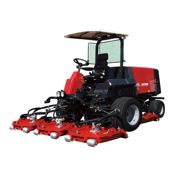
Related Manuals for Baroness GM2810


Summary of Contents for Baroness GM2810
- Page 1 5-Unit Rotary Mower Service Manual Serial No. 10001- Ver.1.0...
- Page 2 The information described in this manual is subject to change for improvement without prior notice. When replacing parts, be sure to use genuine Baroness parts or parts designated by Kyoeisha. Note that the Baroness product warranty may not apply to defects caused by the use of parts from other companies.
-
Page 3: Table Of Contents
GM2810 Contents Safety .............. Page 1-1 Troubleshooting ..........Page 8-1 Safe Operating Practices .......Page 1-2 Relating to the Engine ........Page 8-2 Safety Signs and Instruction Signs ....Page 1-5 Relating to Traveling ........Page 8-5 Relating to Steering ........Page 8-8 Disposal ............ - Page 4 GM2810 Contents...
-
Page 5: Safety
GM2810 Safety Safe Operating Practices ...... Page 1-2 Training ..........Page 1-2 Preparation ..........Page 1-2 Operation ..........Page 1-3 Maintenance and storage ...... Page 1-4 Safety Signs and Instruction Signs ..Page 1-5 About Safety Signs and Instruction Signs ............Page 1-5... -
Page 6: Safe Operating Practices
GM2810 Safety Failure to adequately follow these safety Incorrect hitching and load distribution precautions may cause an accident resulting in Never allow children or people unfamiliar injury or death. with these instructions to use or service the machine. Danger Danger... -
Page 7: Operation
GM2810 Safety Replace all fuel tanks and container caps Never drive the machine on a slope with securely. an angle of gradient that is greater than that specified or in a place where there is Check that operator's presence controls, a danger of the machine slipping. -
Page 8: Maintenance And Storage
GM2810 Safety Slow down and use caution when making To reduce the fire hazard, keep the engine, turns and crossing roads and sidewalks. silencer/muffler, battery compartment fuel storage area, cutting units and drives free of Stop the blades rotating before crossing grass, leaves, or excessive grease. -
Page 9: Safety Signs And Instruction Signs
If they are damaged, become dirty, or peel off, replace them with new ones. Part numbers for decals that need to be replaced are listed in the parts catalog. Order them from a Baroness dealer or Kyoeisha. Safety Signs and Instruction Signs Page 1-5... -
Page 10: Safety Signs And Instruction Signs
GM2810 Safety Page 1-6 Safety Signs and Instruction Signs... -
Page 11: Disposal
GM2810 Disposal Waste Disposal ........Page 2-2 About the Waste disposal ...... Page 2-2 Page 2-1... -
Page 12: Waste Disposal
GM2810 Disposal Waste Disposal About the Waste disposal Make sure that waste generated when servicing or repairing the machine is disposed of in accordance with local regulations. (e.g. waste oil, antifreeze batteries, rubber products, and wires etc.) Page 2-2 Waste Disposal... -
Page 13: Maintenance Standards And Maintenance
GM2810 Maintenance standards and maintenance Unit conversion ........Page 3-2 Inch–millimeter conversion table ... Page 3-2 US unit–SI unit conversion table ....Page 3-3 Maintenance standards ......Page 3-4 List of Maintenance Specifications ..Page 3-4 Tightening torques ........ Page 3-5 Standard tightening torques ....Page 3-5 Principal tightening torques .... -
Page 14: Unit Conversion
GM2810 Maintenance standards and maintenance Unit conversion Inch–millimeter conversion table 1 mm = 0.03937 in 1 in = 25.4 mm Fractions Decimals Fractions Decimals 1/64 0.015625 0.397 33/64 0.515625 13.097 1/32 0.03125 0.794 17/32 0.53125 13.494 3/64 0.046875 1.191 35/64 0.546875... -
Page 15: Us Unit-Si Unit Conversion Table
GM2810 Maintenance standards and maintenance US unit–SI unit conversion table To Convert Into Multiply By Miles Kilometers 1.609 Yards Meters 0.9144 Feet Meters 0.3048 Linear Measurement Feet Centimeters 30.48 Inches Meters 0.0254 Inches Centimeters 2.54 Inches Millimeters 25.4 mile Square Miles Square Kilometers 2.59... -
Page 16: Maintenance Standards
GM2810 Maintenance standards and maintenance Maintenance standards List of Maintenance Specifications GM2810 Engine model Kubota V2403-CR-TE4B (Diesel Turbo) No load rpm 1,450 - 2,600 rpm Be sure to use engine oil that is classified as API Service Grade 9.7 dm (9.7 L) (2.56 U.S. -
Page 17: Tightening Torques
GM2810 Maintenance standards and maintenance Tightening torques Standard tightening torques Bolts and Nuts Important A number of bolts are used in each part of this machine. Be sure to re-tighten the bolts and nuts, because they may be loosened at the earlier stage of the use. - Page 18 GM2810 Maintenance standards and maintenance Heat-treated bolt Strength classification 8.8 Strength classification 10.9 Nominal diameter 10.9 tib3yb-002 tib3yb-003 kgf-cm lb-in kgf-cm lb-in 5 - 7 50.99 - 71.38 44.26 - 61.96 7 - 10 71.38 - 101.97 61.96 - 88.51 8 - 11 81.58 - 112.17...
- Page 19 GM2810 Maintenance standards and maintenance Hydraulic hose The tightening torques for union joints and union adaptors with parallel pipe threads (G, PF) are shown in the table below. A union joint or adaptor will not become loose or leak as long as it is tightened by the specified torque.
-
Page 20: Principal Tightening Torques
GM2810 Maintenance standards and maintenance Principal tightening torques Tightening Torque by Model GM2810 Tighten the following bolts and nuts at the torque specified in the table. For thread locking adhesive, apply a middle strength thread locker (ThreeBond 1322 anaerobic adhesives). - Page 21 GM2810 Maintenance standards and maintenance Tightening torque Thread locking Location Code Part name adhesive kgf-cm lb-in Slotted nut of tie rod end Tie rod K1611000020 458.87 398.30 - 67 - 683.20 - 593.02 - Piston pump K0013120502 Bolt, heat-treated M12-50 -...
-
Page 22: Jacking Up The Machine
GM2810 Maintenance standards and maintenance Jack-up Points Jacking up the machine About the Jacking up the machine Warning When replacing a tire or beginning any other maintenance or repairs, be sure to chock the wheels to prevent the machine from moving. - Page 23 GM2810 Maintenance standards and maintenance Front right frame rwyt62-008 Jack-up Points_002 Front left frame rwyt62-009 Jack-up Points_003 Center of pivot rwyt62-010 Jack-up Points_004 Below rear wheel motors Two locations rwyt62-032 Jack-up Points_005 Jacking up the machine Page 3-11...
-
Page 24: Greasing
GM2810 Maintenance standards and maintenance Greasing Points Greasing Grease nipples are installed in the following About Greasing locations. Since there may be adhesion or damage due Add grease every 50 hours of operation. to lack of grease on moving parts, they must be greased. - Page 25 GM2810 Maintenance standards and maintenance Mower units #2 and #3 No. of Portion Greasing Points Rear roller Mower arm fulcrum Lift arm fulcrum Lift arm cylinder fulcrum Pivot Neutral position area Traveling pedal shaft fulcrum 8bq62b-026 Foot brake Greasing Points_004...
- Page 26 GM2810 Maintenance standards and maintenance Mower unit #5 Pivot Middle between the rear wheels 8bq62b-029 Greasing Points_007 8bq62b-032 Lift arm cylinder fulcrum Greasing Points_010 This is on each cylinder of the arms Rear left wheel connected to each mower unit.
- Page 27 GM2810 Maintenance standards and maintenance Neutral position area There are two locations. 8bq62b-223 Greasing Points_013 Traveling pedal shaft fulcrum There are two locations. 8bq62b-036 Greasing Points_014 Foot brake There are three locations. 8bq62b-037 Greasing Points_015 Greasing Page 3-15...
- Page 28 GM2810 Maintenance standards and maintenance Page 3-16 Greasing...
-
Page 29: Hydraulic System
GM2810 Hydraulic system Maintenance ........... Page 4-2 Air bleeding ..........Page 4-52 About Maintenance ........Page 4-2 Specifications ........Page 4-3 Specifications .........Page 4-3 Adjusted Value ........Page 4-4 Hydraulic System Layout ....... Page 4-5 Flow of Hydraulic Oil ......Page 4-8 General instructions ......Page 4-11 Hydraulic hose ........ -
Page 30: Maintenance
GM2810 hydraulic system. For information on daily checks, maintenance and handling of the machine, please refer to the separate GM2810 Owner's Operating Manual and Parts Catalog. In order to maintain the integrity of the hydraulic device, it cannot be disassembled and repaired. -
Page 31: Specifications
GM2810 Hydraulic system Specifications Specifications EATON 72400 0 - 49.2 cm /rev Displacement (0 - 3.0 in /rev) Piston pump 24.1 MPa High-pressure relief set pressure (3,495.28 psi) 17.2 cm /rev Displacement (1.05 in /rev) Charge pump 1.7 - 2.1 MPa Charge relief set pressure (246.54 - 304.55 psi)... -
Page 32: Adjusted Value
GM2810 Hydraulic system EATON 15.2 MPa Relief set pressure Control valve (Mower unit up/ (2,204.51 psi) down) 16.5 L/min Flow (4.34 US gallons/min) Hydraulic tank capacity 44.0 L (11.62 US gallons) Hydraulic line filter 10μm cartridge type Hydraulic oil Shell Tellus S2M46 or equivalent (ISO VG46) -
Page 33: Hydraulic System Layout
GM2810 Hydraulic system Hydraulic System Layout dwb7jb-012 Hydraulic System Layout_001 Gear motor Diff-lock valve Steering cylinder Slow return valve Gear pump Exhaust pressure valve Up/down cylinder Piston pump Hydraulic oil filter Assist valve Rotary knife rotation valve Suction filter Wheel motor... - Page 34 GM2810 Hydraulic system Gear motor Piston pump This is located in each unit to rotate the This converts the mechanical energy of the rotary knife. These convert the fluid energy engine to fluid energy by using the from the pump to mechanical energy reciprocating motion of the piston.
- Page 35 GM2810 Hydraulic system Hydraulic oil filter This removes dirt or dust in the outgoing fluid. This fulfills an essential role since elements that could cause major problems may be circulated if there was no filter. This is located behind the left front wheel.
-
Page 36: Flow Of Hydraulic Oil
GM2810 Hydraulic system Flow of Hydraulic Oil Flow of Oil during Forward Traveling zy6f9z-004 Flow of Oil during Forward Traveling_001 shows flow of oil. The flow of oil shows that for 4WD forward traveling. shows port name. Oil cooler Gear pump... - Page 37 GM2810 Hydraulic system Flow of Oil during Raising Mower Unit, with Power Steering Turning to Left qwbqfy-005 Flow of Oil during Raising Mower Unit, with Power Steering Turning to Left_001 shows the flow of oil. The flow of oil shows that for raising the mower unit, turning the power steering to left.
- Page 38 GM2810 Hydraulic system Flow of Oil during Cutting with Mower Unit CD2 CD1 a4d9ch-006 Flow of Oil during Cutting with Mower Unit_001 shows the flow of oil. The flow of oil shows that for cutting with the mower unit. shows port name inside.
-
Page 39: General Instructions
GM2810 Hydraulic system Hydraulic fitting General instructions Bite type tube fitting Hydraulic hose Preliminary tightening (Preset) Hydraulic hoses are subjected to excessive load when weathered, exposed to the sun or Cut the tube at the designated length at a chemicals, stored in a very hot storage right angle. - Page 40 GM2810 Hydraulic system Matchmark the zero point and further tightening of 3/4 to one turn will cause the sleeve to bite into the tube. w7s31b-004 Bite type tube fitting_004 Fix the temporary tightening tool onto the w7s31b-007 vise and apply hydraulic oil to the threads, tapered part, and sleeve.
- Page 41 GM2810 Hydraulic system Note: Adjustable Elbow ■ For direct tightening, use the fitting body to follow procedures 1 to 5 when using a temporary tightening tool, and set the zero point. Further tighten for 1 and 1/4 turn from the zero point.
- Page 42 GM2810 Hydraulic system Make sure that the thread portion, sheet After fitting the opposite screw, tighten the surface of the O-ring port, and O-ring are lock nut while holding the main body with not contaminated with foreign objects. a spanner etc. to ensure that the setting Apply oil or grease to the sheet surface position does not change.
- Page 43 GM2810 Hydraulic system Before connecting the joint, wind sealing Wrap it in clockwise direction (direction to ・ tape on the taper thread portion. (See "How tighten the screw). to Use the Sealing Tape" (Page 4-15) .) Wrapping in the opposite direction may cause the tape to be easily peeled off.
-
Page 44: Towing
GM2810 Hydraulic system Towing Hydraulic circuit failure The hydraulic traveling circuit of this equipment Important is made up of a closed circuit. In the event of failure of the hydraulic Going over the limit of towing may lead to the equipment of the hydraulic circuit, debris and failure of hydraulic equipment. -
Page 45: Hydraulic Circuit Flow
GM2810 Hydraulic system Hydraulic circuit flow Traveling circuit Forward traveling (4WD) ms5j2m-016E Forward traveling (4WD)_001 Hydraulic circuit flow Page 4-17... - Page 46 GM2810 Hydraulic system Backward traveling 7edlvx-033E Backward traveling_001 Page 4-18 Hydraulic circuit flow...
-
Page 47: Raise/Lower Circuit
GM2810 Hydraulic system Raise/lower circuit Up/down cylinder raising qhyyzc-013E Up/down cylinder raising_001 Hydraulic circuit flow Page 4-19... - Page 48 GM2810 Hydraulic system Up/down cylinder lowering (operation) jtjf9j-013E Up/down cylinder lowering (operation))_001 Page 4-20 Hydraulic circuit flow...
-
Page 49: Steering Circuit
GM2810 Hydraulic system Steering circuit Steering cylinder counter-clockwise turning zujak2-006E Steering cylinder counter-clockwise turning_001 Hydraulic circuit flow Page 4-21... - Page 50 GM2810 Hydraulic system Steering cylinder clockwise turning c3cs72-006E Steering cylinder clockwise turning_001 Page 4-22 Hydraulic circuit flow...
-
Page 51: Rotary Knife Rotation Circuit
GM2810 Hydraulic system Rotary Knife Rotation Circuit 1pm741-006E Rotary Knife Rotation Circuit_001 Hydraulic circuit flow Page 4-23... -
Page 52: Special Tool
GM2810 Hydraulic system Special Tool List of Special Tools Pressure gauge for high pressure measurements Pressure: For the range of 0 - 35 MPa For the range of 0 - 5,076.40 psi K4701000010 For the range of 0 - 356.90 kgf/cm Primarily used for measuring the pressure of high-pressure parts. - Page 53 GM2810 Hydraulic system Pressure gauge seal Inserted between the pressure gauge K4701000050 and the pressure gauge joint. vasdfi-005 Gauge valve Used to temporarily shut off the fluid to be measured during maintenance, K4701000060 inspection, or repair etc. of the pressure gauge.
- Page 54 GM2810 Hydraulic system T-joint TEF1/2 Used to insert the pressure gauge K3021080002-Y between the hydraulic hoses. vasdfi-013 Special adapter PF1/4 PT3/8 Used as an adapter for the T-joint K3009000042-Y during pressure measurements. vasdfi-015 Adapter 1013-12 Used as an adapter for the T-joint...
- Page 55 GM2810 Hydraulic system WP-210-12 hose-1150 Used as a hydraulic hose for high K3105411150 pressure to extremely low pressure measurements. vasdfi-008 Screw cap (male) PF1/2 Used as a plug when the hydraulic K3008000542-Y hose is removed. q9c6v6-001 Screw cap (female) PF1/2...
- Page 56 GM2810 Hydraulic system 45 elbow 1035-6 Used as an elbow for the special K3003060002-Y bushing during pressure measurements. q9c6v6-004 O-ring connector (1096-6) Used as a connector when installing K3008000342-Y the pressure gauge to the pressure measuring port. q9c6v6-005 O-ring connector PF1/4PF1/4...
- Page 57 GM2810 Hydraulic system Bushing BUT1/2 x 3/8 Used as a bushing for size alignment K3020080601-Y during pressure measurements. q9c6v6-003 90° adjustable elbow 1086-6 Used as a connector when installing K3008000442-Y the pressure gauge to the pressure measuring port. q9c6v6-048 Special Tool...
-
Page 58: Measurement
GM2810 Hydraulic system Warm up the hydraulic oil before starting Measurement pressure measurement. Note Warning The most effective way of solving problems in Be sure to depressurize the hydraulic system the hydraulic system is to use a measuring before inspecting or repairing it. -
Page 59: Traveling Circuit
GM2810 Hydraulic system Traveling circuit vt1bvt-015E Traveling circuit_001 Measurement Page 4-31... - Page 60 GM2810 Hydraulic system Attach the pressure gauge for high Forward pressure measurements onto the O-ring connector of the forward side measuring Caution port. Before starting pressure measurement, make sure that there are no people around the machine. Remove the plug of the forward side...
- Page 61 GM2810 Hydraulic system Items to Prepare for Measurement Attach the O-ring connector to the reverse Prepare a pressure gauge for high pressure side measuring port. measurements, high pressure hose, and O- ring connector PF1/4PF1/4. 7edlvx-035 Reverse_002 g5t8is-035 O-ring connector (1096-6)
- Page 62 GM2810 Hydraulic system Use a sling etc. on the front axle of the front area of the machine to apply resistance on the machine. The pressure gauge is on the left or right of the front axle. 7edlvx-004 Reverse_004 Front axle...
-
Page 63: Up/Down Circuit
GM2810 Hydraulic system Up/Down circuit z4kw7w-042E Up/Down circuit_001 Measurement Page 4-35... - Page 64 GM2810 Hydraulic system Make sure that the parking brake is applied, Caution and then start the engine. Before starting pressure measurement, make sure that there are no people around the machine. Lower the mower units, and then remove the hydraulic hose from the adapter attached to the hydraulic cylinder.
-
Page 65: Steering Circuit
GM2810 Hydraulic system Steering Circuit 9idjnn-027E Steering Circuit_001 Measurement Page 4-37... - Page 66 GM2810 Hydraulic system Items to Prepare for Measurement Caution Prepare a pressure gauge for low pressure measurements, T-joint TEF1/4, 6 adapter, Before starting pressure measurement, make and 6 hydraulic hose. sure that there are no people around the machine. Remove the hydraulic hose from the elbow attached to the cylinder.
-
Page 67: Charge Circuit
GM2810 Hydraulic system Charge Circuit zg85f8-036E Charge Circuit_001 Measurement Page 4-39... - Page 68 GM2810 Hydraulic system Items to Prepare for Measurement Caution Prepare a pressure gauge for extremely low pressure measurements, 6 hydraulic hose, Before starting pressure measurement, make special bushing 3/4-16UNFPT1/4, and 45° sure that there are no people around the elbow 1035-6.
-
Page 69: Rotary Knife Rotation Circuit
GM2810 Hydraulic system Rotary Knife Rotation Circuit 1pm741-007E Rotary Knife Rotation Circuit_001 Measurement Page 4-41... - Page 70 GM2810 Hydraulic system Install a screw cap (male) onto the removed Mower Units #1/#5 hydraulic hose, and then install a screw cap (female) onto the elbow. gy2el3-015 gy2el3-004 Mower Units #1/#5_001 Mower Units #1/#5_003 Rotary Knife Rotation Valves Hydraulic hose...
- Page 71 GM2810 Hydraulic system Caution Caution Be careful since the rotary knives of mower Before starting pressure measurement, make units #2/#3/#4 will rotate when the rotary knife sure that there are no people around the rotation valve for mower units #1/#5 is being machine and that there are no objects under measured.
- Page 72 GM2810 Hydraulic system Attach the hydraulic hose of the pressure Pressure gauge for high pressure gauge for high pressure measurements to measurements the measuring port of the rotary knife High pressure hose rotation valve. 90° adjustable elbow syaq7s-011 Mower Units #2/#3/#4_004...
-
Page 73: Rotary Knife Rotation Motor Circuit
GM2810 Hydraulic system Rotary Knife Rotation Motor Circuit hlnjwg-018E Rotary Knife Rotation Motor Circuit_001 Measurement Page 4-45... - Page 74 GM2810 Hydraulic system Loosen the wing bolts of the knife stopper, Caution insert it onto the rotary knife, and then tighten the wing bolts in the cutting height Before starting pressure measurement, make adjusting holes. sure that there are no people around the machine and that there are no objects under the mower units.
- Page 75 Pressure gauge for high pressure from IN side reading is as follows. measurements 6.8 MPa (986.22 psi) for GM2810 Make sure that the parking brake is applied, and then start the engine and rev it up to the maximum rpm.
-
Page 76: Adjustment
GM2810 Hydraulic system Lift the seat, and then remove the screw Adjustment cap (female) of the pressure measurement port. Assist Valve Adjustment of Assist Valve Caution The following adjustment procedure applies to assist valves that are in their factory default state. - Page 77 GM2810 Hydraulic system Loosen the lock knobs on the low-pressure Follow the steps below to adjust the low- valve and the high-pressure valve. pressure valve settings. Alternately turn the adjustment knobs for Make sure that the pressure gauge for the low-pressure valve and the high- low pressure measurements reads 3.0...
- Page 78 GM2810 Hydraulic system Follow the steps below to check the settings. If the pressure at the pressure measurement port of the assist valve is 2.4 MPa (348.08 psi), the low pressure setting is normal. Sit on the seat, set the 2WD/4WD changeover switch (DRIVE) to the "2WD"...
-
Page 79: General Inspection And Repair
See the list in "Tightening torques" (Page to clean the circuit. 3-5) . Note that the Baroness product warranty may In the event of contamination or failure of the not apply to defects caused by incorrect or hydraulic circuit, clean and/or replace the parts. - Page 80 GM2810 Hydraulic system Apply the parking brake, and then lower the If no abnormality is found, operate normally operating machine. and maintain according to the maintenance schedule. Stop the engine, and then remove the key. Air bleeding Warning Be sure to depressurize the hydraulic system Caution before inspecting or repairing it.
- Page 81 GM2810 Hydraulic system Start the engine and depress the traveling Check that the traveling is in neutral pedal while it is running at low rpm. position. The charge pump sucks oil, air in the When any adjustment is needed, raise all...
- Page 82 GM2810 Hydraulic system Page 4-54 General inspection and repair...
-
Page 83: Electrical System
GM2810 Electrical system Maintenance ........... Page 5-2 About Maintenance ........Page 5-2 Specifications ........Page 5-2 Adjusted Value ........Page 5-2 Electrical Part Layout ......Page 5-3 Special Tool ..........Page 5-6 Special tools list ........Page 5-6 Measurement ..........Page 5-6 Battery ........... Page 5-6 Interlock System ........ -
Page 84: Maintenance
GM2810 electrical system. For information on daily checks, maintenance and handling of the machine, please refer to the separate GM2810 Owner's Operating Manual and Parts Catalog. For details on handling the battery, please refer to the separate Battery Instruction Manual. -
Page 85: Electrical Part Layout
GM2810 Electrical system Electrical Part Layout erq4ky-012 Electrical Part Layout_001 Proximity sensor Relay (main) Potentiometer Parking brake switch Terminal relay Fuel supply pump Automatic return switch Fusible link (30A) Battery Work lamp Rotary knife rotation valve Level switch Power relay 411... - Page 86 GM2810 Electrical system Proximity sensor Buzzer (oil level) The proximity sensors are one of the safety This buzzer is linked to the level switch for switches that constitute the interlock system. the hydraulic tank. A continuous buzzer Proximity sensors (position detection...
- Page 87 GM2810 Electrical system Rotary knife rotation valve (knife rotation Potentiometer solenoid) This controls the rotation of the engine. These valves are linked to the rotary knife It is located on the control panel (which is rotation switch and the proximity sensors.
-
Page 88: Special Tool
GM2810 Electrical system Measurement of specific weight of 12V Special Tool battery Special tools list Check all the cells after charge. Replace the battery when the specific No use of special tools is required. weight is 1.225 or less, or gap of that Measurement between each cell is 0.05 or more. -
Page 89: Interlock System
GM2810 Electrical system With the engine started and the rotary knife Interlock System rotating, shift the mower unit up/down lever to the "UP" position to raise the mower The interlock system is a safety system to units, and then check the following. -
Page 90: Adjustment
Proximity Sensor 3-5) . Start the engine, raise mower units #1, #4, Note that the Baroness product warranty may and #5 by 30 cm (11.81 in), and then turn off not apply to defects caused by incorrect or the engine. -
Page 91: Parking Brake Switch
GM2810 Electrical system Parking Brake Switch Important After adjusting the foot brake wire, check that The parking brake is equipped with a parking the machine is firmly stopped with the parking brake switch, one part of the interlock system. brake at notch 5 - 6. (See "Adjusted Value of The switch contact point is activated through the Foot Brake Wire"... -
Page 92: Electrical Components
GM2810 Electrical system Electrical components Rotary Knife Rotation Circuit The rotary knife rotation is controlled by open/ About the Electrical components close of the rotary knife rotation valve by the operation switch (rocker switch), the rotary Warning knife rotation relay, the proximity sensor, When servicing electrical components, be terminal relay and the solenoid valve. - Page 93 GM2810 Electrical system 2WD/4WD Changeover Circuit Diff-Lock Circuit 2WD/4WD changeover is controlled by the Diff-lock operation is controlled by the opening/closing of the 2WD/4WD changeover opening/closing of the diff-lock valve valve according to the 4WD switch (rocker according to the diff-lock switch (auto-return switch), terminal relay and solenoid valves.
-
Page 94: Seat Switch
GM2810 Electrical system Seat Switch Assist Circuit The traction assist switching operation is The seat switch is located right underneath the controlled by the assist switch (rocker switch), seat and is not usually conducted. terminal relay, and the opening and closing of... -
Page 95: Rocker Switch
GM2810 Electrical system Rocker Switch Proximity Sensors Rocker switches are located in the operation Proximity sensors detect through non-contact panel and are used for the rotary knife rotation methods that objects are nearby. switch, 4WD switch, DPF auto regeneration inhibit switch and assist switch. - Page 96 GM2810 Electrical system Inspection of Action Indicator Inspection of Control Output Caution Caution Make sure not to short-circuit the battery Make sure not to short-circuit the battery terminals. terminals. Connect the battery (+) to the connecter Connect the battery (+) to the connecter...
- Page 97 GM2810 Electrical system Inspection of Output Voltage Caution Make sure not to short-circuit the battery terminals. Follow the steps below to connect the battery and voltmeter. Connect the battery (+) to the connecter terminal (brown/+), and the battery (-) to the connector terminal (blue/-).
-
Page 98: Terminal Relay
GM2810 Electrical system Terminal Relay Caution Do not short-circuit the battery terminals. Terminal relays control operation of the diff- lock, rotation of the rotary knives, 2WD/4WD It is normal that there is conduction selection and traction assist selection. between 9 and 13 and LED1 lights up with The operating condition can be checked by the the battery connected between COM and 1. -
Page 99: Diff-Lock Switch
GM2810 Electrical system Normal operation is when there is Diff-Lock Switch conduction between relay terminals 5 and 6 and no conduction between relay terminals An auto-return switch is used, and it is located 3 and 4. below the steering wheel on the right side. -
Page 100: Solenoid Valve
GM2810 Electrical system Solenoid Valve Diff-lock Valve Rotary Knife Rotation Valves The diff-lock valve is located in the upper part of the front axle. The rotary knife rotation valves are installed in Operation of the solenoid valves switches the the lower right area behind the seat and in the hydraulic path inside the diff-lock valve and lower area in front of the seat. - Page 101 GM2810 Electrical system 2WD/4WD Changeover Valve Assist Valve The 2WD/4WD changeover valve is located The assist valve is located at right side below the radiator, behind the seat. underneath the seat. It controls 2WD/4WD operation. The hydraulic Operation of the solenoid valve switches...
-
Page 102: Power Relay
GM2810 Electrical system Normal operation is when there is Power Relay continuity between relay terminals 3 and 6 and no continuity between relay terminals Rotary Knife Rotation Relay 4 and 5. The rotary knife rotation relay controls rotation of the rotary knife with the power relay... - Page 103 GM2810 Electrical system It is normal if there is no conduction Seat Relays, Brake Relays, Starter Relays, and between both of relay terminal 3 and 5, 6 Neutral Relays and 7. The seat relays, brake relays, starter relays, and neutral relays are a part of the interlock...
- Page 104 GM2810 Electrical system The normal measured resistance between Rotary Knife Rotation Detection Relay and Engine relay terminals 1 and 2 is about 80 Ω. Stop Relay Power Relay (Rotary Knife Rotation Detection) The rotary knife rotation detection relay controls the operation of the engine using a...
-
Page 105: Work Lamp
GM2810 Electrical system Work Lamp Fusible Link The work lamp is located at the front of the Fuse capacities of the fusible links are 30 A main body and it lights up and off by operating and 50 A. the light switch (rocker switch). - Page 106 GM2810 Electrical system ECU_KeySwitch_ON Alternator Display Relay box 1(differential lock switch, assist 15 A switch) Relay box 2 (2WD/4WD selector switch, #4/#5 15 A proximity switches) ECU_KeySwitch_Start ECU_ManualRegenerationSwitch/ AutoRegenerationInhibitSwitch Operating oil buzzer Water temperature buzzer Spare 15 A 15 A...
-
Page 107: Buzzers
GM2810 Electrical system Buzzers Hydraulic Oil Level Buzzer Water Temperature Buzzer The hydraulic oil level buzzer is a buzzer that warns about insufficient oil and is connected The water temperature buzzer is a warning to the level switch on the hydraulic tank. -
Page 108: Level Switch
GM2810 Electrical system Level Switch The level switch is located at the top of the hydraulic tank and switches "ON" and "OFF" according to the rise and fall of the float. (The arrow indicates the float travel distance.) Normal operation is when there is continuity when the float is down and no continuity when the float is up. -
Page 109: General Inspection And Repair
GM2810 Electrical system General inspection and repair Danger Danger Do not allow anyone to handle the battery who Battery does not fully understand the correct battery Handling of the battery handling procedures and relevant dangers. When handling the battery, wear protective For details on handling the battery, please glasses and rubber gloves, etc. - Page 110 GM2810 Electrical system Inspection of the battery Caution If the electrolyte overflows from the battery, To ensure safe use of the battery, inspect it at wipe it with a wet cloth. least once a month. Failure to do so could cause damage to the Before inspecting the battery, be sure to stop instruments.
- Page 111 GM2810 Electrical system If it is not, tighten the nuts securing the Upper limit battery until it is firmly secured. Lower limit If the battery is not firmly secured by the mounting bracket, the battery could move Replacement of Battery...
- Page 112 GM2810 Electrical system Caution (-) Cable (+) Cable Select a battery that has the same terminal positions (the positions of the positive and Installing a new battery negative terminals) as the old one. Install the new battery with the correct...
- Page 113 GM2810 Electrical system Battery Charge Warning Charging the battery mounted on the vehicle When charging the battery with the battery may cause ignition, explosion, or damage on charger, follow the correct steps according to the vehicle or equipment. the handling instructions attached to the If there is no way other than to charge the battery charger.
- Page 114 GM2810 Electrical system Important Fast charging is not suitable for charging to recover the battery left for a long time. A high electrolyte temperature deteriorates parts such as polar plates inside the battery and shorten its lifetime. Page 5-32 General inspection and repair...
-
Page 115: Main Body
GM2810 Main body Maintenance ........... Page 6-2 About Maintenance ........Page 6-2 Specifications ........Page 6-2 Tire Pneumatic Pressure ....... Page 6-2 Adjusted Value ........Page 6-2 Page 6-1... -
Page 116: Maintenance
This chapter provides descriptions of the main inspection and maintenance procedures for the GM2810. For information on daily checks, maintenance and handling of the machine, please refer to the separate GM2810 Owner's Operating Manual and Parts Catalog. Specifications Tire Pneumatic Pressure psi=lb-in... - Page 117 GM2810 Main body Reverse rod Adjusted Value of the Foot Brake Wire The clearance adjusted value of brake wire on the pedal side is described below. 923 mm (36.34 in) 1 mm (0.039 in) 84 mm (3.13 in) 84 mm (3.13 in) 1 mm (0.039 in)
- Page 118 GM2810 Main body Page 6-4 Specifications...
-
Page 119: Operating Machine And Mower Units
GM2810 Operating Machine and Mower Units Maintenance ........... Page 7-2 About Maintenance ........Page 7-2 Specifications ........Page 7-2 Mower Unit Layout .........Page 7-2 Grease ........... Page 7-2 Special Tool ..........Page 7-3 List of Special Tools .......Page 7-3 Adjustment ..........Page 7-5 Cutting Height Adjustment ..... -
Page 120: Maintenance
GM2810 mower units. For information on daily checks, maintenance and handling of the machine, please refer to the separate GM2810 Owner's Operating Manual and Parts Catalog. For information on attaching and removing optional parts and attachments, refer to the handling instructions for the corresponding attachment. -
Page 121: Special Tool
GM2810 Operating Machine and Mower Units Special Tool List of Special Tools 6303 Bearing driver Used when installing bearings with K4802000752 outer Φ47 and inner Φ17 q9c6v6-009 6204 Bearing driver Used when installing bearings with K4802000762 outer Φ47 and inner Φ20... - Page 122 GM2810 Operating Machine and Mower Units 35 Oil seal installer K4802000782 Used when installing Φ35 oil seals q9c6v6-011 82 Oil seal installer K4802000792 Used when installing Φ82 oil seals q9c6v6-011 Page 7-4 Special Tool...
-
Page 123: Adjustment
See the list in "Tightening torques" (Page 3-5) . Remove the gear motor. Note that the Baroness product warranty may Remove the nuts, spring washers, washers, not apply to defects caused by incorrect or and shoulder bolts that are used to attach overtorque tightening etc. -
Page 124: Rotary Knife
GM2810 Operating Machine and Mower Units Follow the steps below to remove the Rotary Knife rotary knife. Removal of Rotary Knife Use the square pipe from the included tools to secure the rotary knife so that it Mower unit #1 ■... - Page 125 GM2810 Operating Machine and Mower Units Install the grip pin and clip pin in the Mower Units #2/#3 ■ locking hole for maintenance. Danger Danger The rotary knife is an edged tool. Handle it carefully, since it could cut your hands or legs.
- Page 126 GM2810 Operating Machine and Mower Units Remove the cotter pin and hardened Mower Units #4/#5 ■ roundhead pin inserted at a, and then insert them at b. Danger Danger The rotary knife is an edged tool. Handle them carefully, since they could cut your hands or legs.
- Page 127 Take extra care in handling since they could cut your hands or legs. Caution See the list in "Tightening torques" (Page 3-5) . Note that the Baroness product warranty may not apply to defects caused by incorrect or overtorque tightening etc. to41g1-007 Caution...
-
Page 128: Front Roller Assy
GM2810 Operating Machine and Mower Units Lift the front roller assembly and remove it Front Roller Assy from the mower frame. Removal of Front Roller Assembly Danger Danger The rotary knife is an edged tool. Handle it carefully, since it could cut your hands or legs. - Page 129 Front roller assembly See the list in "Tightening torques" (Page Disc spring 3-5) . Note that the Baroness product warranty may not apply to defects caused by incorrect or Follow the same steps to complete the overtorque tightening etc. installation on the opposite side.
-
Page 130: Rear Roller Assy
See the list in "Tightening torques" (Page 3-5) . Remove the left and right nuts and washers Note that the Baroness product warranty may that are used to attach the rear roller not apply to defects caused by incorrect or assembly to the mower frame. -
Page 131: Cutting Height Adjusting Plate
GM2810 Operating Machine and Mower Units Cutting Height Adjusting Plate Important The cutting height adjustment plate has six Removal of Cutting Height Adjustment Plate holes. Check and mark the installation position of the Danger Danger bolts used to install when removing the cutting The rotary knife is an edged tool. -
Page 132: Mower Arm
Caution See the list in "Tightening torques" (Page 3-5) . Note that the Baroness product warranty may not apply to defects caused by incorrect or overtorque tightening etc. For installation, reverse the removing procedure. - Page 133 Caution See the list in "Tightening torques" (Page 3-5) . Note that the Baroness product warranty may not apply to defects caused by incorrect or overtorque tightening etc. For installing it, reverse the removing procedure.
-
Page 134: Inspection And Repair Of Each Section
GM2810 Operating Machine and Mower Units Make sure that there are no cracks or tears Inspection and repair of each section between the sail and flat part of the rotary knife. Rotary Knife Inspection of Rotary Knife Danger Danger The rotary knife is an edged tool. - Page 135 GM2810 Operating Machine and Mower Units Change of Rotary Knife Important Before installing the rotary knife, make sure Danger Danger that it is balanced. The rotary knife is an edged tool. If the edge of the rotary knife becomes Take extra care in handling since they could chipped or thin, replace it with a new one.
- Page 136 GM2810 Operating Machine and Mower Units Remove the rotary knife. Mower unit #1 ■ Start the engine, and then raise the mower units. Stop the engine, and then remove the key. Lift the mower unit at the front. to41g1-007 Mower unit #1_003...
- Page 137 GM2810 Operating Machine and Mower Units Start the engine, and then raise the mower Mower Units #2/#3 ■ units. Remove the clip pin installed on the Stop the engine, and then remove the key. mower arm, and then pull out the grip pin.
- Page 138 GM2810 Operating Machine and Mower Units Remove the rotary knife. to41g1-007 Mower Units #2/#3_006 Square pipe Rotary knife Bolt Spring washer Washer Knife guide Important The tightening torque for the knife mounting bolt is 67 - 85 N-m (683.20 - 866.75 kgf-cm).
- Page 139 GM2810 Operating Machine and Mower Units Remove the rotary knife. Mower Units #4/#5 ■ Start the engine, and then raise the mower units. to41g1-007 Mower Units #4/#5_003 Square pipe yze531-002 Rotary knife Mower Units #4/#5_001 Bolt Mower unit Spring washer Washer Stop the engine, and then remove the key.
- Page 140 GM2810 Operating Machine and Mower Units Grinding of Rotary Knife Total width Blade edge Danger Danger Blade base Sail The rotary knife is an edged tool. 2/3 or more Take extra care in handling since they could cut your hands or legs.
- Page 141 GM2810 Operating Machine and Mower Units Follow the steps below to grind the rotary Balancing of Rotary Knife knife. Remove the rotary knife from the machine. Danger Danger (See "Removal of Rotary Knife" (Page 7-6) The rotary knife is an edged tool.
-
Page 142: Housing
GM2810 Operating Machine and Mower Units Remove the four bolts used to install the Housing housing. Inspection of Housing Bearing wear due to frequent usage or bearing damage caused by water infiltration may prevent the rotary knife from rotating smoothly. Inspect and replace parts such as oil seals and bearings. - Page 143 GM2810 Operating Machine and Mower Units In order to avoid damage to the shaft when Use an iron pipe and tap it with a plastic removing it, use an iron pipe, etc., and tap hammer to remove the bearing. the pipe with a plastic hammer.
- Page 144 Tap the shaft into the housing evenly. Oil seal Caution See the list in "Tightening torques" (Page 3-5) . Note that the Baroness product warranty may not apply to defects caused by incorrect or overtorque tightening etc. Place the housing upside down, and then 1lbr3a-010 drive in the bearing and oil seal evenly.
- Page 145 GM2810 Operating Machine and Mower Units Place the housing right-side up, and then Stop ring inject an appropriate amount of oil around Roundhead screw the shaft. Washer Insert the housing into the mower unit, and then temporarily install the stopper with the two bolts A.
-
Page 146: Roller
GM2810 Operating Machine and Mower Units Evenly tighten bolts A and B, little by little, Remove the front roller ass'y. (See until the housing is securely installed. "Removal of Front Roller Assembly" (Page 7-10) .) Caution Pay attention not to damage the threads when you hit the shaft with a hammer. - Page 147 See the list in "Tightening torques" (Page 3-5) . Note that the Baroness product warranty may not apply to defects caused by incorrect or overtorque tightening, etc. Install the front roller ass'y following the reversed procedure of the procedure 2 to 5.
- Page 148 GM2810 Operating Machine and Mower Units Remove the grease nipple and stop ring on Remove collar, O-ring, oil seal-A, washer, the left and right side. bearing and oil seal-B from one end of the shaft. 6ehg7n-001 6ehg7n-003 Inspection of Rear Roller_001...
-
Page 149: Mower Arm
Remove the roller shaft. Caution See the list in "Tightening torques" (Page 3-5) . Note that the Baroness product warranty may not apply to defects caused by incorrect or overtorque tightening etc. Install the rear roller ass'y following the reversed procedure of the procedure 2 to 6. - Page 150 GM2810 Operating Machine and Mower Units Page 7-32 Inspection and repair of each section...
-
Page 151: Troubleshooting
GM2810 Troubleshooting Relating to the Engine ......Page 8-2 Relating to Traveling ......Page 8-5 Relating to Steering .......Page 8-8 Relating to Operating Machine and Mower Unit ..........Page 8-9 Page 8-1... -
Page 152: Relating To The Engine
GM2810 Troubleshooting Relating to the Engine Problem Cause Reference The interlock system was activated (not sitting on Electrical System - the seat, parking brake not applied, rotary knife Measurements - Interlock rotation switch not set to the "OFF" position, or System traveling pedal not in neutral). - Page 153 GM2810 Troubleshooting Problem Cause Reference Engine - Inspection/Repair Clogged air cleaner element of Each Part - Air Cleaner Electrical System - Electrical Components - Insufficient battery capacity or loose terminals General Inspections/ Repairs - Battery Electrical System - Electrical Components -...
- Page 154 GM2810 Troubleshooting Problem Cause Reference General Inspections/ Insufficient battery electrolyte Repairs - Battery Electrical System - Measurements - Battery Electrical System - Faulty battery Electrical Components - General Inspections/ No charge Repairs - Battery Engine - Inspection/Repair Insufficient fan belt tension...
-
Page 155: Relating To Traveling
GM2810 Troubleshooting Relating to Traveling Problem Cause Reference This machine operating Engine rpm is slow. manual Engine maintenance Engine does not run smooth. manual This machine operating The parking brake is applied. manual Main body - Adjustment - The piston pump speed change lever does not Traveling rod - Adjustment shift enough. - Page 156 GM2810 Troubleshooting Problem Cause Reference Hydraulic system - There is no charge pressure of the piston pump. Measurement - Charge It does not travel (in the case circuit without the aforementioned Inspection, repair, or causes). Malfunction of the joint part between the engine...
- Page 157 GM2810 Troubleshooting Problem Cause Reference Main body - Inspection of each part, repair - Brake Disk pad is worn out (remaining thickness is 3mm Reference- "RT mechanical or less). brake manual" (Page 9-13) Reference- "RT mechanical Insufficient adjustment of the brake adjust nut part brake manual"...
-
Page 158: Relating To Steering
GM2810 Troubleshooting Relating to Steering Problem Cause Reference This machine operating Engine rpm is slow manual This machine operating Tire pressure is low manual Maintenance standards Lack of grease on the kingpin and maintenance - Greasing This machine operating Amount of the hydraulic oil is low. -
Page 159: Relating To Operating Machine And Mower Unit
GM2810 Troubleshooting Relating to Operating Machine and Mower Unit Problem Cause Reference This machine operating The knife rotation switch is not turned ON. manual This machine operating manual Electrical system - The mower unit is not completely down. Electrical equipment -... - Page 160 GM2810 Troubleshooting Problem Cause Reference Hydraulic system - Measurement - Rotary knife rotation motor circuit Malfunction of the gear motor Hydraulic system - Rotary knife does not rotate (one Removal and installation of mower unit). each part - Gear motor...
-
Page 161: Reference
GM2810 Troubleshooting Problem Cause Reference Hydraulic system - Adjustment - Proximity sensors Malfunction of proximity sensor Electrical system - Rotary knife rotation does not Electrical equipment - stop (mower unit #2/#3/#4 or Proximity sensors mower unit #1/#5). Electrical system -... - Page 162 GM2810 Troubleshooting Problem Cause Reference Hydraulic system - Measurement - Steering circuit Mower unit is not lowered (all Malfunction of the gear pump mower units). Hydraulic system - Removal and installation of each part - Gear pump This machine operating Mower lock lever is not released.
- Page 163 GM2810 Troubleshooting Problem Cause Reference each part, repair - Rotary Wear of rotary knife knife Removal of foreign objects Mowed face is not clean (in the Blockage inside of mower unit and cleaning inside of case without the aforementioned mower unit causes).
- Page 164 GM2810 Troubleshooting Page 8-14 Relating to Operating Machine and Mower Unit...
- Page 165 GM2810 Reference Specifications ........Page 9-2 Maintenance Schedule ......Page 9-3 Hydraulic circuit diagram ......Page 9-5 Electrical Circuit ........Page 9-6 Electric wiring diagram ......Page 9-9 List of Consumables ......Page 9-11 RT mechanical brake manual ..... Page 9-13...
-
Page 166: Specifications
GM2810 Reference Specifications GM2810 Total length 370 cm (145.67 in) Total width During traveling: 230 cm (90.55 in)/during operation: 300 cm (118.11 in) Total height 230 cm (90.55 in) Wheelbase 172 cm (67.72 in) Tread Front wheel: 190.4 cm (74.96 in)/rear wheel: 110 cm (43.30 in) -
Page 167: Maintenance Schedule
GM2810 Reference Maintenance Schedule GM2810 Follow the maintenance schedule below. ○・・・Inspect, adjust, supply, clean ●・・・Replace (first time) △・・・Replace Maintenance item Tightening the parts ○ Fuel ○ Air cleaner 8 hrs Engine oil ○ ● △ (first time) 50 hrs Engine oil filter ○... - Page 168 GM2810 Reference Maintenance item Hydraulic motor oil Power unit oil Transmission oil Hydraulic hose (moving part) ○ △ Hydraulic hose (fixed part) ○ △ Air cleaner Electromagnetic pump filter ○ △ Fuel strainer ○ △ Fuel pipe ○ Cleaning the exterior ○...
-
Page 169: Hydraulic Circuit Diagram
GM2810 Reference Hydraulic circuit diagram 6inb7c-020E Hydraulic circuit diagram_001 Hydraulic circuit diagram Page 9-5... -
Page 170: Electrical Circuit
GM2810 Reference Electrical Circuit Main Harness Side Fuel level sensor(M6) vgmkvc-021E Electrical Circuit_001 Page 9-6 Electrical Circuit... - Page 171 GM2810 Reference Intermediate Harness Side ECU1 ECU2 114(R) 313(L) V_V_RAILPS(5V) V_V_5VAPP1(5V) 111(W) 316(R) V_V_5VSS7(5V) V_V_5VAPP2(5V) 231(B) 108(W) V_V_5VSS4(5V) G_R_AMS(GND) 257(B) 232(G) BONDER-4(GND5) G_R_GND5(GND) I_A_IATS(SIG temp) 233(L) I_A_MAS(SIG) 202(R) I_A_TDPFPOST(SIG temp) 204(R) I_A_TOXCPRE(SIG temp) 121(B) G_R_GND4(GND) 260(B) G_R_DIA(GND) 307(G) 1-10 I_F_VSS(SIG)
- Page 172 GM2810 Reference ENGINE ENGINE 100(BrW) 101(Br) EGR-Valve RESISTOR BONDER-1(BAT) 103(R) 120ohm 102(B) BONDER-3(EARTH) 106(W) SENSOR 107(B) COOLANT TEMP 108(W) SENSOR 109(R) CRANK SHAFT 110(B) 129 0.75 Br 132 0.75 B 111(G) SENSOR 1128(L) CAM SHAFT 113(Y) 130 0.75 Br 131 0.75 B...
-
Page 173: Electric Wiring Diagram
GM2810 Reference Electric wiring diagram Main harness kcl9bj-028E Electric wiring diagram_001 Electric wiring diagram Page 9-9... - Page 174 GM2810 Reference Intermediate harness kcl9bj-029E Electric wiring diagram_002 Page 9-10 Electric wiring diagram...
-
Page 175: List Of Consumables
GM2810 Reference List of Consumables The consumables are described below. Caution Use tools appropriate for each replacement operation. Code Part name Qty. Remarks Fan belt PF17266-9701-0 V-belt 42.5 cog Engine oil filter PFHH164-3243-0 Oil element Fuel filter PF1J521-4317-0 Fuel element... - Page 176 GM2810 Reference Code Part name Qty. Remarks K3631000070 Mini-blade fuse 5 A Fuse Box K3631000110 Mini-blade fuse 15 A Parking brake switch K3671000150 Safety switch V17680A Proximity sensor K3720000120 Proximity sensor E2E-X5E2 2 Diff-lock switch K3662000030 Auto-return switch ET115G 1...
-
Page 177: Rt Mechanical Brake Manual
GM2810 Reference RT mechanical brake manual MANUAL This manual is to be used in conjunction with the Illustrated Parts List EP2318. MANUAL E404 JAPAN POWER BRAKE INCORPORATED 5dm3ww-022 RT mechanical brake manual_001 RT mechanical brake manual Page 9-13... - Page 178 GM2810 Reference MANUAL TABLE OF CONTENTS 1. DESCRIPTION ......................3 2. PARTS LIST ......................3 3. MOUNTING PROCEDURE ..................4 4. ADJUSTMENT PROCEDURE .................. 4 5. BREAK INSPECTION AND MAINTENANCE ............4 6. BALL AND CAM REPLACEMENT................5 7. LINING REPLACEMENT ..................5...
-
Page 179: Description
GM2810 Reference MANUAL 1. DESCRIPTION The RT parking brake assembly is a ball and ramp, sliding caliper brake designed for use primarily as a parking brake, with some secondary braking capability. The brake has an open caliper design to facilitate changing linings, along with a retraction spring to reduce parasitic drag. - Page 180 GM2810 Reference MANUAL 419-2318 1. PARTS LIST ITEM NO. DESCRIPTION PART NO. NOTE LEVER 83-2009 BOLT, ADJUSTING ½-20 43-2027 BOOT 77-7215 112-7030 TORQUE PLATE 4-2015 LINING & CARRIER ASSEMBLY 244-7845 TORQUE PLATE 4-2025 STAINLESS BALL 130J7002 SLEEVE 54-2004 SPRING 40-2030...
-
Page 181: Mounting Procedure
GM2810 Reference MANUAL 3. MOUNTING PROCEDURE 3.1. Insert Mounting Bolts through Sleeves (9) and thread Brake Mounting Locking Nuts as far as possible on Mounting Bolts. This is not required if brake assembly comes with the sleeve/bolt sub-assy (9). Position the brake over disc and align with mounting holes in mounting bracket. -
Page 182: Ball And Cam Replacement
GM2810 Reference MANUAL 5.5. Replacement of rubber parts Replacement of the boot(3), ID seal(15), and OD seal(20) is recommended annually or upon roadworthiness inspection. 6. BALL AND CAM REPLACEMENT 6.1. Remove both Adjustment Nuts (12 & 13), Thrust, Stainless Steel and Hardened Washers (11, 17 &... - Page 183 GM2810 Reference MANUAL 7.4. Slide Torque Plates (5 & 7) away from disc, move Carrier & Lining Assemblies (6) out of pockets, and remove from the Brake Head Assembly from the side. NOTE: PRIOR INSTALLATION LININGS, RECOMMENDED THAT A COATING OF “ALPHA 2000” GREASE (ANTI-SEIZE &...
- Page 184 GM2810 Reference Page 9-20 RT mechanical brake manual...
- Page 185 Head Office 1-26, Miyuki-cho, Toyokawa, Tel : (0533) 84 - 1390 Fax : (0533) 89 - 3623 Aichi-Pref. 442-8530 Japan. GM2810--SM--GBZ/16C-00-S.K...
Need help?
Do you have a question about the GM2810 and is the answer not in the manual?
Questions and answers